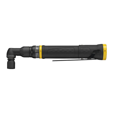
Sherex FLEX?5S Operating instructions

Repair Manual
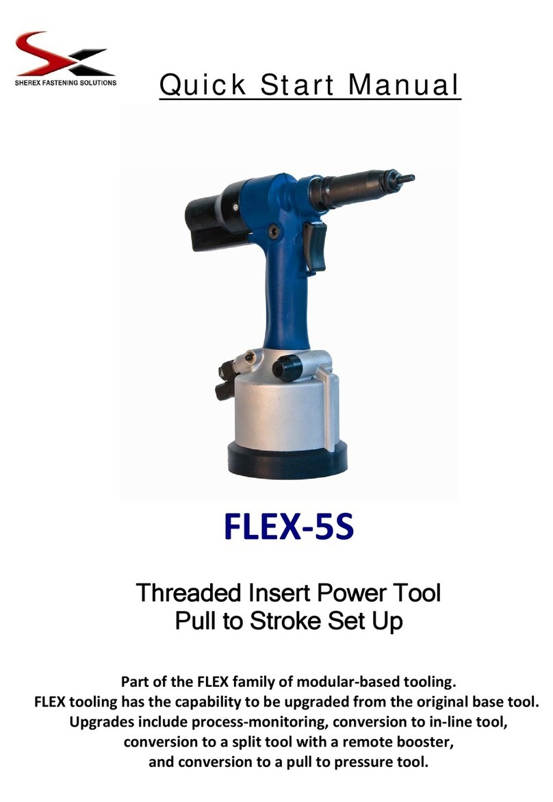
FLEX-5S
Threaded Insert Power Tool
Pull to Stroke Set Up
Part of the FLEX family of modular-based tooling.
FLEX tooling has the capability to be upgraded from the
original base tool. Upgrades include process-monitoring,
conversion to an in-line tool, conversion to a split tool with a
remote booster, and conversion to a pull to pressure tool.

cONTENTS
SAFETY.........................................................................................................................................................................2
TOOL OVERVIEW.........................................................................................................................................................3
TOOL SIZE CAPABILITIES...........................................................................................................................................4
TOOL SPECIFICATIONS..............................................................................................................................................5
AIR SERVICE................................................................................................................................................................6
HEAD SET ASSEMBLY................................................................................................................................................6
HEAD SET COMPONENTS..........................................................................................................................................7-8
STROKE ADJUSTMENT PROCEDURE......................................................................................................................9
OPERATION.................................................................................................................................................................9
MAINTENANCE...........................................................................................................................................................10
TOOL DISASSEMBLY...............................................................................................................................................11-19
TROUBLESHOOTING.................................................................................................................................................20
PROCESS MONITORING............................................................................................................................................21
SHEREX TOOL SHOWCASE......................................................................................................................................22
SHEREX PRODUCT LINE SHOWCASE.....................................................................................................................23
Sherex Warranty
Sherex Fastening Solutions FLEX-5S carries a 6 month warranty against defects that are
caused by faulty materials or workmanship. Sherex warranty period commences from the
date of delivery which is confirmed either by the invoice or delivery note. The warranty
becomes invalidated if the installation tool is misused or not serviced, maintained, and
operated according to the instructions in the Quick Start and Repair Manuals.

2
SAFETY
DO NOT USE THIS TOOL FOR ANY PURPOSE OTHER THAN THOSE SPECIFIED.
DO NOT USE ANY EQUIPMENT ALONG WITH THE TOOL THAT HAS NOT BEEN
RECOMMENDED OR PROVIDED BY SHEREX FASTENING SOLUTIONS.
▪Failure to do so could result in voided warranty and/or personal injury
THIS TOOL MUST BE KEPT IN EXCELLENT CONDITION AND SHOULD BE CHECKED
BY SPECIALIZED PERSONNEL ON A REGULAR BASIS TO DETECT DAMAGES AND
EVALUATE ITS OPERATING CONDITION.
ALWAYS DISCONNECT THE AIR SUPPLY BEFORE SET UP, ADJUSTMENT, OR
REMOVAL OF THE HEAD SET.
AIR INLET SHALL NOT EXCEED 7 BAR (102 PSI).
DO NOT USE THE TOOL WITHOUT OIL PLUG IN PLACE.

3
TOOL OVERVIEW
The FLEX-5S tool is designed for installing Sherex threaded insert/rivet nuts. The tool utilizes a pull to
stroke installation method. The advantage with this method is that the pulling distance of the tool can
be set to a specified distance ensuring the rivet nut insert is pulled to the same position (distance)
with each actuation of the tool. Contact Sherex for the conversion instructions for changing this tool to
a pull to pressure (FLEX-5P) installation method.
The tool is designed to install rivet nuts from M3 to M10 & #4-40 to 3/8-24. The recommended
operating air pressure is between 5 - 7 bar (72.5 - 101.5 PSI).

4
TOOL SIZE CAPABILITIES
SHEREX® Rivet Nut Series
Thread Sizes
& Materials
CAL
CAK CPB CA CFT TU CLM
CAH CPN CFH CFW CKM
CAO
#6 & M3
Aluminum Flex 5S ONLY X Flex 5S ONLY Flex 5S ONLY Flex 5S ONLY Flex 5S ONLY
Steel X
Stainless Steel X
#8 & M4
Aluminum Flex 5S ONLY X Flex 5S ONLY Flex 5S ONLY Flex 5S ONLY Flex 5S ONLY
Steel
X
Stainless Steel X
#10 & M5
Aluminum X
Steel X
Stainless Steel X
1/4 & M6
Aluminum X
Steel X
Stainless Steel X
5/16 & M8
Aluminum X X
Steel X X
Stainless Steel Consult Sherex X X X Consult Sherex
3/8 & M10
Aluminum X X X
Steel X X X
Stainless Steel Consult Sherex X X X Consult Sherex
FLEX-5 Tool Recommended
X FLEX-5 Tool Not Recommended
The FLEX-5P & FLEX-5S can install all RIV-FLOAT® &
RIV-FLOAT®-SHORT Rivet Nuts up to 5/16-24 (M8)
Reference Page 8 for RIV-FLOAT® & RIV-FLOAT®-SHORT Head Set Part Numbers

5
SPECIFICATIONS
FLEX-5S TOOL DIMENSIONS
FLEX-5S Tool Specifications
AIR PRESSURE Minimum - Maximum 5 – 7 bar 72-101 psi
STROKE Maximum 7 mm .280 in
MOTOR SPEED SPIN ON 1500 rpm
SPIN OFF 2000 rpm
PULL FORCE @ 6.2 bar 22.25 kN 5,000 lbf
CYCLE TIME Approximately 2.5 sec
NOISE LEVEL Less than 70 dB(A)
WEIGHT Without kit 1.9 kg 4.2 lbs
VIBRATION Less than 2.5 m/s2
PLACING FEATURES Inserts M3 – M10 #4-40 – 3/8-24
Contact Sherex should you require a pull to
stroke setup for this tool (FLEX 5P)
Dimensions shown in bold are in inches.
The other dimensions are in millimeters.
10.45
265.43
4.32
109.73
2.0
50.3
10.24
260.1

6
SERVICE
AIR SUPPLY
We suggest you use a pressure regulator and automatic oiling / filtering system on the main air
supply, to ensure its maximum life cycle with reliable trouble free use.
HEAD SET ASSEMBLY
ASSEMBLY INSTRUCTIONS
Choose the proper head set.
Remove the nose case, if still mounted.
Unscrew the adaptor nut while moving away the stop pins.
Insert hex driver 4into hex hole on spindle, place socket head cap screw (mandrel) 3on to
hex driver 4and reducing sleeve 5on mandrel 3.
Hold the adaptor nut, ensure the stop pins are seated in the last possible notch on the adapter
nut (may require you to turn forward 1 notch).
Screw on the nose case into the handle casting.
Screw on the anvil 1/2 onto the nose case.
To remove the equipment, do the reverse operation.
PLACING RIVET NUT ONTO MANDREL- LENGTH CHECK
Keeping the tool disconnected from air supply, place an insert on mandrel 3and adjust anvil 1
and lock nut 2 in order to match the insert and mandrel end. It is ideal to have 1-2 threads of
the mandrel protruding from the back of the rivet nut; this will ensure full thread engagement
during the installation process. Lock position by tightening lock nut 2 against the nose case.
Head sets should be serviced weekly. Any damaged or worn out parts should be replaced. Check
for mandrel wear and replace when necessary. Sherex recommends using high quality socket head
cap screws such as Unbrako® and Holo-Krome®.
IMPORTANT
DISCONNECT THE AIR SUPPLY WHEN SETTING UP OR REMOVING A HEAD SET.
Nose Case

7
HEAD SET COMPONENTS
Head sets vary in shape according to the insert thread size. Each head set represents a unique group
of components that can be ordered individually and are unique to the size of the fastener. We suggest
you keep the components listed below in stock to be used as replacements.
(Numbers refer to sketch on previous page).
THREAD SIZE COMPLETE
HEAD SET
1+2
ANVIL
3
MANDREL
4
HEX DRIVER
5
REDUCING SLEEVE
STANDARD RIVET NUTS
M3 FL5-HS-M3 FL5-HS-00903
M-M3-40 FL5-HS-01003 FL5-HS-09103
M4 FL5-HS-M4 FL5-HS-00904
M-M4-55 FL5-HS-01004 FL5-HS-09104
M5 FL5-HS-M5 FL5-HS-00905
M-M5-65 FL5-HS-01005 FL5-HS-09105
M6 FL5-HS-M6 FL5-HS-00906
M-M6-65 FL5-HS-01006 FL5-HS-09106
M8 FL5-HS-M8 FL5-HS-00908
M-M8-65 FL5-HS-01008 FL5-HS-09108
M10 FL5-HS-M10 FL5-HS-00910
M-M10-65 FL5-HS-01010 XXXX
# 4-40 UNC FL5-HS-0440 FL5-HS-00854 M-0440-175 FL5-HS-00754 FL5-HS-09154
# 6-32 UNC FL5-HS-0632 FL5-HS-00856
M-0632-175 FL5-HS-00756 FL5-HS-09156
# 8-32 UNC FL5-HS-0832 FL5-HS-00858
M-0832-175 FL5-HS-00758 FL5-HS-09158
# 10-24 UNC FL5-HS-1024 FL5-HS-00850
M-1024-250 FL5-HS-00750 FL5-HS-09150
# 10-32 UNF FL5-HS-1032 FL5-HS-00850
M-1032-250 FL5-HS-00750 FL5-HS-09150
1/4-20 UNC FL5-HS-2520 FL5-HS-00848
M-2520-250 FL5-HS-00748 FL5-HS-09148
1/4-28 UNF FL5-HS-2528 FL5-HS-00848
M-2528-250 FL5-HS-00748 FL5-HS-09148
5/16-18 UNC FL5-HS-3118 FL5-HS-00840
M-3118-250 FL5-HS-00740 FL5-HS-09140
5/16-24 UNF FL5-HS-3124 FL5-HS-00840
M-3124-250 FL5-HS-00740 FL5-HS-09140
3/8-16 UNC FL5-HS-3716 FL5-HS-00842
M-3716-250 FL5-HS-00742 XXXX
3/8-24 UNF FL5-HS-3724 FL5-HS-00842
M-3724-250 FL5-HS-00742 XXXX
RIVET NUT STUDS
M5 FL5-HS-M5S FL5-HS-S0905 FL5-HS-0S005 FL5-HS-01010 XXXX
M6 FL5-HS-M6S FL5-HS-S0906 FL5-HS-0S006 FL5-HS-01010 XXXX
M8* FL5-HS-M8S FL5-HS-S0908 FL5-HS-0S008 FL5-HS-01010 XXXX
# 10-24 UNC FL5-HS-1024S FL5-HS-S0850 FL5-HS-S1024 FL5-HS-01010 XXXX
# 10-32 UNF FL5-HS-1032S FL5-HS-S0850 FL5-HS-S1032 FL5-HS-01010 XXXX
¼-20 UNC FL5-HS-2520S FL5-HS-S0848 FL5-HS-S2520 FL5-HS-01010 XXXX
¼-28 UNF FL5-HS-2528S FL5-HS-S0848 FL5-HS-S2528 FL5-HS-01010 XXXX
5/16-18 UNC* FL5-HS-3118S FL5-HS-S0840 FL5-HS-S3118 FL5-HS-01010 XXXX
5/16-24 UNF* FL5-HS-3124S FL5-HS-S0840 FL5-HS-S3124 FL5-HS-01010 XXXX
*Headsets include p/n FL5-HS-12S92 adaptor nut
RIVET NUT STUD
HEAD SET ASSEMBLY
Nose Casing

8
HEAD SET COMPONENTS - RIV-FLOAT®
THREAD SIZE COMPLETE
HEAD SET
1+2
ANVIL
3
MANDREL
4
HEX DRIVER
5
REDUCING SLEEVE
RIV-FLOAT® Riv-float® is covered under U.S. Patent No. 7,713,011
M3 FL5-HS-2528R FL5-HS-00848 M-2528-225 FL5-HS-00748 FL5-HS-09148
M4 FL5-HS-2528R FL5-HS-00848 M-2528-225 FL5-HS-00748 FL5-HS-09148
M5 FL5-HS-M5R FL5-HS-R0995 M-M5-65 FL5-HS-01005 FL5-HS-09105
M6 FL5-HS-M6R FL5-HS-R0996 M-M6-65 FL5-HS-01006 FL5-HS-09106
# 4-40 UNC FL5-HS-2528R FL5-HS-00848 M-2528-225 FL5-HS-00748 FL5-HS-09148
# 6-32 UNC FL5-HS-2528R FL5-HS-00848 M-2528-225 FL5-HS-00748 FL5-HS-09148
# 8-32 UNC FL5-HS-2528R FL5-HS-00848 M-2528-225 FL5-HS-00748 FL5-HS-09148
# 10-24 UNC FL5-HS-1024R FL5-HS-R0950 M-1024-250 FL5-HS-00750 FL5-HS-09150
# 10-32 UNF FL5-HS-1032R FL5-HS-R0950
M-1032-250 FL5-HS-00750 FL5-HS-09150
1/4-20 UNC FL5-HS-2520R FL5-HS-R0948
M-2520-250 FL5-HS-00748 FL5-HS-09148
1/4-28 UNF FL5-HS-2528R1 FL5-HS-R0948 M-2528-250 FL5-HS-00748 FL5-HS-09148
RIV-FLOAT®-SHORT Patent Pending
M4 FL5-HS-M4SR FL5-HS-SR0994 M-M4-55 FL5-HS-01004 FL5-HS-09104
M5 FL5-HS-M5SR FL5-HS-SR0995 M-M5-65 FL5-HS-01005 FL5-HS-09105
# 8-32 UNC FL5-HS-0832SR FL5-HS-SR0858 M-0832-150 FL5-HS-00758 FL5-HS-09158
# 10-24 UNC FL5-HS-1024SR FL5-HS-SR0950 M-1024-225 FL5-HS-00750 FL5-HS-09150
# 10-32 UNF FL5-HS-1032SR FL5-HS-SR0950 M-1032-225 FL5-HS-00750 FL5-HS-09150
(
Numbers refer to sketch on previous pa
g
e 6
)

9
STROKE ADJUSTMENT PROCEDURE
Determine the proper stroke distance of the tool based on the size
and style of rivet nut insert you are using for your application material
thickness. Contact Sherex should you require assistance determining
the appropriate stroke. Warning** A stroke setting that is too large for
the application may cause an over installed installation condition
which may damage the mandrel, the base material, and/or the rivet
nut insert.
Install the proper head set for the rivet nut thread size that
you will be using. Attach an air supply to the Air Inlet (1)
per the recommendations in this manual.
To adjust the stroke distance of the tool, use the key
provided with the tool and place it in the stroke adjustment
ring (3) located in the cut out of the back cover. The ring, when
threaded fully in, will pull to 1 mm (0.040”) of stroke. Turning the key counter-clockwise from one side
of the window to the other will increase the stroke approximately .12 mm (.005). Continue to adjust
the ring out until you have approximated the stroke distance required. Test by installing a rivet nut and
measuring the collapsed distance of the part. Adjust the ring as required to achieve the desired
installation distance. Note**Threading the adjustment ring beyond the 6 mm stroke may cause the
auto-reverse to not function. If this occurs, turn the adjustment ring in the opposite direction reducing
the stroke distance to 6 mm.
Thread an insert/rivet nut on to the mandrel (2) 1 or 2 turns. Apply pressure to the insert and the auto-
spin on feature will engage thereby spinning the rivet nut up the mandrel (2) until it comes in contact
with the anvil.
If during the set up process the tool does not automatically reverse out of the rivet nut press the
manual reverse button (4).
operation
Operating procedure
Head Set assembled, tool connected to air supply, stroke adjustment complete.
Screw the rivet nut onto the mandrel (2) a couple turns, then a light pressure on it will start the
spinning of the mandrel (push to spin) and automatically stop when the rivet nut comes in
contact with the anvil.
Insert fastener into the application.
Depress the trigger fully. This will place the insert and automatically reverse the tool out of the
installed rivet nut. (Depress the trigger and hold until auto-reverse engages). If auto-reverse
does not engage and insert has not collapsed, apply a manual pushing force to engage the
auto spin-on, and then depress the trigger. (Ensure the air pressure is within the specified
range).
If, at any time, manual-reverse (4) needs to be engaged, depress the button at the base of the
handle, to the right of the air inlet.
IMPORTANT
Do not push the mandrel without a rivet nut as this will cause the
mandrel to s
p
in automaticall
y
. Ensure
p
ressure settin
g
s are correct.
Stroke Adjustment
Rin
g
(
3
)
Air Inlet (1)
Socket Head Cap
Screw Mandrel (2)
Manual Reverse
Button (4)

10
MAINTENANCE
Servicing should be performed on a regular basis and a complete inspection will be needed once a
year or every 500,000 cycles, whichever comes first.
DAILY SERVICING
Every day, before use, pour a few drops of light lubricating oil on tool air inlet,
if the air supply is not equipped with lubricator.
Check for air leaks. If damaged, hoses and coupling should be replaced.
Make sure you are using the proper head set.
Make sure the pull stroke is correct for the selected rivet nut.
Check the mandrel for wear or damage and replace if needed.
WEEKLY SERVICING
Check for oil and air leaks.
MAINTENANCE
Every 500,000 cycles the tool should be completely checked and parts that are worn or damaged
should be replaced. O rings should be replaced and lubricated with Molykote®55M grease before
assembly.
Only a trained technician should service the Flex 5S tool. Should the Flex 5S tool require repair, the
tool can be sent to the Sherex authorized repair center:
Alcorn Industrial, Inc
5412 Rock Hampton Court
Indianapolis, IN 46268
sales@alcornindustrial.com
1-800-317-4775
P R I M I NG P R O C E D U R E
• Place the tool on its side with the oil plug facing up.
• With a 5mm Allen key, unscrew the oil plug
• Fill tool with DEA Astron HLP 32 hydraulic fluid, or equivalent
•Gently rock tool back and forth to express any trapped air
•Return oil plug and tighten
•Connect air supply and cycle the tool multiple times
•Disconnect air supply and unscrew oil plug a few turns
•Re-tighten oil plug
•If, at any time, oil is leaking from the reservoir, replace the o-ring
located at the top of the threaded section.
IMPORTANT
The employer is the sole responsible party for ensuring the training of staff on proper
tool use and maintenance. The operator should not perform any servicing or repairs,
unless properly trained.

11
TOOL DISASSEMBLY

12
FLEX-5S SPARE PARTS
Ref. Sherex
Part Number Description Ref.
Sherex
Part Number Description
1 FLEX5-12091 NOSE CASE 44 FLEX5-K4044 O RING KIT 4 pcs
2 FLEX5-12092 ADAPTOR NUT 45 FLEX5-K0045 TRIGGER KIT WITH OR
3 FLEX5-12093 JOINT KIT 46 FLEX5-00046 TRIGGER
4 FLEX5-12044 SPINDLE 47 FLEX5-00047 PIN
5 FLEX5-00803 NUT 48 FLEX5-03013 AIR CYLINDER
6 FLEX5-12056 PISTON ROD 49 FLEX5-12024 AIR MOTOR BODY
7 FLEX5-02004 SEAL 50 FLEX5-00050 O RING
8 FLEX5-12053 SEAL 51 FLEX5-00051 RING NUT
9 FLEX5-12121 O RING 52 FLEX5-00052 SPINDLE
10 FLEX5-12014 OIL PISTON 53 FLEX5-00053 COVER
11 FLEX5-12015 SPRING 54 FLEX5-00054 O RING
12 FLEX5-S0012 RING NUT 55 FLEX5-00055 RING NUT
13 FLEX5-03014 SCREW 56 FLEX5-00056 COVER
14 FLEX5-S0014 MOTOR COVER 57 FLEX5-00057 SPINDLE
15 FLEX5-12078 PUSHING ROD 58 FLEX5-00058 O RING
16 FLEX5-00026 O RING 59 FLEX5-00059 O RING
17 FLEX5-12079 BALL 60 FLEX5-00060 O RING
18 FLEX5-12027 DISTRIBUTOR 61 FLEX5-00061 SEAL
19 FLEX5-12007 SCREW 62 FLEX5-00062 SHIM
20 FLEX5-03022 O RING 63 FLEX5-00063 ROD GUIDE
21 FLEX5-12060 O RING 64 FLEX5-00064 SEAL
22 FLEX5-03009 AIR TUBE 65 FLEX5-00065 O RING
23 FLEX5-01274 OIL PLUG 66 FLEX5-00066 O RING
24 FLEX5-03015 OIL SEAL 67 FLEX5-00067 O RING
25 FLEX5-12037 HANDLE 68 FLEX5-00068 O RING
26 FLEX5-K8026 SCREW OFF KIT 8 pcs 69 FLEX5-00069 O RING
27 FLEX5-K5027 O RING KIT 5 pcs 70 FLEX5-00070 SPRING
28 FLEX5-K5028 ROD GUIDE KIT 5 pcs 71 FLEX5-00071 REGULATOR
29 FLEX5-K3029 SEAL KIT 3 pcs 72 FLEX5-00072 RUBBER CUP
30 FLEX5-K0030 SWIVEL AIR KIT 73 FLEX5-00073 RING NUT
31 FLEX5-00205 SPRING 74 FLEX5-00074 SPACER
32 FLEX5-03018 ROD 75 FLEX5-00075 SLIDER
33 FLEX5-12008 SEAL 76 FLEX5-00076 COVER
34 FLEX5-03020 PISTON 77 FLEX5-00077 SPINDLE
35 FLEX5-12002 RUBBER BASE 78 FLEX5-00078 SEAL
36 FLEX5-12036 ELASTIC RING 79 FLEX5-00079 SPINDLE
37 FLEX5-03023 O RING 80 FLEX5-00080 SPRING
38 FLEX5-00038 PLATE 81 FLEX5-00081 BOTTOM
39 FLEX5-00039 PIN 82 FLEX5-00082 O RING
40 FLEX5-K4040 O RING KIT 4 pcs 83 FLEX5-00083 O RING
41 FLEX5-K1741 PRESSURE KIT 17 pcs 84 FLEX5-00084 O RING
42 FLEX5-K7042 SEALS KIT + OR 7 Pcs 85 FLEX5-00085 O RING
43 FLEX5-K2043 SPRINGS KIT 2 pcs

13
FLEX-5S AIR MOTOR SPARE PARTS
Ref Sherex
Part Number Description
1A FLEX5-12063 PLANET GEAR SPINDLE
2A FLEX5-09208 PLANET
3A FLEX5-12066 SPACER
4A FLEX5-09210 FRONT WASHER
5A FLEX5-09211 STATOR
6A FLEX5-09213 WING
7A FLEX5-09216 PLUG
8A FLEX5-12061 SEEGER
9A FLEX5-12062 BEARING
10A FLEX5-12065 CROWN
11A FLEX5-09206 BEARING
12A FLEX5-12070 ROTOR
13A FLEX5-09214 BACK WASHER
14A FLEX5-09215 BEARING
AIR MOTOR

14
1: Place the tool on its side, with
the oil plug side up
2: With a 5mm Allen key,
Unscrew the oil plug 23.
3: Drain the oil in a proper
container
Safety Instructions appear on pages 2.
The operator should not be involved in maintenance or repair of the tool unless
properly trained.
The air line must be disconnected before any servicing or dismantling.
It is recommended that any dismantling operation be carried out in clean conditions.
Item numbers in bold refer to the general assembly and parts list on pages 9and 10.
Before dismantling the tool, you should remove the nose assembly. Please refer to the nose
assemblies section on page 4for instructions.
For a complete tool servicing, we suggest you dismantle the sub-assemblies
as shown on pages 11-16.
Prime after assembly to restore the full stroke.
OIL DRAINAGE

15
1 PNEUMATIC CYLINDER
1: Remove rubber base cover 35
2: Remove the snap ring 36
3: Remove the plate 38 and O Ring 37
4: Remove pneumatic piston
assembly.
This should release itself under the
pressure of spring (however it
maybe necessary to push the
piston against the spring to
activate the release)
5: Remove spring 31 and inspect
for damaged rod, 32, piston, 34,
and seal 33.

16
2 ROD GUIDE
Ensure oil is drained
1: Unscrew rod guide
2: Unscrew the nut
3: Remove the seals
(28 Complete kit - 5 pcs.)
(
29 Seal kit - 3
p
cs.
)
3 TRIGGER
44 O Ring kit 4 - pcs.
45 Trigger Kit with O Ring
3: Remove nut
4: Remove O ring
5: Remove the pin with pliers
1: Remove pin 47
2: Remove tri
gg
er 46

17
5 MANUAL REVERSE
4 PRESSURE REGULATOR
1: Remove rubber cover
2: Remove end cap
Internal Parts
41 Complete kit 17 - pcs. 42 Seals kit 7 - pcs. 43 Springs kit 2 - pcs.
Seat 26 Complete kit valve and O Ring 8 - pcs. 27 O Ring kit 5 - pcs.

18
6 SWIVEL AIR INLET
7 AIR MOTOR 8 HYDRAULIC PISTON
30 Complete kit swivel air inlet
Remove Screws 13 Motor Cover 14 Screws 19 Air Tubes 22 O Ring 21
Screw off the ring nut 12 Spring 11
Piston rod 6Seal 8O Ring 9Seal 7Piston 10
S
p
rin
g
3Nut 5S
p
indle 4

19
49
9A
10
2A
1A
10A
3A
11A
4A
5A
6
6A
5A
11A
4A
7.1 AIR MOTOR ASSEMBLY
1 Components 11A to 7A can be
pulled out all together, making sure
not to drop pin 7A.
2 Using a soft mallet, tap splined head
of rotor 12A.
3 Bearing 11A and the front washer
4A will come out with stator 5A and
five rotor blades 6A (rotor 12A
remains in your hands)
4 Place rear end plate 13A in vice
with soft jaws.
5 Using a pin punch, tap rotor 12A’s
center to remove bearing 14A (turn
rotor 12A upside down and the
bearing 14A will come out).
12A 13A 14A
Other manuals for FLEX?5S
1
Table of contents
Other Sherex Power Tools manuals
