Sherex FLEX-18 Instruction manual

Threaded
Insert
Power
Tool
Quick Start Manual
PartoftheFLEXfamilyofmodular‐basedtooling.
FLEXtoolinghasthecapabilitytobeupgradedfromtheoriginalbasetool.
Upgradesincludeprocess‐monitoring.
FLEX‐18
SHEREX® ~ 400 Riverwalk Pkwy, Suite 600 Tonawanda, NY, 14150 ~ 866-4SHEREX ~ www.sherex.com
cONTENTS
SAFETY.........................................................................................................................................................................2
TOOL OVERVIEW.........................................................................................................................................................3
TOOL SPECIFICATIONS..............................................................................................................................................4
AIR SERVICE................................................................................................................................................................5
STANDARD HEAD SET ASSEMBLY..........................................................................................................................5
LARGE THREAD HEAD SET ASSEMBLY..................................................................................................................6
HEAD SET COMPONENTS.........................................................................................................................................7
TOOL SETUP............................................................................................ ..................................................... ............8
GENERAL SETTING....................................................................................................................................................8
FORCE ADJUSTMENT................................................................................................................................................9
STROKE ADJUSTMENT..............................................................................................................................................10
OPERATION.................................................................................................................................................................11
MAINTENANCE...........................................................................................................................................................12
TROUBLESHOOTING.................................................................................................................................................13
SHEREX PRODUCT LINE SHOWCASE.....................................................................................................................14
Sherex Warranty
Sherex Fastening Solutions FLEX-18 carries a 6 month warranty against defects that are
caused by faulty materials or workmanship. Sherex warranty period commences from the
date of delivery which is confirmed either by the invoice or delivery note. The warranty
becomes invalidated if the installation tool is misused or not serviced, maintained, and
operated according to the instructions in the Quick Start and Repair Manuals.

SHEREX® ~ 400 Riverwalk Pkwy, Suite 600 Tonawanda, NY, 14150 ~ 866-4SHEREX ~ www.sherex.com
2
SAFETY
DO NOT USE THIS TOOL FOR ANY PURPOSE OTHER THAN THOSE SPECIFIED.
DO NOT USE ANY EQUIPMENT ALONG WITH THE TOOL THAT HAS NOT BEEN
RECOMMENDED OR PROVIDED BY SHEREX FASTENING SOLUTIONS.
▪Failure to do so could result in voided warranty and/or personal injury
THIS TOOL MUST BE KEPT IN EXCELLENT CONDITION AND SHOULD BE CHECKED
BY SPECIALIZED PERSONNEL ON A REGULAR BASIS TO DETECT DAMAGES AND
EVALUATE ITS OPERATING CONDITION.
ALWAYS DISCONNECT THE AIR SUPPLY BEFORE SET UP, ADJUSTMENT, OR
REMOVAL OF THE NOSE ASSEMBLY.
AIR INLET SHALL NOT EXCEED 7 BAR (102 PSI).
DO NOT USE THE TOOL WITHOUT OIL PLUG IN PLACE.
SHEREX® ~ 400 Riverwalk Pkwy, Suite 600 Tonawanda, NY, 14150 ~ 866-4SHEREX ~ www.sherex.com
3
TOOL OVERVIEW
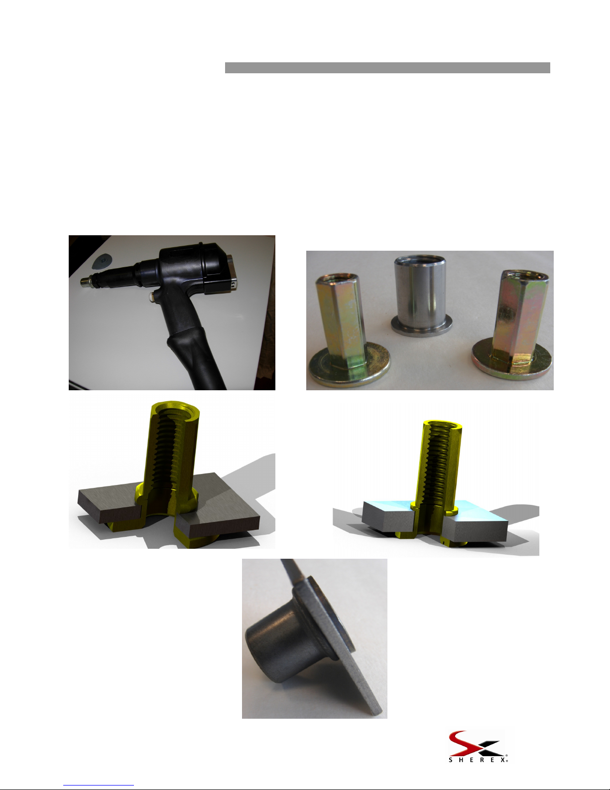
The FLEX-18 tool is designed for installing Sherex threaded insert/rivet nuts. The tool has the ability
to utilize a pull to pressure or pull to stroke installation method depending on the application. The
advantage with the pull to pressure method is that the same insert can be installed into different
material thicknesses (within the part grip range) without any adjustments to the tool once the proper
pulling pressure (force) has been set. The pull to stroke (distance) method allows the insert to be
installed to the same distance each time. This is helpful when installing into soft materials (prevents
crushing of the base material) or when a specific installed length is required.
The tool is designed to install rivet nuts from M8 to M20 & 5/16-18 to 3/4-16. The recommended
operating air pressure is between 5 - 7 bar (72.5 - 101.5 PSI).
SHEREX® ~ 400 Riverwalk Pkwy, Suite 600 Tonawanda, NY, 14150 ~ 866-4SHEREX ~ www.sherex.com
4
SPECIFICATIONS
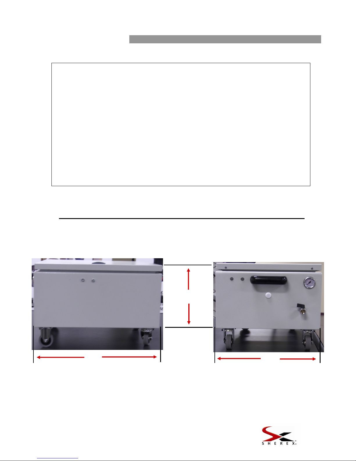
FLEX-18 BOOSTER BOX DIMENSIONS
FLEX-18 Tool Specifications
AIR PRESSURE Minimum - Maximum 5 – 7 bar 72-101 psi
STROKE Maximum 15 mm .591 in
MOTOR SPEED SPIN ON 2000 rpm
SPIN OFF 2000 rpm
PULL FORCE @ 6.2 bar 80 kN 18,000 lbf
CYCLE TIME Approximately 2.5 sec
NOISE LEVEL Less than 75 dB(A)
WEIGHT Without kit 2.3 kg 5.1 lbs
VIBRATION Less than 2.5 m/s2
THREAD SIZE Inserts M8 – M20 5/16-18 – ¾-16
Dimensions shown in bold are in inches.
The other dimensions are in centimeters.
15.75
40.0
Standard Hose Length - 15 Feet (457.2 cm)
Extended Hose Length - 22 Feet (670.56 cm)
19.75
50.2
13.50
34.3
SHEREX® ~ 400 Riverwalk Pkwy, Suite 600 Tonawanda, NY, 14150 ~ 866-4SHEREX ~ www.sherex.com
5
SERVICE
AIR SUPPLY
We suggest you use a pressure regulator and automatic oiling / filtering system on the main air
supply, to ensure its maximum life cycle with reliable trouble free use.
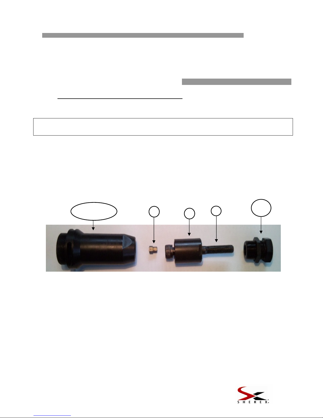
STANDARD HEAD SET ASSEMBLY
ASSEMBLY INSTRUCTIONS
Choose the proper head set according to the insert that will be installed.
Remove the standard nose case, if still mounted.
Insert Hex Driver 4 into hex hole on spindle; place the mandrel 3 on to hex driver 4and
adaptor nut 5on mandrel 3.
Screw on Adaptor Nut 5completely and tighten.
Screw on the standard nose case into the handle casting and tighten.
Screw on the anvil 1and lock nut 2 onto the standard nose case.
To remove the equipment, do the reverse operation
PLACING RIVET NUT ONTO MANDREL- LENGTH CHECK
Keeping the tool disconnected from air supply, place an insert on mandrel 3 and adjust anvil 1
and lock nut 2 in order to match the insert and mandrel end. It is ideal to have 1-2 threads of
the mandrel protruding from the back of the rivet nut; this will ensure full thread engagement
during the installation process. Lock position by tightening lock nut 2 against the standard
nose case.
Head Sets should be serviced weekly. Any damaged or worn out parts should be replaced. Check
for mandrel wear and replace when necessary. Sherex recommends using high quality socket head
cap screws such as Unbrako® and Holo-Krome®.
IMPORTANT
DISCONNECT THE AIR SUPPLY WHEN SETTING UP OR REMOVING A HEAD SET.
For Thread Sizes M8-M14 & 5/16-18 to 1/2-20
1+2
3
5
4
Standard
Nose Case

SHEREX® ~ 400 Riverwalk Pkwy, Suite 600 Tonawanda, NY, 14150 ~ 866-4SHEREX ~ www.sherex.com
6
LARGE THREAD HEAD SET ASSEMBLY
ASSEMBLY INSTRUCTIONS
Choose the proper head set according to the insert that will be installed.
Remove the large thread nose case, if still mounted.
Thread the mandrel 3 on the spindle and tighten.
Screw on the large thread nose case into the handle casting and be sure to fully tighten.
Screw on the anvil 1onto the large thread nose case.
To remove the equipment, do the reverse operation
PLACING RIVET NUT ONTO MANDREL- LENGTH CHECK
Keeping the tool disconnected from air supply, place an insert on mandrel 3 adjust anvil 1in
order to match the insert and mandrel end. It is ideal to have 1-2 threads of the mandrel
protruding from the back of the rivet nut; this will ensure full thread engagement during the
installation process.
Nose assemblies should be serviced weekly. Any damaged or worn out parts should be replaced.
Check for mandrel wear and replace when necessary. Sherex recommends using high quality socket
head cap screws such as Unbrako® and Holo-Krome®.
IMPORTANT
DISCONNECT THE AIR SUPPLY WHEN SETTING UP OR REMOVING A HEAD SET.
For Thread Sizes M16-M20 & 5/8-11 to 3/4-16
1
Large Thread
Nose Case
3

SHEREX® ~ 400 Riverwalk Pkwy, Suite 600 Tonawanda, NY, 14150 ~ 866-4SHEREX ~ www.sherex.com
7
HEAD SET COMPONENTS
Head Sets vary in shape according to the insert thread size. Each head set represents a unique group
of components that can be ordered individually and are unique to the size of the fastener. We suggest
you keep the components listed below in stock to be used as replacements.
(Numbers refer to sketches on pages 5 & 6).
FLEX-18 TOOL HEAD SET COMPONENTS
STANDARD NOSE CASE
THREAD SIZE COMPLETE HEAD SET 1+2
ANVIL
3
MANDREL
4
HEX DRIVER
5
ADAPTOR NUT
M8 FL18-HS-M8 FL18-HS-00908 M-M8-65 FL5-HS-01008 FL18-HS-09108
M10 FL18-HS-M10 FL18-HS-00910 M-M10-65 FL5-HS-01010 FL18-HS-09110
M12 FL18-HS-M12 FL18-HS-00912 M-M12-65 FL18-HS-01012 FL18-HS-09112
5/16-18 UNC FL18-HS-3118 FL18-HS-00908 M-3118-250 FL5-HS-00740 FL18-HS-09108
5/16-24 UNF FL18-HS-3124 FL18-HS-00908 M-3124-250 FL5-HS-00740 FL18-HS-09108
3/8-16 UNC FL-18-HS-3716 FL18-HS-00910 M-3716-300 FL5-HS-00742 FL18-HS-09110
3/8-24 UNF FL18-HS-3724 FL18-HS-00910 M-3724-300 FL5-HS-00742 FL18-HS-09110
1/2-13 UNC FL18-HS-5013 FL18-HS-00950 M-5013-300 FL18-HS-00750 FL18-HS-09150
1/2-20 UNF FL18-HS-5020 FL18-HS-00950 M-5020-300 FL18-HS-00750 FL18-HS-09150
BIG NOSE CASE
THREAD SIZE COMPLETE HEAD SET 1
ANVIL
3
MANDREL
M16 FL18-HS-M16 FL18-HS-00916 M-M16-FL18
5/8-11 FL18-HS-6211 FL18-HS-00962 M-6211-FL18
¾-10 UNC FL18-HS-7510 FL18-HS-00975 M-7510-FL18
Contact Sherex for FLEX-18 Repair Part Numbers

SHEREX® ~ 400 Riverwalk Pkwy, Suite 600 Tonawanda, NY, 14150 ~ 866-4SHEREX ~ www.sherex.com
8
TOOL SETUP
Once the tool has been set up with the proper head set for the rivet nut thread size, it is now
time to set up the tool for installing blind rivet nuts. At this point you must determine the proper
installation method for installing the rivet nuts. Feel free to call Sherex to discuss your application and
proper installation method, but included below is a brief outline of considerations for tool set up.
This tool utilizes both pull to force and pull to distance installation methods and these two
methods can be used simultaneously as well. The two methods are described in detail in the
following section of the manual but here is a brief summary:
Pull to Force (Pressure): The tool is set to a specified pull force and the tool will pull to this
force when the trigger is actuated. Once the tool reaches the specified pull force, the tool will engage
the auto-reverse function and thread out of the rivet nut.
Pull to Distance (Stroke): The stop block is set on the tool so that it pulls to a specific distance
(At MAX Force). Once the tool pulls to the specified distance the tool will engage the auto-reverse
and thread out of the rivet nut.
Sherex recommends the Pull to Force installation method for applications involving steel,
aluminum, stainless base materials. The tool will compensate for any variation in material thickness
and ensure the part is pulled to the proper force. In this case, typically the pull to distance stop block
is positioned at the MAX distance of the tool. However, in some applications you may want to
position the stop block so that the tool will pull the lesser of Pull to Force set up, or the stop block
distance setting. An example of this is if you are installing steel and aluminum rivet nuts and you want
to be sure that the Pull Force setting for the steel rivet nuts does not strip the threads of the aluminum
rivet nuts. By setting to the tool up this way, you are able to install both rivet nuts without adjustment.
Sherex recommends Pull to Distance installation method for applications going into soft
materials like composites. In this situation the Pull to Distance method ensures that the base material
is not crushed during the installation process.
Choosing between these two installation methods (or a combination) is critical for proper rivet
nut installation. Please contact Sherex for support.
GENERAL SETTING
Air Pressure Gage
for Box
Hydro-Pneumatic
Booster
Pneumatic Switches
Hydraulic Fluid Reserve
Air Pressure
Regulator into Box
Force Adjustment
Air Inlet (1)

SHEREX® ~ 400 Riverwalk Pkwy, Suite 600 Tonawanda, NY, 14150 ~ 866-4SHEREX ~ www.sherex.com
9
FORCE ADJUSTMENT
Install the proper nose assembly for the rivet nut thread size that you
will be using. Attach an air supply to the Air Inlet (1) per the
recommendations in this manual.
Using a 3 mm allen key, unscrew the force adjustment screw (3) out
until it stops. When pulling the trigger the tool should not pull back as
this is at minimum force.
Thread an insert/rivet nut on to the mandrel 1 or 2 turns. Apply
pressure to the insert and the auto-spin on feature will engage thereby
spinning the rivet nut up the mandrel until it comes in contact with the
anvil.
Take the force adjustment tool (2) that is provided, and place it into the
force adjustment screw (3). Attempt to set the rivet nut insert by
depressing the trigger fully and holding it until the tool has reversed out.
To adjust the force, turn the force adjustment tool (2) a ½ turn in
(clockwise) to increase the force or ½ turn out (counter clockwise) to
decrease the force. Continue turning the tool a ½ turn after each setting
attempt until there is deformation of the rivet nut. Continue to adjust the
force until the rivet nut fully installs. For second grip parts and larger,
you may need to test in material thickness to achieve a proper
installation.
Test the tool set up by installing rivet nuts in to the representative
material thickness to be used in the application and increase the force if
needed.
If you will be installing rivet nuts into different material thicknesses, test
the rivet nut in the thickest material location. This position will require
the most installation force.
If during the set up process the tool does not automatically reverse out
of the rivet nut press the manual reverse button (4).
Should the mandrel bind in the application (manual reverse button will
not work), use the included tool (5) to reverse the mandrel from the
insert.
Manual Reverse Button
(4)
Numbers refer to the images on pages 8 through 10
Force Adjustment Tool (2)
Force Adjustment Screw (3)

SHEREX® ~ 400 Riverwalk Pkwy, Suite 600 Tonawanda, NY, 14150 ~ 866-4SHEREX ~ www.sherex.com
10
STROKE ADJUSTMENT
Install the proper nose assembly for the rivet nut thread size that you
will be using. Attach an air supply to the Air Inlet (1) per the
recommendations in this manual.
Determine the proper stroke distance of the tool based on the size and
style of rivet nut insert you are using for your application material
thickness. Contact Sherex should you require assistance determining
the appropriate stroke. Warning** A stroke setting that is too large for
the application may cause an over installed installation condition which
may damage the mandrel, the base material, and/or the rivet nut insert.
Adjustment of the pull distance (stroke) is accomplished by using the
provided stroke adjustment tool (5) to adjust the stop ring at the back of
the tool. The stop ring is threaded into the back of tool casing and is a
positive stop for the air motor. By turning the stop ring closer to the
casing (Clockwise) you reduce the pull distance (stroke) of the tool. By
turning the stop ring away from the casing (Counter clockwise) you
increase the pulling distance (stroke) of the tool.
If during the set up process the tool does not automatically reverse out
of the rivet nut press the manual reverse button (4).
Should the mandrel bind in the application (manual reverse button will
not work), use the included tool (5) to reverse the mandrel from the
insert.
Stroke Adjustment Tool (5)
Numbers refer to the images on pages 8 through 10
Manual Reverse Button
(4)

SHEREX® ~ 400 Riverwalk Pkwy, Suite 600 Tonawanda, NY, 14150 ~ 866-4SHEREX ~ www.sherex.com
11
OPERATION
Operating Procedure
Head Set assembled, tool connected to air supply, force/pull distance adjustment complete.
We recommend you set the pull distance (stroke) at the maximum distance you would want
the rivet nut installed, and then adjust the force to the size of the rivet nut. This will provide the
correct installation and prevent over installation of the rivet nut (and the potential damage this
can cause).
Screw the rivet nut onto the mandrel (2) a quarter turn, then apply a light pressure on the rivet
nut which will start the spinning of the mandrel (push to spin). The mandrel will automatically
stop when the rivet nut comes in contact with the nose piece.
Insert fastener into the application.
Depress the trigger fully and hold until tool has reversed out of the rivet nut. This tool has a
timer based auto reverse system so releasing the trigger prior to reverse will stop the reverse
process. If this occurs, press the red button on the top of the booster box for manual reverse.
IMPORTANT
Do not push the mandrel without a rivet nut as this will cause the
mandrel to spin automatically. Ensure pressure settings are correct.

SHEREX® ~ 400 Riverwalk Pkwy, Suite 600 Tonawanda, NY, 14150 ~ 866-4SHEREX ~ www.sherex.com
12
MAINTENANCE
Servicing should be performed on a regular basis and a complete inspection will be needed once a
year or every 500,000 cycles, whichever comes first.
DAILY SERVICING
Every day, before use, pour a few drops of light lubricating oil on tool air inlet,
if the air supply is not equipped with lubricator.
Check for air leaks. If damaged, hoses and coupling should be replaced.
Make sure you are using the proper nose assembly.
Make sure the pull force is correct for the selected rivet nut.
Check the mandrel for wear or damage and replace if needed.
WEEKLY SERVICING
Check for oil and air leaks.
Check oil level in reservoir (add as needed)
MAINTENANCE
Every 500,000 cycles the tool should be completely checked and parts that are worn or damaged
should be replaced. O rings should be replaced and lubricated with Molykote®55M grease before
assembly.
Only a trained technician should service the Flex-18 tool. Should the Flex-18 tool require repair
please contact Sherex.
IMPORTANT
The employer is the sole responsible party for ensuring the training of staff on proper
tool use and maintenance. The operator should not perform any servicing or repairs,
unless properly trained.

SHEREX® ~ 400 Riverwalk Pkwy, Suite 600 Tonawanda, NY, 14150 ~ 866-4SHEREX ~ www.sherex.com
13
TROUBLESHOOTING
SYMPTOM POSSIBLE CAUSE SOLUTION
Pneumatic motor
runs slowly
Motor air leaks
Check for worn out seals. Replace
Low air pressure
Increase it
Air vanes jammed
Lubricate tool through air inlet
Insert does not
deform properly
Pull force/Pull Stroke not set
properly
Adjust
Air pressure outside limits
Adjust
Low oil level
Add oil
Insert out of the grip
Check the insert grip range
Mandrel does not
spin
Mandrel worn/damaged
Replace Mandrel
Hex Driver worn/damaged
Replace Hex Driver
Loose locking ring
Tighten Locking Ring
Insert does not
spin on the
mandrel
Incorrect insert thread
Replace with proper insert
Incorrect mandrel
Replace with proper mandrel
Mandrel out or damaged
Replace
Tool is locked in
installed insert
Excessive pull force or distance
Depress manual spin off
If this does not work, disconnect air,
insert a pin through nose casing slots
and unscrew.
Reduce pull force or distance
Contact Sherex
Replace Mandrel
Defective insert
Defective or worn out or
damaged mandrel
Mandrel breaks
prematurely
Excessive pull force or distance
Reduce pull force or distance
Side load on mandrel
Keep the tool square to the application
when placing insert
Tool does not spin
on insert
No air supply
Insufficient distance between
locknut and spindle
Connect
Set distance between 1.5 and 2 mm??
Air motor jammed
Lubricate through air inlet or if required
contact Sherex authorized repair center
Auto reverse stops
working but the
manual reverse
does work
Oil level
Check oil level and if low add more oil to
the tool
SHEREX® ~ 400 Riverwalk Pkwy, Suite 600 Tonawanda, NY, 14150 ~ 866-4SHEREX ~ www.sherex.com
14
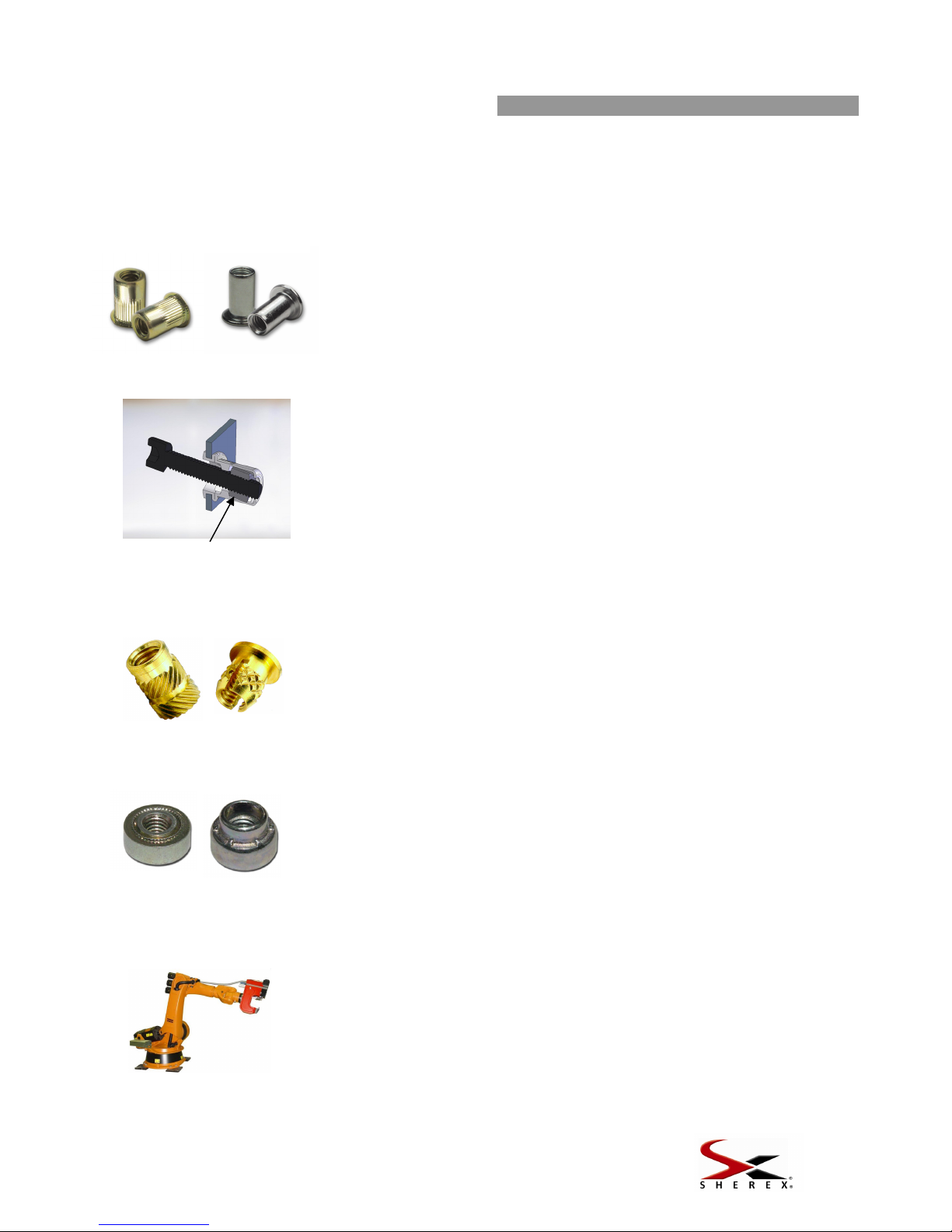
Sherex Product Line Showcase
The FLEX line of tooling is just one of many Product lines that
Sherex offers to help meet your application requirements
BLIND RIVET NUT
S
CLINCH NUTS
FASTENER
AUTOMATION
BRASS INSERTS
Brass inserts from Sherex Fastening Solutions are designed to provide a
threaded hole in plastics that are not strong enough to support a thread.
Brass inserts are available in many options such as ultrasonic, press-in,
flanged and molded-in. These inserts have a self aligning lead for accurate
installation and can be easily mounted. Suitable industry applications
include: automotive, communication and computer equipment, or almost
anywhere strong, durable threads are required in plastics.
Blind rivet nuts are suitable for providing load-bearing threads in thin
materials & blind applications. Sherex Fastening Solutions offers the
most comprehensive line of blind rivet nuts from thin wall parts to heavy
duty. Rivet Nuts are available in both an Inch Body Style & Metric Body
Style. Special designs are available to meet customer specific needs.
Sherex combines world class fastener manufacturing and design
capability with industry leading automation equipment to offer the best
solution for your application. This “One Source” service ensures that
you are receiving the best support before and after the start of
production. Whether you are using 10,000 pieces or 10 million pieces,
Sherex offers different levels of automation and fastener capability to
meet both your budget and performance requirements.
Sherex offers three different kinds of clinch nuts to meet the specific
requirements of the customer’s application. Sherex clinch nuts can be
used in various high strength steels such as dual phase alloy, HSLA, and
TRIPS to meet class 10 nut strength requirements. Sherex clinch nuts can
be used in any material that offers access from both sides of the base
material.
RIV
-
FLOA
T
®
Internally Floating Threads
RIV-FLOAT® is the next generation of fastening technology. Internally
floating threads allow for component attachment in off-center applications.
RIV-FLOAT® was designed for post finish installation in applications where
cage nuts, clinch nuts, floating nut plates or weld nuts are typically used. By
aligning to the drive angle of the screw, RIV-FLOAT® accounts for tolerance
stack up, saving rework of components and downtime associated with
stripped or cross threaded fasteners. RIV-FLOAT®-SHORT is available for
applications requiring backside clearance similar to that of various riveted
nut plates and cage nuts.
SHEREX FASTENING SOLUTIONS, LLC
400 Riverwalk Pkwy., Suite 600
Tonawanda, NY 14150
Phone: 866-474-3739
Fax: 716-875-0358
www.sherex.com
SHEREX TAIWAN
No. 201, Sandong Road, Chungli City
Tao-Tuan Hsien, Taiwan, R.O.C.
Phone: 011-886 3 4988689
Fax: 011-886 3 4989395
www.sherex.com.tw
SHEREX MEXICO S. de R. L. de C.V.
Riego 6
Col. Los Arquitos
Queretaro, Queretaro
C.P. 76090
Mexico
Phone: 52 (442) 196-8075
www.sherex.com
Table of contents
Other Sherex Power Tools manuals


