SHERMAN-profi INDI-1 User manual

V1.3 06/19/18
USER MANUAL
An induction heater INDI-1
RULES FOR SAFE OPERATION
This symbol indicates important information about the safe operation and safety.
You should carefully read this manual before using the device. After reading the instructions should be retained for later
use.
1. GENERAL
Due to the continuous development of technical equipment, some of its functions can be modified and operation may differ in detail from the
description in the manual. This is not a device error, but the result of continuous progress and modification work unit.
2. SAFETY
Heating may endanger the safety of the operator and other persons in the vicinity. Therefore, special precautions must be taken.
For any damage or injuries caused by improper use incompatible with the instructions, the supplier is not responsible.
Prevention of electric shock:
• a device connected to a technically efficient electrical system to the proper security and effectiveness of neutral (additional fire protection);
Check and properly connect to the network and other devices in the workplace welder,
• current leads off with the mounted unit,
• Do not use the handles and load wires with damaged insulation,
• under special hazard of electric shock (work in environments with high humidity and closed tanks) to work with the helper supporting the work and
watchful over the safety, use gloves and clothing with good insulation properties,
• if you notice any irregularities, please contact the competent people to remove them,
• It is forbidden to operate the device with the covers removed.
Preventing burns:
Heated elements could burn, so you should:
• Wear suitable protective clothing and footwear to protect from burns
• Avoid contamination of clothing lubricants and oils that may lead to its inflammation.
Explosion prevention and fire:
• Do not operate the machine and welding in areas at risk of explosion or fire,
• Use of the device should be a safe distance from flammable materials.
Before starting the unit:
• Check the condition of electrical and mechanical connections. It is forbidden to use handles and load wires with damaged insulation.
Inadequate insulation handles and cables current danger of electric shock,
• Ensure proper operating conditions, ie. To ensure proper temperature, moisture and ventilation in the workplace. Outdoors closed to protect from
rain,
• Place the charger in a place that allows its easy handling. It is forbidden to remove the outer casing when the device is turned on to the
network. Any modification of the equipment on their own are prohibited and may constitute a deterioration in security conditions.
All maintenance and repair may only be performed by authorized persons with the conditions applicable to the safety of electrical equipment.
Do not operate the heater in areas at risk of explosion or fire! After working the machine power cord must be disconnected from the network.

3. APPLICATIONS
An induction heater INDI-1 is a device for rapid heating of metal parts. It is used in repair shops and car services for bending pipes and rods,
loosening seized and corroded threaded fasteners, sheet metal straightening and removal of stickers.
4. SPECIFICATIONS
Power AC 230V 50Hz
Maximum power consumption 2 kVA
frequency induction 100 kHz
The length of the heating handle 2 m
network security 16 And
Duty cycle 15%
dimensions 365 x 140 x 200 mm
Mass 4.5 kg
Duty cycle
Duty cycle is based on a period of 10 minutes. Duty cycle of 15% means that after 1.5 minutes of operation are required 8.5 minute break.
Duty cycle of 100% means that the machine can operate continuously without interruption.
5. DESCRIPTION

1: current slot grip heater 2: The LED power supply 3: LED thermal
4: Mode switch
5: grip heater control plug 6: Main switch 7: Power cord
Mode switch positions:
- : Pressing the button in the handle causes the warming heating for 1 second. Requires re-heating and the release button is pressed
in the holder.
=: Pressing a button in the handle causes the warming heating for 1.5 seconds. Requires re-heating and the release button is pressed in =: Pressing a button in the handle causes the warming heating for 1.5 seconds. Requires re-heating and the release button is pressed in
the holder. A: Pressing the button in the handle causes the warming continued heating until the button is released.
6. INSTALLATION
1. Connect the heater to the heater holder
2. Connect the device to the mains
3. Attach a coil heater in the head holder
7. USE
Before starting the unit, install a heating coil according to the application. To do this, loosen the mounting nuts on the sides of the casing, insert the
mounting holes on the selected coil and retighten the nut.
In order to start the heating coil should be placed around the heated element. Coil diameter must be at least 10mm greater than the heated
element. Avoid touching the other adjacent surface, as this reduces the heat output of the heater. Switch (4) to select the appropriate mode. Press
the handle heater and start heating.
8. SOLVING PROBLEMS
symptoms Cause Procedure
No power or device malfunction
No connection or loose plug inside the
device
Remove the cover, check and correct the connection of
all electrical plugs inside the device
Faulty heater handle
Inspect the heater holder and, if necessary, replace it with
a new
After the power indicator light switching power
supply is not lit
No power supply Check the fuses on the network connection
A damaged power cord
Inspect the power cord and, if necessary, replace it with a
new
Too long warm-up time
Too large diameter of the coil in relation to the
heated element Replace the coil to a smaller
Too poorly tightened coil Tighten properly coil
Bad position of the coil relative to the
heated element Place the coil correctly
Coil touches the surface
adjacent the heated member Place the coil correctly

9. LIST OF PARTS
Lp. Code Name Lp. Code Name
1 EY17203X0101B1 the bottom wall 14 EY17203H0101B1 rear panel
2 EY17203Q0101B1 front panel 15 SE094105 Frame
3 JG071401 current socket
holder
16 EY17203S0101L3 top cover
4 JG071441 control socket
holder
17 SC084010 Carrying handle
5 DL092301 green LED 18 KE082010 Mode switch
6 DL092300 The red LED 19 QT073003 handle heater
7 MF094300-3 Fan 21 7811864 The heating coil 17mm
8 MF094310 fan guard 22 7811865 The heating coil 20mm
9 VT095000-2E Transformer 23 7811867 The heating coil 24mm
10 ED095010 /
ED095020
Radiator 24 7811868 The heating coil 28mm
11
PM092141-E motherboard MB 25 7811866 The heating coil 50mm
PM092101-E CB plate 26 7811869 Grz coil. point
12 KE055005 power switch
27 7811870 Flexible heating coil 92
cm
13 XE073100 Power cord
10. OPERATING INSTRUCTIONS
Operation of induction heater INDI-1 should be performed in an atmosphere free of corrosive components and dusty. Do not place the device
in dusty, near the working grinders, etc. Dust and pollution control boards metallic filings, wires and connections inside the unit may cause an
electrical short, and consequently damage to the welding machine.
Avoid use in environments with high humidity, especially in situations of occurrence of dew on the metal parts.
In the case of dew on the metal parts, eg. The device after the cold into a warm room, wait until it is completely dry and warm the device to room
temperature. Starting in these conditions the cold cylinder may cause damage. It is recommended that in the case of operating the heater for
outdoor placing it under a roof to protect against adverse weather conditions.
11. MAINTENANCE INSTRUCTIONS
As part of the everyday operation of the heater must be kept clean and check the status of the heating holder, cables and external connections.
Periodically clean the inside of the device by purging with compressed air to remove dust and chips from metallic plates, and the control wires and
electrical connections. Not less than once every six months should be a general review of the status and electrical connections, in particular:
- state of shock protection
- the insulation
- the state security
- the operation of the cooling system
Damage resulting from the operation of the heater in improper conditions and the failure of recommendations for maintenance are
not covered by warranty repairs.
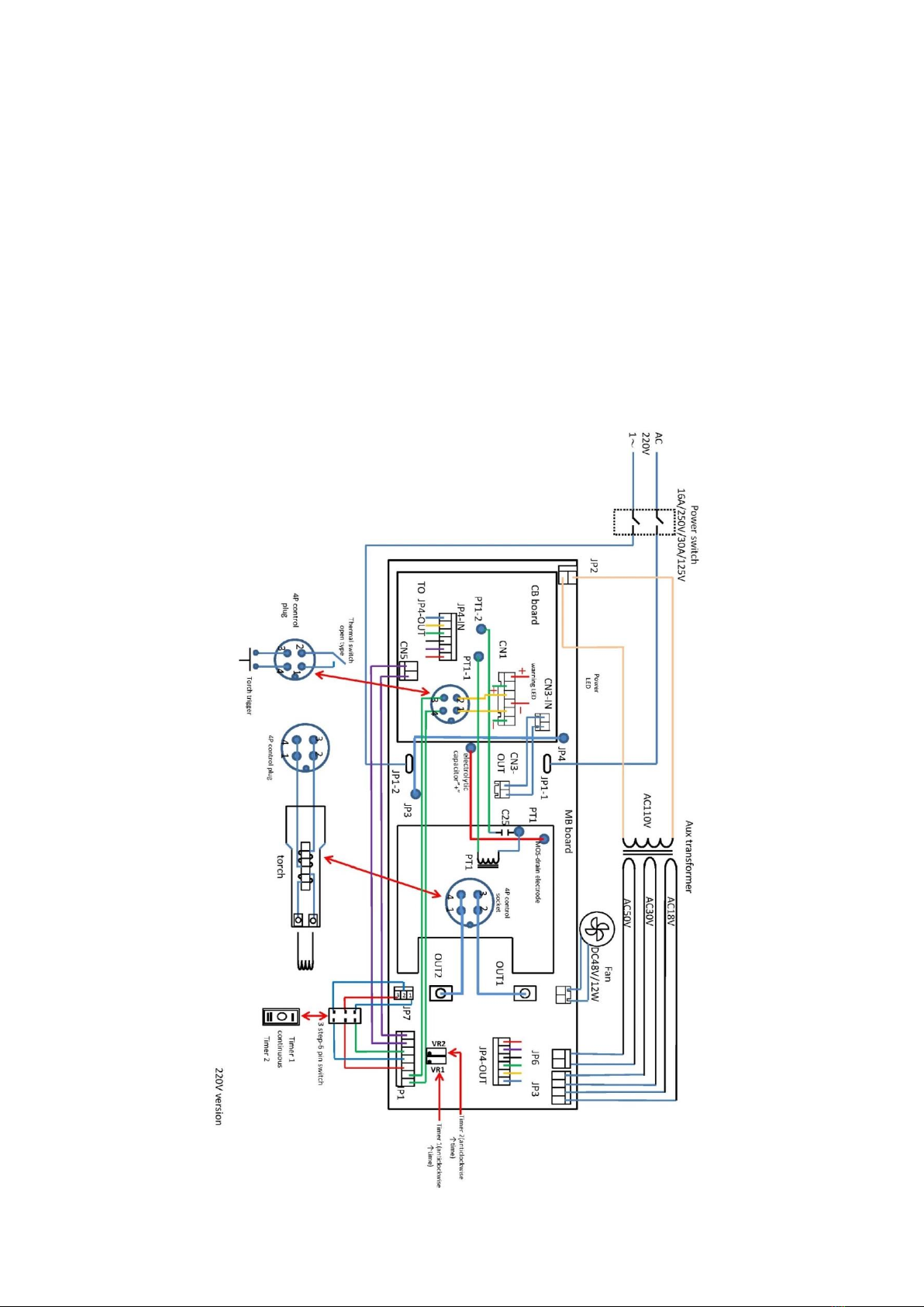
12. SCHEME ELECTRICAL
13.

INSTRUCTIONS FOR STORAGE AND TRANSPORT
The device should be stored at -10 ° C to + 40 ° C and relative humidity 80% free of corrosive fumes and dusts. Transportation of packaged
devices should be covered means of transport. For transport the packaged unit must be secured against slipping and ensure the correct position.
14. COMPLETE SPECIFICATION
1. Induction Heater - 1 pc.
2. heater holder - 1 pc.
3. Set heating coils:
- 17 mm - 20 mm
- 24 mm - 28 mm
- flat 50 mm - flexible (for pipes and rods).
- for spot heating plate (round).
15. Warranty
Guarantee granted for a period of 12 months for business entities or consumers for 24 months from the date of sale.
The guarantee will be respected by the advertiser after the presentation of proof of purchase (invoice or receipt) and warranty card
inscribed with the product name, serial number, date of sale and point of sale bearing the stamp.
In the case of warranty repair should contact TECWELD, which will arrange the reception device by courier.
Shipments sent at the expense of TECWELD through other shipping companies will not be accepted!
The device transmitted to the complaint must be packed in the original carton, and protected by Styrofoam original fittings. TECWELD
company is not liable for damage caused by the heater during transport.
If you wish to discard this product, do not throw it with general household waste. According to the
WEEE Directive (Directive 2002/96 / EC) in force in the European Union for used electrical and
electronic equipment must be used methods of utilization.
In Poland, in accordance with the provisions of the Act of July 1, 2005. Waste electrical and
electronic equipment is prohibited to place together with other wastes of used equipment marked
with crossed out wheeled bin symbol.
The user who wishes to discard this product, it is obliged to return waste electrical and electronic equipment to a used equipment collection point.
Collection points are run
among others by wholesalers and retailers of equipment and the municipal organizational units engaged in waste collection.
These legal obligations have been introduced to reduce the amount of waste generated from waste electrical and electronic equipment and to
ensure an adequate level of collection, recovery and recycling of used equipment. Proper implementation of these duties is important especially
when the waste equipment contains hazardous components which have a particularly negative impact on the environment and human health.
TECWELD Peter Polak Tel. (48) 32 38-69-428 Fax: (+48) 32 38-69-434,
41-909 Bytom ul. Cross 3 E-mail: [email protected]
www.tecweld.pl
DECLARATION OF CONFORMITY
01 / INDI1 / 2018
TECWELD Peter Polak
41-943 Piekary Slaskie Street.
Emerald 21/3/6
Declare that the said product:
induction heater
Type: STORM-HEATER
Trade name: INDI-1
Manufacturer's trademark:
to which this declaration relates complies with the following directives of the European Union and
national provisions implementing the Directive:
LVD Low Voltage Directive 2014/35 / EU
EMC Electromagnetic Compatibility Directive 2014/30 / EU
and is compliant with the following standards:
BS EN 60204-1: 2010 Safety of machinery - Electrical equipment of machines - Part 1: General requirements BS EN 60204-1: 2010 Safety of machinery - Electrical equipment of machines - Part 1: General requirements
BS EN 61000-3-2: 2014-10 Electromagnetic compatibility (EMC) - Part 3-2: Limits - emission limit harmonic current BS EN 61000-3-2: 2014-10 Electromagnetic compatibility (EMC) - Part 3-2: Limits - emission limit harmonic current
(phase current up ≤ 16 A)
BS EN 61000-3-3: 2013-10 Electromagnetic compatibility (EMC) - Part 3-3: Limits - Limitation of voltage changes, voltage BS EN 61000-3-3: 2013-10 Electromagnetic compatibility (EMC) - Part 3-3: Limits - Limitation of voltage changes, voltage
fluctuations and flicker in public low-voltage supply, caused by the load of rated current phase <= 16 A attached
unconditionally
BS EN 61000-6-1: 2008 Electromagnetic compatibility (EMC) - Part 6-1: Generic standards BS EN 61000-6-1: 2008 Electromagnetic compatibility (EMC) - Part 6-1: Generic standards
-- Resistance environments: residential, commercial and light-industrial
BS EN 61000-6-3: 2008 / A1: 2012 Electromagnetic compatibility (EMC) - Part 6-3: Generic standards - Emission BS EN 61000-6-3: 2008 / A1: 2012 Electromagnetic compatibility (EMC) - Part 6-3: Generic standards - Emission
standard environments: residential, commercial and light-industrial
Year affix the CE mark on the device: 2015
Bytom, dn. 05/01/2018 Peter Polak
(Signature of authorized person)
Table of contents
Popular Heater manuals by other brands


Beko
Beko CLEARPOINT S040 TWC Control Instructions for installation and operation

KING
KING RH Series installation manual

Space-Ray
Space-Ray LTU Series Installation and operation instructions

Singer
Singer SCQH-20 instruction manual

Holmes
Holmes Odor Grabber HAP201 owner's guide

Sonnenkonig
Sonnenkonig LIMA user manual