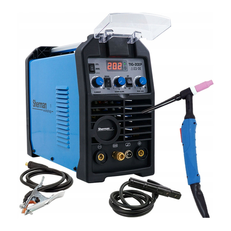
Sherman DIGITIG 206P User manual

1
V1.2 16.03.08
USER MANUAL
WELDING INVERTER
Sherman DIGITIG 206P AC/DC
WARNING!
Before installing and commissioning the device, you must read this instruction
1.
GENERAL NOTES
Launch and operation of the device can be made only after a thorough reading of this manual.
Due to continuous technical development unit, some of its features may be subject to modifications
and performance may differ in detail from the descriptions in this manual. This is not a device error,
but the result of progress and continuous work of modification of the device.
Damage to the appliance caused by improper handling causes the loss of warranty. Any alteration of
the charger are forbidden and result in loss of warranty.
2.
SECURITY
Equipment operators should possess the necessary qualifications entitling them to perform welding
work:
•
should be an electric welder welding electrodes coated and coated gas,
•
know the rules of SAFETY operation of power equipment such as welding machines and auxiliary
powered electricity,
•
know the rules of SAFETY when handling cylinders and installation of compressed gas (argon), • be
familiar with the content of this manual and operate in accordance with its intended purpose.

2
WARNING
Welding can endanger the operator and other people in the vicinity. Therefore, during welding
should keep special precautions. Prior to welding, you should be familiar with the
OCCUPATIONAL HEALTH and SAFETY regulations in force at the place of work.
At the time of the electric arc welding methods MMA WELDING and TIG WELDING, there are the
following:
• ELECTRIC SHOCK
• NEGATIVE EFFECTS OF THE ARC TO THE EYES AND SKIN MAN
• POISONING IN PAIRS AND GASES
• BURNS
• RISK OF EXPLOSION AND FIRE
• NOISE
To prevent electric shock:
• connect the device to the technically efficient electrical installation at the right protection and the
effectiveness of the reset (additional fire protection); check and correctly connected to other
network devices at the place of work the welder,
• current wires mounted on the unit is switched off,
• do not touch at the same time, non-insulated part of the electrode holder, electrode and work piece,
in this case,
• do not use the handles and current lines of the damaged insulation,
• in terms of specific risk electric shock (work in environments with high humidity and containers
closed) work with an Assistant supporting the work of the welder and for security, used clothing
and gloves with good insulation properties,
• if you notice any irregularities, please contact your competent people to remove them,
• Operation is prohibited with sacks, the guards.
Preventing the negative impact of the electric arc to the eyes and skin:
• Use protective clothing (gloves, apron, leather shoes),
• Use shields or protective helmets with properly selected filter
• Use protective curtains made from non-combustible materials and properly match the color scheme
of the walls absorbing the harmful radiation.
Preventing food poisoning in pairs and gases that react during welding with coating electrodes
and evaporation of metals:
• Use ventilation and extraction systems installed in positions with limited air exchange,
• Use compressed air to clean the air in a confined space (tanks), • Use masks and respirators.
Prevention of Burns:
• Use suitable protective clothing and footwear to protect from burns from radiation and spatter,
• Avoid dirt clothing grease and oils that may lead to inflammation. Explosion prevention and fire:
• It is prohibited to operate the unit and welding in explosive or fire,
• Welding position should be equipped with fire-fighting equipment,
• Welding position should be located at a safe distance from flammable materials.
Prevention of the negative effects of noise:
• Use earplugs or other protection against noise, • Warn about the danger of people nearby.
WARNING!
Do not use power source for defrosting frozen pipes.
Before starting the machine:
• Check the condition of the electrical and mechanical connections. It is prohibited to use handles and
wire current at the damaged insulation. Faulty insulation and cable handles current risk electric
shock,
• Ensure appropriate working conditions. Provide the right temperature, humidity and ventilation in the
workplace. In addition to enclosed spaces protected from rain,

3
• Put the charger in place for its ease of use.
People that support drop should:
• have the power to electric arc welding with coated electrodes and TIG
• know and comply with the occupational safety and health applicable when carrying out welding work,
• use proper protective equipment, specialized: gloves, apron, rubber boots, shield or helmet welding
stationary filter
• be familiar with the content of this manual and operate the place in accordance with its intended
purpose. Any repair of the device may be made only after disconnecting the plug from the
electrical outlet.
When the device is connected to the network it is not allowed to touch the bare hand or by damp
clothing no elements making up the welding current circuit.
It is forbidden to remove the guards outside at the device on the network.
Any alteration of the charger on its own is prohibited and may constitute a deterioration of security
conditions.
Any maintenance and repair may only be performed by qualified persons in compliance with the
conditions for safety of electrical equipment.
It is prohibited to the operation of welding in explosive or fire!
Welding position should be equipped with fire-fighting equipment.
After you complete the power cord, disconnect the device from the network.
These risks and the General principles of HEALTH and SAFETY at WORK do not cover all the issues
of safety at work the welder, because it does not take into account the specificities of the work
place. Important are complemented by on-the-job HEALTH and SAFETY instructions, training and
briefings provided by the supervisors.
3. GENERAL DESCRIPTION
DIGITIG 206 p AC/DC is used for manual welding with coated electrodes structural steels AC
and (MMA) and steel and non-ferrous metals established electrode in inert gas (TIG). In the design
and construction of the device uses the latest advances in technology, PWM (pulse width modulation)
and IGBT modules (with bipolar transistors insulated-gate), which resulted in that the welder is
characterized by small size and low weight.
DIGITIG 206 p AC/DC has a static arc. Has the functions of ARC FORCE, build-up and
downslope, pre flow and post flow gas and adjustable pulse parameters. The device is also equipped
with intelligent security overload, overvoltage and thermal. If you have previously described event
alarm LED indicator lights on the front panel and the disabled will be output. This leads to the self
security of the device and to extend its service life.
Function ARC FORCE
ARC FORCE function allows you to adjust the dynamic range of the welding arc. The shortening of
the length of the arc is accompanied by an increase in welding current, resulting in stabilizing the
arc. Decreasing the value will give you soft arc and less depth of penetration, while increasing the
value causes a deeper penetration and the possibility of submerged arc welding. With large values of
the ARC FORCE can be welded together by keeping the bow with a minimum length and high speed
melting electrode
MMA-welding coated electrode (Manual Metal Arc welding);
PWM-pulse width modulation (Pulse-Width Modulation);
IGBT — bipolar with insulated-gate (Insulation Gate Bipolar Transistor)
TIG-welding of tungsten electrode in argon (Tungsten Insert Gas welding)
4. TECHNICAL SPECIFICATIONS
4.1 Welder

4
Supply voltage AC 230V 50 Hz
The maximum power consumption MMA: 6.6 kVA, TIG: 4.2 kVA
Rated output/duty cycle MMA: 160 A/40% TIG 200 A/40%
Nominal voltage without load 60 V
Maximum current consumption MMA: 30 A, TIG, 30 A
Network security 16 A
The weight of the 14 kg
The dimensions of the 420 x 170 x 350 mm
Degree of protection IP21S
Class application
4.1.1 Ranges parameter adjustment
Pre flow gas 0.1-10 s
Post flow gas 0.5-15 s
The current build-up 0-10 s
Downslope 0 to 15 s
The starting current 5-160 A
Welding current MMA: 10-160 and TIG: 5-200 A
Electricity basics 5-200 A
Crater current 5-200 A
Pulse frequency 0.2-200 Hz
Pulse duration 10-90%
AC Frequency 20 – 250 Hz
AC Balance 15-85%
ARC FORCE 0-40 and
Spot time 0.5-10 s
4.2 Torch
The type of handle T-26
The maximum current capacity 200 and
Airflow 10-20 l/min
ARC Non-Contact Type (HF)
The length of the 4 m
Duty cycle
Duty cycle is based on a period of 10 minutes. 40% duty cycle means that after 4 minutes of
operation the device is required 4-minute break. The duty cycle of 100% means that the device can
work continuously, without interruption.
Please note! Heating test has been carried out at a temperature of ambient air. Duty cycle at 40 ° C
has been determined by simulation.
Degree of protection
IP specifies the extent to which the device is resistant to ingress inside the solids and water. IP21S
indicates that the device is suitable for working in confined spaces and is not suitable for use in the
rain.
Class application
Class application means that the device is suitable for use in areas with an increased danger of
electric shock.

5
5. DESIGN AND FUNCTION
The basis for the construction of processing system of electricity welding machines are electronic
circuits made in IGBT technology to work in the frequency range above 200 kHz.
The principle of operation is based on rectification voltage single phase mains to DC voltage,
converted the received voltage on the rectangular frequency, voltage transformation in the scope
required by the welding process and then restart after voltage on received voltage.
6. THE CONNECTION TO THE MAINS
1. The device should be used only in the single phase power, three wired, with a grounded
(earthed) neutral.
2. Inverter rectifiers DIGITIG 206 p AC/DC are designed to work with the network 230V 50 Hz 16A
fuse protected. The power supply should be stable, no voltage drops
3. The device is equipped with a power cord. Before connecting the power supply, make sure that
the power switch (6) is in the OFF position (off).
7. PREPARE YOUR MACHINE FOR
If you store or transport the device at low temperatures before starting to work to bring the
device to the right temperature!
7.1 method of MMA
Tips for welding cables must be connected to sockets (1) and (2) located on the front panel so that
the electrode holder was appropriate for a given electrode pole. The polarity of the connecting cables
depends on the type of the used electrodes and is given on the packaging of electrodes. Clamp return
line should be carefully stored on the puddle. Connect the mains plug to a wall socket 230V 50 Hz.

6
7.2 TIG
Current clamp holder should be connected to the socket for negative polarity (2), screw the handle
control plug into the socket (4), and the gas connection to the socket coupler (3). Gas hose with
regulator and must be attached to the gas nozzle (5) located on the back of the housing. The positive
pole (1) connect with the material welded using wire with tick-borne encephalitis. Connect the mains
plug to a wall socket 230V 50 Hz.
8. A DESCRIPTION OF THE FUNCTION PRZEŁACZNIKÓW AND KNOBS
8.1 Front and rear Panel
1. Positive polarity
socket

7
2. The socket the polarity negative
3. Protective gas port
4. Control socket handle
TIG WELDING
5. Protective gas connection
6. Main switch
8.2 Control Panel
(A) -display of welding parameters
The display indicates the parameters during their set and during welding. When lit up, the
corresponding LEDs on the side of the display indicates the unit parameter.
(B) -Setting of welding parameters

8
Adjustment of welding parameters is made by using the multifunctional knob located on the front
panel. Pressing the knob moves between the adjustable parameters. Currently adjustable parameter
is lighted the corresponding led, and appears on the display the current value of the parameter. Turn
the knob to the left to decrease and turn right to increase the value of the parameter. Pressing the
knob or leaving the knob stationary. 5 seconds to remember the changed parameter values.
(C) -Other features
Remote led becomes active when you connect the handle with the possibility of remote control
(option)
Electrode diameter check function is available in all welding methods. When you select the diameter
of the electrode the device will have spoken to sub-optimal setting of welding parameters by
inflammation of LEDs Note!.
(D) -Operating mode selection button (2T/4T/spot welding)
The button active only while welding TIG. Mode selection is indicated a corresponding led.
In 2T mode, pressing the switch in the handle of the handle will turn on the Ionizer and the ignition of
the arc. Welding is carried out with the switch. Release the switch to stop welding. In 4T mode,
pressing the switch in the handle of the handle will turn on the Ionizer and the ignition of the arc then
release the switch and lead welding with slow motion switch. Pressing the switch to stop welding.
In spot mode, after pressing the button you will start the welding and automatically stops after the set
time.
E-selection of welding methods
2
T
4
T
Spawanie punktowe
Zdalne sterowanie
Ś
rednica elektrody
Uwaga!
ARC FORCE / czas
spawania punktowego
Prąd spawania
Częstotliwość AC
Częstotliwość pulsu /
czas trwania impulsu
Narastanie prądu
Przedwypływ gazu
Prąd podstawy
Balans
Powypływ gazu
Prąd krateru
Opadanie prądu
Prąd początkowy

9
Button
used to select welding method. The choice of method is indicated a corresponding led.
8.3 protection against overheating
The power source is equipped with a thermal overload switch in the compression. When the
temperature of the welding will be too high, disconnect the welding current, the code appears on the
display E1 will start beeping to signal overheating. After falling back temperature will automatic reset
circuit breaker.
9.
PARAMETER SETTINGS
9.1
MMA Method
After selecting the MMA welding current adjustment is possible and the ARC FORCE.
9.2
TIG
The check button welding select TIG DC, TIG DC with pulse, TIG AC or TIG with pulse. Source
control mode button select the 2T, 4T or spot welding.
Adjustment of the welding current is possible immediately after the power is turned on. Turning
the control dial to change the welding current. After you set the appropriate values, you must press
the knob to confirm the settings. Leave the knob without movement by the 5s will automatically
confirm a setting.
To set the other parameters you must press the control dial until the led lights up the appropriate
parameter by turning the control dial to set the desired value. Confirm the setting by pressing the
control dial or waiting for 5s (auto-confirm a setting).
-
ARC FORCE (MMA)/spot time
Adjustment range 0 – 40A/0.5-10s
Tpre is a time post flow gas
Control range: 0.1-10 s
2
T
4
T
Spawanie punktowe

10
The is-the starting current
Range 5-160A
Tup-rise time currents
Adjustment range 0 – 10 s
IP-welding current
Range 5-160A (MMA)/05-200A (TIG)
IB-current base (only in welding with pulse)
Range 5-200A
Tdown-downslope time
Adjustment range 0-15s
If direct current crater
Range 5-200A
Tpost-post flow gas
Control range: 0.5-15s
Balance-Balance AC-the ratio of the duration of the halves of the positive to the negative
halves of welding current
Adjustable 15-85%
-Pulse frequency/pulse duration (the time of welding current Ip to
time of the current base of Ib) (only in welding with pulse)
Adjustment range 0.2-200 Hz/10-90%
10. WELDING
10.1 Welding coated electrode (MMA)
10.1.1 Initiation of the arc
Initiation of the arc when welding coated electrode is touched the electrode to the work piece, short
non-safety and isolation. In the case of the initiation of the arc electrodes whose lagging after set
creates a non-conductive slag should be initially cleaned top of the electrodes by repeatedly hitting a
hard surface until the contact with metal welded material.
10.1.2 Carrying out welding process
The check button to select welding method MMA. In this mode, the welding current adjustment is
possible and the ARC FORCE.
Adjustment of the welding current is possible immediately after the power is turned on. Turning
the control dial to change the welding current. After you set the appropriate values, you must press
the knob to confirm the settings. Leave the knob without movement by the 5s will automatically
confirm a setting.
10.2 Gas shielded Welding (TIG).
10.2.1 The initiation and conduct of welding in TIG welding
Device DIGITIG 206 p AC/DC is fitted with Ionizer for non-contact arc.
To initiate the arc in dwutaktu mode, you must approach the electrode to the work piece at a distance
of 2 millimeters and press the button in the handle of the burner to turn on the Ionizer. After the
correct initialization of the arc welding lead control-button. Release the button at the handle starts the
downslope phase and the completion of the welding process.
/

11
To initiate the arc in czterotaktu mode, you must approach the electrode to the work piece at a
distance of 2 millimeters and press the button on the handle of the burner to turn on the Ionizer. After
a valid ARC, you can release the button and the welding lead with a slow motion button. To complete
the welding press and release the button on the handle.
10.2.2 TIG welding in 2T mode :
0: Press and hold the handle. Starts the flow of shielding gas;
0~:t1 Pre flow of gas;
T1~t2 Ignition of the arc welding current builds up from the minimum value to the set value
welding current.
If the pulsator is enabled, the current is modulated.
T2~t3 During welding the handle should stay down;
Note: If the pulsator is enabled, the output current pulses if the pulsator is turned off,
welding current is fixed to
T3: Release the handle button, the welding current begins to fall. If the pulsator is enabled,
decreasing electricity is modulated;
T3~t4 Welding current drops to the minimum value, the arc is suppressed;
T4~t5 Post flow gas.
T5:
Solenoid valve closes the gas flow, completion of welding.
10.2.3 TIG welding in 4T mode:
0: Press and hold the handle. Starts the flow of shielding gas;
0~:t1 Time pre flow. Adjustment range: 0 ~ 1.0 sec;
T1: Ignition of the arc, is start current;
T2: Release the button of the handle starts the current buildup to the set current value
welding.
If enabled, current pulser is modulating;
T2~t3 Rise time currents;

12
T3~t4 The welding process;
Note: If the pulsator is enabled, the output current pulses if the pulsator is disabled, the output
current is a constant value;
T4: Press the handle. Welding current starts to fall to the current crater. If
the pulsator is enabled, falling power is modulated;
T4~t5 Downslope;
T5~t6 Crater current;
T6: Release the handle. The arc is dimmed, spewing shielding gas;
T7: Solenoid valve closes the gas flow, completion of welding.
10.2.4 Spot welding
In spot mode, source control is done as in 2T mode, after the set time welding end of welding will
occur automatically.
11. BEFORE YOU CALL SERVICE
In the case of a malfunction of the device, before sending the welder to the site you should check out
the list of basic failure and try to remove them.
Any repair of the device may be made only after disconnecting the plug from the electrical outlet.
Please note! The device is not sealed and you can remove the cover of the welder to remove glitches.
Symptoms of Ways to remove
Control Panel does not
light up, the fan is not
working, no output voltage
1. Make sure that the switch is in the ON position
2. Check the security and network voltage
3. Remove the cover and check the connection of all the electrical
plug-ins inside the machine
Control Panel lights up, fan
not working, no output
voltage.
1. Verify that the device is not connected to a network with a higher
voltage. If so, connect the 230V and turn on again
2. The supply voltage is unstable and the fuse is enabled. Turn off
the machine for 2-3 min and turn on again
3. Short lived on and off switch resulted in the inclusion of
fuse. Turn off the machine for 2-3 min and turn on again
4. there has been other damage requiring repair by an authorized
service
Control Panel lights up, fan
runs, the problems of the
ignition arc
1. check the torch, replace wear parts if they are worn
Control Panel lights up, fan
runs, the machine ignites the
arc
1. Check the terminals and correct electrical conductivity electrode
cable and mass
2. Check the connection of the TIG torch to the unit, pay attention if
any plug pins on the socket are not broken or do not seize.
3. To spin the TIG torch handle and check that the switch in the
handle is working
Control Panel lights up,
fan runs, the display
shows E1
1. The device is overheated. Wait a few minutes. When the light
goes out, the message E1 and continue welding.
Unsatisfactory quality of
welds in welding MMA, the
electrode stick to the work
piece
1. Check the polarity of the connecting cables
2. Check that the electrode is not moist. Replace the electrode.
3. Welder is powered by generator or by a long extension cord is
too small. Connect the unit directly to the mains

13
Unsatisfactory quality of
welds in welding TIG
1. Replace wear parts. Change the tungsten electrode or gas
cylinder on the higher-quality materials
2. Check that the shielding gas flows with the appropriate
intensity
3. Check the gas supply hose, hose couplings, steel connection
status and improved quick couplers
4. Check the cylinder regulator/reductor.
12. OPERATING MANUAL
Operating the system DIGITIG 206 p AC/DC should take place in an atmosphere free from abrasive
and dusty. Do not set the device in dusty, near working grinding machines etc. Dust and pollution
control boards metallic filings, wires and connections inside the equipment can lead to short circuits,
and consequently damage the welder.
Avoid operation in environments with high humidity, and in particular the presence of dew on the
elements of metal.
In the event of the occurrence of dew on the elements of metal for example. After the introduction of a
cool device to a warm room, wait until it disappears. It is recommended that if operation of the welding
machine in the open air, placing her under a roof to protect against adverse weather conditions.
Device DIGITIG 206 p AC/DC should be operated under the following conditions:
- changes the effective value of the supply voltage not greater than
10%
- ambient temperature from-10 ° c to + 40 ° c
- atmospheric pressure of 860 to 1060 hPa
- relative humidity of ambient air not more than 80% of the
- height above sea level up to 1000 m parts list the TIG torch
consumables T-26:
LP
The name of the
1 Tungsten electrode
2 Collet T-26
3 The current connector T-26
4 Gas nozzle T-26
For the full list of consumables and spare parts is available on the website www.tecweld.pl and at
TECWELD. There is a possibility of direct purchase of these parts.
13. MAINTENANCE MANUAL
As part of the daily service keep the place clean, check the status of the external connections and the
condition of the wires and electric cables.
Regularly wear parts.
Periodically clean the device inside through the scavenge with compressed air to remove dust and
metallic filings of controls and wires and electrical connections.
Not less than once every half a year to be made a general review of the condition of the electrical
connections, in particular:
- State fire protection
- insulation
- the State security system
- correct operation of the cooling system
14. INSTRUCTIONS FOR STORAGE AND TRANSPORT
The device should be stored at a temperature of-10 ° c to + 40 ° c and a relative humidity of up to
80% of free from corrosive fumes and dust. Transportation of packaged devices should be carried out

14
in covered means of transport. To transport the packed unit must be protected against displacement
and provide them with the right position.
15. THE SPECIFICATION OF A SET OF
1. Retrieved DIGITIG 206 p AC/DC 1 PCs. 2. TIG
welding holder 1 PCs. 3. Ground cable with clamp tick-
borne encephalitis 1 PCs.
4. instruction manual 1 PC. 5. Pack 1 PCs.
16. WIRING DIAGRAM
17. WARRANTY

15
Warranty is granted for a period of 12 months for entities carrying on economic activities or 24
months from the date of sale to the consumer.
Warranty will be respected after the presentation by the advertiser of proof of purchase
(invoice or receipt) and the warranty card with the typed name of the product, the serial
number, the date of sale and bearing the stamp of the point of sale.
In the case of warranty repair faulty device should be sent to the company TECWELD shipping
company GLS.
Consignments sent at the expense of the company TECWELD through other shipping
companies will not be accepted!
Place must be delivered together with cables. Complaints without the gun will not be
considered.
The device sent to the complaint must be packed in the original carton and protected the
original fittings styrofoam boards. The company TECWELD is not responsible for damage to
the welding machines arising during transport.
If you are going to get rid of this product, do not dispose of it together
with ordinary household waste. According to the WEEE directive (Directive 2002/96/EC)
applicable in the European Union for used electrical and electronic equipment should be used
separate ways of disposal.
In Poland in accordance with the provisions of the Act of 1 July 2005. about the waste electrical
and electronic equipment is prohibited including waste waste tagged crossed trash.
A user who intends to get rid of this product, is obliged to return the waste electrical and electronic
equipment to the point of collecting used hardware. Collection points are m.in. by wholesale and
retail vendors of equipment and by municipal agencies active in the field of receiving waste.
These statutory duties have been introduced in order to limit the amount of waste generated
from the waste electrical and electronic equipment, and ensure an appropriate level of the
collection, recovery and recycling of waste. The correct implementation of these duties is
important especially when used equipment contains hazardous ingredients, which have a
particularly negative impact on the environment and human health.
Table of contents
Other Sherman Welding System manuals
Sherman
Sherman TIG 202P User manual
Sherman
Sherman DUALMIG 210 S3 User manual

Sherman
Sherman 50 Cutter User manual
Sherman
Sherman TIG 210 AC / DC Pulse User manual

Sherman
Sherman 40 Cutter User manual
Sherman
Sherman DIGIMIG 225GDS User manual
Sherman
Sherman MIG 230/2 User manual
Sherman
Sherman DIGITIG 200GD User manual
Sherman
Sherman DIGIMIG 200 PULSE User manual
Popular Welding System manuals by other brands
Kipor
Kipor KDE180XW Operator's manual
Demtech
Demtech Pro-XMP 605-0102/XMP/A Operator's manual

Leister
Leister TWINNY T7 Repair instructions
Weco
Weco Pioneer 321 MSR instruction manual

Miller Electric
Miller Electric Millermatic 350 owner's manual
EWM
EWM Phoenix 351 Expert 2.0 puls MM FDW operating instructions

