Sherwood Scientific 420 User manual

425 89 001 Issue 6 23rd March 2012 ECN 736
G:\DOCUMENT CONTROL\Manuals\Flame\425\42589001 M420 & M425 Service Manual Issue 6.doc
Sherwood Scientific Ltd
Model 420 & 425 Flame Photometer
Service Manual
Sherwood Scientific Ltd.
1 The Paddocks
Cherry Hinton Road
Cambridge
CB1 8DH
England
Tel. +44 (0)1223 243444
Fax. +44 (0)1223 243300
e-mail: info@sherwood-scientific.com
http://www.sherwood-scientific.com

Model 420 & 425 Flame Photometer
425 89 001 Issue 6 23rd March 2012 ECN 736 2
Contents
1 Introduction
1.1 Introduction ................................................... 5
1.2 Intended Use ................................................... 5
2 Positioning and Services
2.1 Electrical Supply ................................................... 6
Fuel ................................................................. 6
Air ................................................................. 6
Waste Container ................................................... 6
2.2 Site Conditions ................................................... 6
3 Performance Characteristics and Specifications
3.1 Specification ................................................... 7
3.2 Warm Up ................................................... 7
3.3 Environmental Conditions ...................................... 7
Temperature ................................................... 7
Humidity ................................................... 7
Installation Category ...................................... 7
4 Front Panel Controls and Indicators
4.1 Controls ................................................... 8
- Set + ................................................................. 8
Blank ................................................................. 8
Single/Dual and Element Selection ........................ 8
Peak/Ref./Cont. .................................................... 8
Print .................................................................. 9
Power 0/1 .................................................... 9
4.2 Indicators .................................................... 9
Readout .................................................................. 9
CAL (Ch1 and Ch2) ....................................... 9
Element Selection Indicators ......................... 9
Single ................................................................... 9
Dual ................................................................... 9
Peak ................................................................... 9
Cont. ................................................................... 10
Ref. ................................................................... 10
Measure ................................................................... 10
Flame on ..................................................... 10
Power on ..................................................... 10

Model 420 & 425 Flame Photometer
425 89 001 Issue 6 23rd March 2012 ECN 736 3
Contents
4.3 Rear Panel Controls and Connections ........... 10
Channel 1 & 2 Data Outputs ………………. 10
RS232/Printer Output ....................................... 10
External Device Output ....................................... 10
Power ................................................................... 10
Gas ................................................................... 11
Air ................................................................... 11
Air Regulator ..................................................... 11
5 Cleaning and Maintenance Procedures
5.1 Cleaning and Maintenance Procedures ............ 12
6 Instrument Description
6.1 General ................................................................... 13
6.2 Main Printed Circuit Board .......................... 13
Signal Sensing …………………………………… 13
Flame Sensing ......................................................13
Ignition Timing ......................................................13
Fuel Solenoid Control ........................................ 13
7 Replacement Procedures
7.1 Printed Circuit Board ........................................ 14
7.2 Solenoid Valves ......................................................14
Replacing the Coils ........................................ 14
7.3 Restrictors ......................................................14
7.4 Gas Pressure Regulator ........................................ 14
7.5 Air Pressure Switch ........................................ 15
7.6 Ignitor ....................................................................15
7.7 Flame Sensor ......................................................15
7.8 Photocell ......................................................16
7.9 Filters ....................................................................16
Filter Factors ......................................................17
8 Spares
8.1 Ordering Information ......................................................18
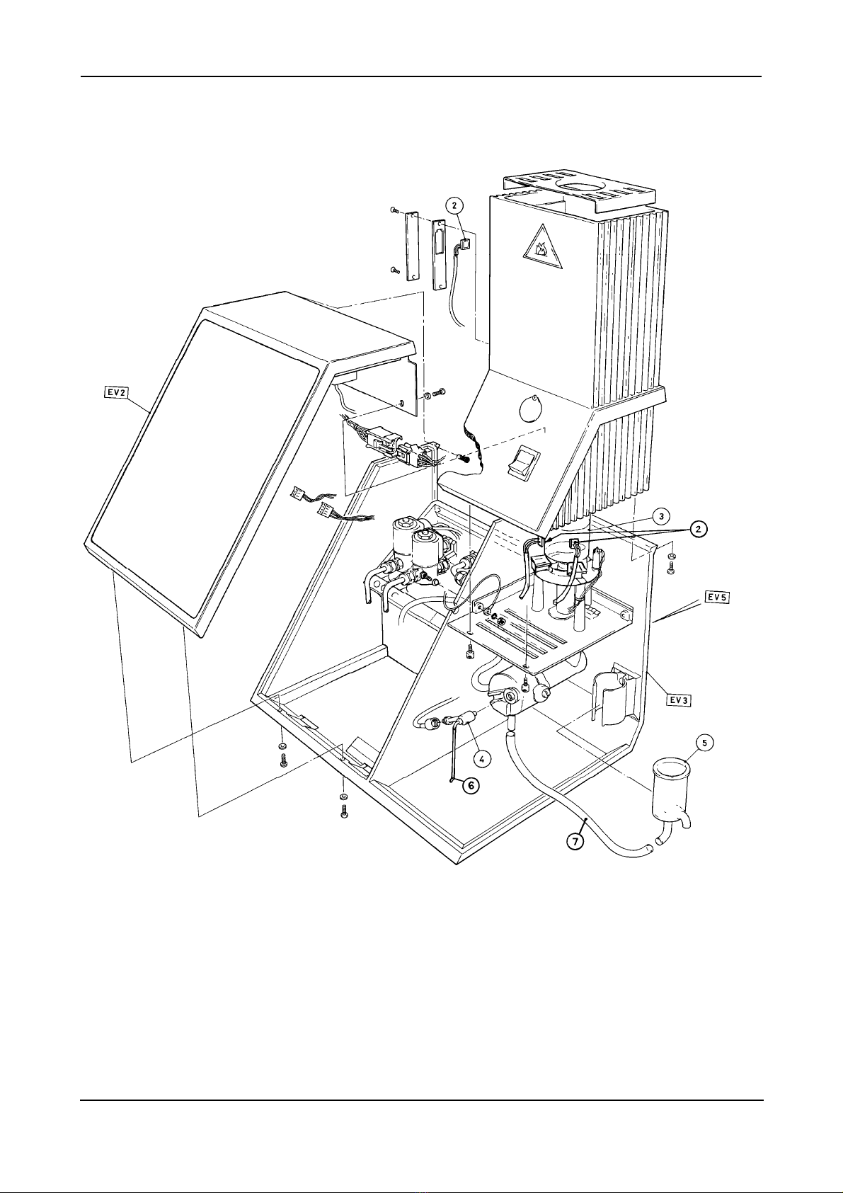
EV1 General Arrangement ........................................ 19
EV2 Front Panel Assembly ........................................ 22
EV3 Main Chassis Assembly ........................................ 24
EV4 Gas Chassis Assembly ........................................ 26
EV5 Rear Mounted Components .......................... 29

Model 420 & 425 Flame Photometer
425 89 001 Issue 6 23rd March 2012 ECN 736 4
Contents
Exploded Views
EV1 General Arrangement, upto s/n 20410 ............ 20
EV1a General Arrangement, s/n 20411 on ……… 21
EV2 Front Panel Assembly ........................................ 23
EV3 Main Chassis Assembly ........................................ 25
EV4 Gas Chassis Assembly ........................................ 27, 28
EV5 Rear Mounted Components .......................... 30
Figures
420 98 002 Gas Piping Block Diagram ........... 31
420 98 006 Wiring Schematic ......................... 32, 33

Model 420 & 425 Flame Photometer
425 89 001 Issue 6 23rd March 2012 ECN 736 5
1 Introduction
1.1 Introduction
The Sherwood Scientific Model 420 & 425 Flame Photometers are dual channel low temperature
Flame Photometers designed to be used for the simultaneous determination of two elements from three
(M420) or four (M425) possible elements, Sodium (Na) and Potassium (K), Lithium (Li) or Calcium
(Ca) (M425 only). These instruments also have the benefit of an Internal Standard using a Lithium
(Li) signal to eliminate interference due to variation in dilution ratios (where a continuous Diluter is
used) as well as variability in the characteristics of the flame photometer itself.
The Model 420 & 425 can also function as a single channel instrument for the determination of Li
samples as well as Na or K or Ca (M425 only).
1.2 Intended Use
The unit is intended for use by persons knowledgeable in safe laboratory practices. If the unit is not
used in accordance with the Instructions for use, the protection provided by the equipment may be
impaired.
The Operator’s Manual 425 91 001 contains complete instructions for setting up and using the
instrument.
WARNING The instrument is designed to be grounded through the power supply lead for safe
operation. For the safety of operating personnel and optimum performance make sure that the
instrument is only connected to a 3-pin socket that has an effective earth connection. If you are in
any doubt about the safety of your electrical supply system consult a competent, qualified
electrician.
Sherwood Scientific and its authorised Distributors and Agents consider themselves responsible for
the effects of safety, reliability and performance of the instrument only if:-
Assembly operations, extensions, re-adjustments, modifications or repairs are only carried out by
persons authorised by them.
The electrical installation of the relevant room complies with IEC requirements or the local authority
code.
The equipment is used in accordance with the instructions for use.
This Service Manual covers the Model 420 and Model 425 Flame Photometer and is provided for the
use of engineering personnel who have received training on this products.
The information contained within this manual was correct at the time of going to print. However,
Sherwood Scientific’s policy is one of continuous product improvement and the right to change
specifications, equipment and maintenance procedures at any time, without notice, is reserved.
This manual is copyrighted, and all rights are reserved. No part of this manual may be reproduced by
any means or in any form without prior consent in writing.

Model 420 & 425 Flame Photometer
425 89 001 Issue 6 23rd March 2012 ECN 736 6
2 Positioning and Services
2.1 Services Required
Electrical Supply
An AC supply between 100V and 240V ±10%, at 50 or 60 Hz, is required. The instrument is powered
from an external power supply, which will accommodate these voltages without any need to adjust the
instrument.
Fuel
A supply of high grade propane, butane or propane/butane mixture regulated at the cylinder to
2.1kg/cm² (30psig), with flow rate a minimum 0.4l/min.
All fuels to be free of heavy hydrocarbon deposits.
(NOTE. Lower grade fuel can be used, however, operation outside the specification can be expected).
Air
A supply of clean dry, oil free air at 1 kg/cm² (14psig), with flow rate of 6 l/min. As supplied by a
Model 851 Air Compressor. Maximum inlet pressure 2.1 kg/cm² (30psig).
The stability of the readings from the instrument, especially at high gain, depends on a smooth
aspiration of the sample. This can be disturbed by droplets of condensation coming from the air
compressor, where the compression/expansion causes significant condensation in humid atmospheres.
If condensation problems arise a Model 856 Air Compressor should be used, which has a water
separator fitted.
Waste Container
A sink or waste container situated to the right of the instrument will ensure the minimum length of
waste tubing. Do not use a waste container with high sides as this will cause the drain tube to be lifted
above the level of the constant head drain.
2.2 Site Conditions
WARNING Under no circumstances install the Flame Photometer beneath overhanging
cupboards. There must be at least 1 metre of clear space above the chimney.
For optimum performance , the instrument should be installed in accordance with the following
conditions:-
1/ The environment must be clean and free from dust.
2/ The instrument must be places on a strong, level worktop free from vibration.
The Model 420 & 425 require approximately 500mm x 500mm of bench space,
which includes an area in front for solutions and clearance at the rear for tubing.
3/ Avoid sites that expose the instrument to direct sunlight or draughts.
4/ To meet the specification the ambient temperature must be within the range +10°C to
+35°C. The maximum relative humidity must be no greater than 85%, non
condensing.

Model 420 & 425 Flame Photometer
425 89 001 Issue 6 23rd March 2012 ECN 736 7
3 Performance Characteristics and Specifications
3.1 Specification
For specification refer to Operators Manual Section 4.1, 4.2, 4.3 & 4.4.
3.2 Warm Up
To achieve the stated specification the flame must be alight for a minimum of 15 minutes, with diluent
being aspirated.
3.3 Environmental Conditions
Temperature
Operating +10°C to +35°C
Transportation -10°C to +45°C
The instrument specification will be unaffected by an ambient temperature change of 4°C (or less) per
hour, within the range +10°C to +35°C, with a maximum of 7°C shift during 8 hours.
Humidity
Operating 85% maximum at +35°C
Transportation 95% maximum at +45°C (non condensing).
Installation Category
Installation category 1.

Model 420 & 425 Flame Photometer
425 89 001 Issue 6 23rd March 2012 ECN 736 8
4 Front Panel Controls and Indicators
4.1 Controls
‘-’ ‘Set’ ‘+’
Primarily used in the Calibration process.
Secondary functions include date and time, and filter factor setting.
‘Blank’
Forces the instrument to zero all channels.
Must be used at start-up and after a change of Peak/Cont., Single/Dual or Element selection.
May be used at any time during a measuring session at the users discretion.
A long press at any time will reset to default settings and put the instrument into start-up blanking
mode.
‘Single/Dual’ and Element selection
Used at start-up to choose Single or Dual channel operation.
Used to select particular elements by ‘toggling’ through the sequence: -
M420
Na & K, Na & Li, Na, K, Li.
M425
Na & K, Na & Ca, Na & Li, Ca & K, Ca & Li, Na, Ca, K, Li.
When in “Ref” Mode with Li Internal Standard, Li cannot be measured and will not be selectable.
When pressed during a measurement session the instrument will automatically require Blanking and
Calibration.
‘Peak/Ref./Cont.’
Used at start-up before Blanking to choose measurement mode.
Peak has the instrument sense when a steady reading has been achieved and freeze the display.
Ref. uses signals from the Lithium channel as an internal reference. Can be used with Peak or Cont..
When the Internal Standard is invoked with the ‘Ref.’ mode, this uses the signal from the Li detector
to scale the readings from the other detector(s) to allow for external effects such as flame
disturbances, changes in dilution, nebuliser uptake rate, etc.
It works by adding a known concentration, Co, of Li to the diluent of the sample. The Li signal is
constant at Co if all the external effects are constant. If the Li signal goes up to C1then the other
signals would go up erroneously unless scaled down by the factor of Co/C1and vice-versa if the signal
goes down. The ratio is only applied to readings in ‘Measure’ mode.
To use this mode the blank, calibration and samples will have to be in a solution with the known
concentration, Co, in the diluent.
Cont. displays reading in real-time.
Sequence is:- ‘Peak’ , ‘Peak & Ref.’ (default mode), ‘Cont.’, ‘Cont. & Ref.’ and back to ‘Peak’.

Model 420 & 425 Flame Photometer
425 89 001 Issue 6 23rd March 2012 ECN 736 9
Front Panel Controls and Indicators
continued
‘Print’
Used to cause an output to RS232 serial port (connected to a printer, computer or data logger).
Operates the same in both ‘Cont.’ and ‘Peak’. Sample must be introduced before ‘Print’ is pressed.
Short, long or double presses produce different sample identification in output format:-
RRR Repeat sample - press twice
QQQ Quality control sample - long press
Power 1/0
The rocker switch that switches the AC power supply on (1) and off (0). When the unit is switched on,
the power LED is illuminated and an ignition cycle is initiated. When switched off the flame is
extinguished and the AC supply to the unit switched off.
The compressor must be switched on before the flame photometer is switched on, otherwise the air
pressure switch will not activate and allow fuel to flow and consequently the flame to light. Also the
compressor must be left on until the unit is switched off.
4.2 Indicators
All of the front panel indicators are LED’s mounted behind a flexible plastic overlay which provides
protection from the laboratory environment. Some windows are plain rectangles, others text legends.
Readout
Dual 3½ digit light emitting diode (LED) display, 12.5 mm high.
Display range 0 to 199.9.
NOTE If negative values are displayed the instrument is operating outside of the recommended
measurement range, or it is in between samples in continuous reference mode (i.e. Lithium reference is
absent).
‘CAL’ (Ch1 & Ch2)
‘CAL’ on a given channel starts to flash when the instrument automatically goes into calibrate after
successfully blanking.
‘CAL’ changes from flashing to steady when either:-
in cont. mode ‘Set’ is pressed for the second time in the calibration process.
in peak mode the internal part of the calibration process is complete.
Element Selection Indicators
‘Na’ is available when in Dual or Single mode on Ch1.
‘K’ is available when in Dual or Single mode on Ch2.
‘Li’ is available when in Dual or Single mode on Ch2 when ‘Ref’. is not selected.
‘Ca’ (M425 only) is available on Ch1 or Ch2, depending on which other element is selected in Dual
mode.
‘Single’
Is steadily illuminated when in Single Ch1 or Single Ch2 modes.
‘Dual’
Is steadily illuminated only when in Dual mode
‘Peak’
Indicates that Peak mode has been selected. ‘Peak’ and ‘Ref.’ can both be illuminated at the same
time.

Model 420 & 425 Flame Photometer
425 89 001 Issue 6 23rd March 2012 ECN 736 10
Front Panel Controls and Indicators
continued
‘Cont.’
Indicates that continuous measure mode has been selected.
‘Cont.’ and ‘Ref.’ can both be illuminated at the same time.
‘Ref.’
Indicates that reference mode has been selected.
‘Measure’
Illuminates when calibration is complete and instrument is ready to make measurements.
‘Flame on’
LED that illuminates when the flame is alight.
‘Power on’
Illuminates when the unit is switched on.
Rear Panel Controls and Connectors
4.3 Rear Panel Controls and Connectors
(see diagram page 30)
Channel 1 & 2 Data Outputs
Both these outputs carry a variable signal equivalent to a display reading of 199.0 on both channels.
When the instrument is in Clinical mode and when the display is in the lower range, for K and Li,
reading to two decimal places. The output is equivalent to 19.9.
The outputs can be connected to an Analogue/Chart recorder. The output is provided from the
Digital/Analogue converter.
RS232/Printer Output
This is a 9 pin D socket and the printer output cable (supplied) should be connected here. The other
end of the cable is a 9 pin standard RS232 ‘D’ connector, for serial printers and data logging devices.
External Device Output
This is a 6 pin miniDIN connector which enables the Model 420 & 425 to be connected to the Model
860 Autosampler.
Power
The Model 420 & 425 are supplied with a Universal External Power supply which can accommodate
100-240V AC input.

Model 420 & 425 Flame Photometer
425 89 001 Issue 6 23rd March 2012 ECN 736 11
Rear Panel Controls and Connectors
continued
Gas
¼ inch fuel inlet connector, permanently connected to the regulator inlet. The Model 420 & 425 will
operate satisfactorily on Propane and Butane. All fuels to be free of heavy hydrocarbon deposits and
regulated at the cylinder to a pressure of 2.1 kg/cm² (30psig).
NOTE The Model 420 & 425 need a primary regulator fitted to the gas cylinder, which differs
depending on the gas and cylinder configuration:-
Fuel Part number
Propane 001 08 234
Butane 001 08 732 for small Camping Gaz cylinders
001 08 733 for 7.5 Kg cylinders (caravan size)
001 08 439 for 15 Kg cylinders
NOTE The Propane regulator will allow both Propane and Butane to be used, as well as a mixture
(LPG).
The Butane regulator will not allow Propane to be used.
Air
¼ inch connector for the air inlet tubing from the air compressor outlet. A supply of clean air at a
minimum pressure of 1 kg/cm² at 6 litres/minute is required. Maximum inlet pressure 2.1 kg/cm²
(30psig). If condensation problems arise, a Sherwood M855 Air Compressor should be used, which
has a water separator fitted.
Air Regulator
Control to adjust the pressure of the air supply to 0.77 kg/cm² (11psig). The air pressure gauge
provides a visual indication of the air pressure.

Model 420 & 425 Flame Photometer
425 89 001 Issue 6 23rd March 2012 ECN 736 12
5 Cleaning & Maintenance Procedures
5.1 Cleaning & Maintenance Procedures
The Model 420 & 425 have been designed to allow customers to carry out all routine maintenance
procedures, e.g. Daily, Weekly, Monthly and Six Monthly. Refer to the Operators Manual for detailed
information. The various procedures are listed below: -
Section Procedure
8.2 Daily maintenance
8.3 Weekly maintenance
8.4 Monthly maintenance.
8.5 Six monthly maintenance
8.6 Nebuliser.
8.7 Cleaning the mixing chamber, burner and drain.
8.8 Cleaning the optical filters and glass chimney.
8.9 Voltage selection and fuse replacement.
8.10 Deproteinising or Disinfecting procedure.

Model 420 & 425 Flame Photometer
425 89 001 Issue 6 23rd March 2012 ECN 736 13
6 Instrument Description
6.1 General
This section describes the electrical and electronic circuits. The following PCB’s are fitted.
Title Part number Fitted to
Main PCB 425 65 001 Serial number 15542 onwards
Rear PCB 425 65 002 Serial number 15542 onwards
Except for the ‘power’ switch, the AC power supply components are mounted in the external power
supply or on the rear PCB. Other DC power supply components are mounted on the rear PCB, which
is located behind the rear panel. This PCB also contains the ignition and fuel control circuits. The
main PCB contains the amplifier, display and flame sensing circuitry.
6.2 Main Printed Circuit Board
Signal Sensing
M420
There are three photocells, each one dedicated to detecting one element via the appropriate filter Na, K
& Li. They are connected to the PCB via PL1 pins 2, 4 & 6 are K.
pins 1, 3 & 5 are Li.
pins 8, 10 & 12 are Na.
M425
There are four photocells, each one dedicated to detecting one element via the appropriate filter Na, K,
Li & Ca. They are connected to the PCB via PL1pins 2, 4 & 6 are K.
pins 1, 3 & 5 are Li.
pins 7, 9 &11 are Ca.
pins 8, 10 & 12 are Na.
Flame Sensing
The flame sensor is connected across input pins 2 and 3 of PL2. The resistance of the sensor is greater
than 10 MΩin the no flame condition, but falls to less than 1 ΜΩ in the flame on condition. This
causes the input at PL2, pin 2, to be pulled towards 0V. The output of comparator U4 goes high and
this signal passes to switch on D15 the ‘flame on’ indicator.
Ignition Timing
When the instrument is powered up, AC is supplied to the ignition unit for approximately 10 seconds,
which generates the sparks to ignite the flame.
Fuel Solenoid Control
Fuel is supplied to the burner during the ignition cycle, and for as long as the ‘flame on’ condition is
sensed. During the ignition cycle, the ignition timing circuit enables both fuel solenoid valves, thus
delivering fuel to the burner. If ‘flame on’ is sensed before the end of the ignition cycle, the flame
sensing circuit will maintain the circuit, holding the fuel supply on. One solenoid will close at the end
of the cycle, reducing the fuel supply to give the optimum flame. If no flame is sensed, then the fuel
supply will be turned off.

Model 420 & 425 Flame Photometer
425 89 001 Issue 6 23rd March 2012 ECN 736 14
7 Replacement Procedures
7.1 Printed Circuit Board
1/ Remove the front panel, by unscrewing the six screws securing it in place. Two on the bottom
front edge and four along the top back edge (two of which are recessed).
2/ Gently pull the front panel away from the unit, taking care not to strain the wires and remove
all of the connecting plugs and the earth wire from the PCB.
3/ It is now possible to lift the panel away. Placing the panel on a clean, soft surface, to prevent
damage to the overlay, release the eight M3 nuts and washers fixing the EMC cover over the
PCB. Then remove the nine spacers securing the PCB to the front panel. The PCB can now be
removed.
4/ Fit the replacement PCB using the reverse of the above procedure.
7.2 Solenoid Valves
Replacing the Coils
Follow steps 1 & 2 of the above procedure to remove the front panel.
3/ Remove the wires from the coil to be replaced, making a note of which wire goes to which
pin.
4/ Slide the pin on top of the coil from under the post, and slide the coil over the post to remove
it.
5/ Fit the new coil using the reverse of the above procedure.
7.3 Restrictors
Follow steps 1 & 2 of the above procedures to remove the front panel.
3/ Cut the tie wraps, and pull tubing off of the restrictor.
4/ Fit the new restrictor with the small hole to the top and secure with new tie wraps.
5/ Replace front cover.
7.4 Gas Pressure Regulator
Follow steps 1 & 2 of the above procedure to remove the front panel.
3/ Remove ‘U’ shape copper gas pipe from rear panel and gas pressure regulator.
4/ Remove the two screws from the inside of the unit that hold the regulator in place. Note where
each goes, they are different lengths.
5/ Remove old gas pressure regulator.
6/ Fit new regulator with reverse of above procedure.

Model 420 & 425 Flame Photometer
425 89 001 Issue 6 23rd March 2012 ECN 736 15
Replacement Procedures
continued
7.5 Air Pressure Switch
Follow steps 1 & 2 of the above procedure to remove the front panel.
3/ Pull back, or cut away sleeving and de-solder the two wires, making a note of there positions.
4/ Unscrew the old pressure switch, and screw in new one.
5/ Fit new sleeves over wires if old ones cut away, and solder wires to correct pins.
6/ Slide sleeves over joints and re fit front panel.
7.6 Ignitor
Follow steps 1 & 2 of the above procedure to remove the front panel.
3/ Disconnect black 4 way plug between rear PCB and power on switch.
4/ Disconnect single plug & socket between the rear PCB and ignitor unit.
5/ Disconnect single plug and socket between ignitor unit and ignitor pin.
6/ Disconnect the ribbon cable between the rear PCB and the main PCB.
7/ Remove two screws securing rear panel on its bottom edge.
8/ Remove earth wire secured on gas chassis between the bulkhead couplings. This will allow
you to turn the rear panel assembly upside down so that the earth wire attaching it to the main
assembly can be removed.
9/ Unplug the blue wire from the ignitor unit.
10/ Remove the two screws fixing the ignitor unit to the rear panel.
11/ Replacement is the reversal of the above procedure.
7.7 Flame Sensor
Follow steps 1 & 2 of the above procedure to remove the front panel.
3/ Unplug the 3 way connector marked ‘Flame’ on the PCB.
4/ Remove the chimney top cover and the glass inner chimney.
5/ Remove the two screws at the rear of the chimney underneath the flange and the two
thumbscrews under the front of the chimney.
6/ Lift the chimney assembly up slightly before leaning the top forwards. Balance the bottom on
the chimney tray.
7/ The flame sensor is mounted on a post to the right of the burner. Unscrew the housing and
remove the flame sensor assembly. Cut the tie wrap securing its wires to the plinth leg and
pull the wires from the cable clip at the front left of the chimney tray.
8/ Gently screw in the new flame sensor. Tie wrap its lead to the plinth leg and feed wires into
the cable clip.
9/ Re fit the chimney assembly, plug the sensor lead onto the PCB and refit the front panel.

Model 420 & 425 Flame Photometer
425 89 001 Issue 6 23rd March 2012 ECN 736 16
Replacement Procedures
continued
7.8 Photocell
Follow steps 1 & 2 of the above procedure to remove the front panel.
3/ Remove the 12 way connector PL1(Sensors) from the PCB.
4/ All four photocells connect to this plug,, establish which is to be replaced.
pins 2, 4 & 6 are K.
pins 1, 3 & 5 are Li.
pins 7, 9 &11 are Ca (M425 only)
pins 8, 10 & 12 are Na.
Then remove the relevant leads from the plug by pushing down ears on the crimp through the
plug end while pulling gently on the wire. (It will be necessary to obtain the correct tool for
this).
5/ Remove chimney assembly as described in 4, 5 & 6 for flame detector.
6/ For ‘K’, ‘Li’ & ‘Ca’ (M425 only) remove the two screws holding the filter & detector housing
together and to the mounting bracket located on the plinth. Then gently ease the two halves
apart and remove the detector from its slot and pull the wire from the cable clip on the left of
the chimney tray.
7/ Slide new photocell into holder (label wire with the relevant element symbol to reduce
confusion when fitting 12 way plug) and reassemble chimney by reversing above instructions.
8/ For ‘Na’ detector, unscrew the detector cover located on the outside left of the chimney
assembly.
9/ Gently ease the detector out of the recess, and pull wire clear of chimney assembly.
10/ Feed new detector wire into position and push detector in to recess, label wire ‘Na’.
11/ Refit cover, then reassemble chimney to base unit.
12/ Push crimp terminals into correct position in 12 way plug.
13/ Replace the front panel.
7.9 Filters
For ‘K’, ‘Li’ & ‘Ca’ (M425 only).
1/ Remove chimney assembly as described in 4, 5 & 6 for flame detector.
2/ Remove the two screws holding the filter & detector housing together and to the mounting
bracket located on the plinth. Then gently ease the two halves apart and remove the filter from
its slot.
3/ Fit the new filter, mirror side facing the flame and re-assemble the housing.
4/ Refit the chimney assembly.
For ’Na’ filter
1/ Remove the chimney cover and glass inner.
2/ Gently pull out the filter holder stem located inside the chimney on the left.
3/ Ease the filter from its position and fit the new one. Remember the orientation.
4/ Replace the filter holder making sure it is pushed fully down .
5/ Refit chimney glass and cover.

Model 420 & 425 Flame Photometer
425 89 001 Issue 6 23rd March 2012 ECN 736 17
Replacement Procedures
continued
Filter Factor
The new filters will have new ‘Factors’, which must be programmed into the Model 420 & 425.
1/ Press and hold down the channel 2 ‘Set’, ‘Blank’ & ‘Print’ buttons until the unit
beeps. The top display will show a number and the lower display ‘F1’.
2/ Adjust the top display with the ‘+’ & ‘-’ buttons to the new factor for the ‘Na’ filter.
Press ‘Set’ in the top display to accept this new factor and display ‘F2’.
3/ Repeat step two for the new ‘K’ filter factor.
4/ Repeat step two for the new ‘Li’ filter factor.
5/ Repeat step two for the new ‘Ca’ (M425 only) filter factor, only this time ‘Set’ will
brink you to the Blanking mode.

Model 420 & 425 Flame Photometer
425 89 001 Issue 6 23rd March 2012 ECN 736 18
8 Spares
8.1 Ordering Information
The following information will be required when ordering spares: -
Unit serial number
Catalogue number of part
Quantity required.

Model 420 & 425 Flame Photometer
425 89 001 Issue 6 23rd March 2012 ECN 736 19
Spares
EV1
Item No. Catalogue No. Description Quantity
2 425 54 001 Photocell Assembly 3
3 410 04 006 Inner Glass Chimney 1
4 420 08 102 Nebuliser 1
5 410 04 010 Constant Head and Drain (glass) 1 upto s/n 20410
5 401 11 000 Constant Head and Drain (plastic) 1 from s/n 20411
6 400 22 003 Nebuliser Inlet Tube (150 mm) 1
400 22 012 Nebuliser Inlet Tube (150mm) pack of 12 1
7 001 72 080 Silicone rubber tube 5/16” x 1/16” wall 150 mm
420 27 137 Filter Sodium (Na) 589.6 nm (characterised) 1
420 27 138 Filter Potassium (K) 768 nm (characterised) 1
420 27 139 Filter Lithium (Li) 671 nm (characterised) 1
420 27 140 Filter Calcium (Ca) 620 nm (characterized) 1
100 99 010 Cleaning wires pack of 3
Model 420 & 425 Flame Photometer
425 89 001 Issue 6 23rd March 2012 ECN 736 20
8 Spares General Assembly - EV1
Upto s/n 40210
This manual suits for next models
1
Table of contents
Other Sherwood Scientific Measuring Instrument manuals


Popular Measuring Instrument manuals by other brands

Powerfix Profi
Powerfix Profi 278296 Operation and safety notes

Test Equipment Depot
Test Equipment Depot GVT-427B user manual

Fieldpiece
Fieldpiece ACH Operator's manual

FLYSURFER
FLYSURFER VIRON3 user manual

GMW
GMW TG uni 1 operating manual

Downeaster
Downeaster Wind & Weather Medallion Series instruction manual

Hanna Instruments
Hanna Instruments HI96725C instruction manual

Nokeval
Nokeval KMR260 quick guide

HOKUYO AUTOMATIC
HOKUYO AUTOMATIC UBG-05LN instruction manual

Fluke
Fluke 96000 Series Operator's manual

Test Products International
Test Products International SP565 user manual

General Sleep
General Sleep Zmachine Insight+ DT-200 Service manual


