manuals.online logo
Brands
  1. Home
  2. •
  3. Brands
  4. •
  5. Siemens
  6. •
  7. Circuit Breaker
  8. •
  9. Siemens 3VF3 User manual

Siemens 3VF3 User manual

This manual suits for next models

3

Other Siemens Circuit Breaker manuals

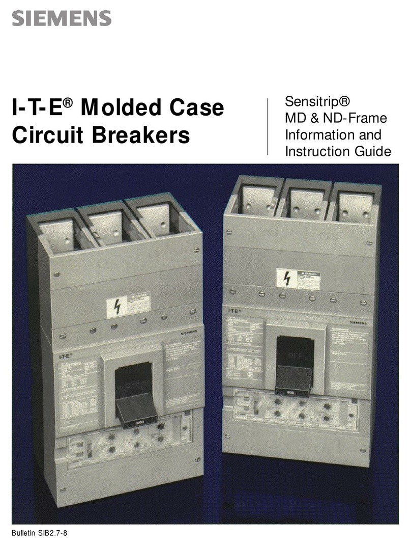
Siemens 8BT2 User manual

Siemens

Siemens 8BT2 User manual

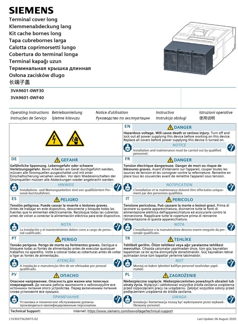
Siemens SENTRON 3WL10 Technical Document

Siemens

Siemens SENTRON 3WL10 Technical Document

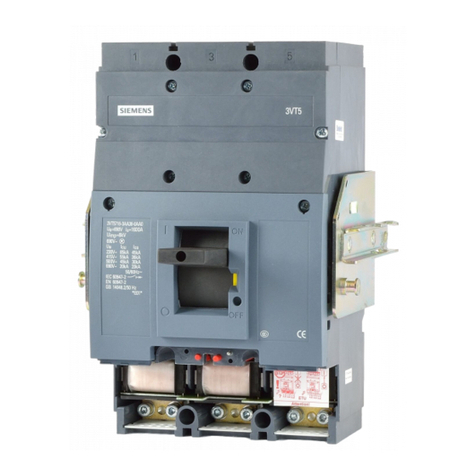
Siemens N2250X User manual

Siemens

Siemens N2250X User manual

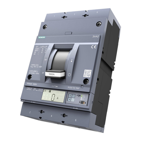
Siemens UL 489 User manual

Siemens

Siemens UL 489 User manual

Siemens SB Series Owner's manual

Siemens

Siemens SB Series Owner's manual

Siemens PCTL83 User manual

Siemens

Siemens PCTL83 User manual

Siemens 3VA51 ED1 Series User manual

Siemens

Siemens 3VA51 ED1 Series User manual

Siemens 3VA9603-0KB03 User manual

Siemens

Siemens 3VA9603-0KB03 User manual

Siemens QF120A Guide

Siemens

Siemens QF120A Guide

Siemens 3WN6 User manual

Siemens

Siemens 3WN6 User manual

Siemens SENTRON 3WL10 User manual

Siemens

Siemens SENTRON 3WL10 User manual

Siemens 3VA2 JP Series User manual

Siemens

Siemens 3VA2 JP Series User manual

Siemens 3VA967 0WA00 Series User manual

Siemens

Siemens 3VA967 0WA00 Series User manual

Siemens VT63 User manual

Siemens

Siemens VT63 User manual

Siemens 5ST303 Series User manual

Siemens

Siemens 5ST303 Series User manual

Siemens SDV-4A User manual

Siemens

Siemens SDV-4A User manual

Siemens 3VA52-EC.1 Series User manual

Siemens

Siemens 3VA52-EC.1 Series User manual

Siemens 3RV1.2 User manual

Siemens

Siemens 3RV1.2 User manual

Siemens 3VF Series Use and care manual

Siemens

Siemens 3VF Series Use and care manual

Siemens 5SP3 Series User manual

Siemens

Siemens 5SP3 Series User manual

Siemens SDV-R User manual

Siemens

Siemens SDV-R User manual

Siemens AFCI Guide

Siemens

Siemens AFCI Guide

Siemens 3WX3623 Series User manual

Siemens

Siemens 3WX3623 Series User manual

Siemens PSR Programming manual

Siemens

Siemens PSR Programming manual

Popular Circuit Breaker manuals by other brands

Acrel ASCB1 Series Installation and operation manual

Acrel

Acrel ASCB1 Series Installation and operation manual

ABB SACE Emax 2 E2.2 manual

ABB

ABB SACE Emax 2 E2.2 manual

Eaton NOVA LBS 15 Installation and operation instructions

Eaton

Eaton NOVA LBS 15 Installation and operation instructions

ABB SACE Emax E1 quick start guide

ABB

ABB SACE Emax E1 quick start guide

WEG FHU ACW125 installation instructions

WEG

WEG FHU ACW125 installation instructions

TERASAKI NHP TemBreak PRO P160 Series installation instructions

TERASAKI

TERASAKI NHP TemBreak PRO P160 Series installation instructions

hager TS 303 User instruction

hager

hager TS 303 User instruction

ETI EFI-4B Instructions for mounting

ETI

ETI EFI-4B Instructions for mounting

Gladiator GCB150 Installation instruction

Gladiator

Gladiator GCB150 Installation instruction

nader NDM3EU-225 operating instructions

nader

nader NDM3EU-225 operating instructions

Eaton 50DHP-VR Instruction handbook

Eaton

Eaton 50DHP-VR Instruction handbook

ABB SACE Emax 2 E6.2 Instruction handbook

ABB

ABB SACE Emax 2 E6.2 Instruction handbook

Gewiss 90 RCD Installation

Gewiss

Gewiss 90 RCD Installation

OEZ LFN Instructions for use

OEZ

OEZ LFN Instructions for use

Eaton Power Defense PDG2 Instruction leaflet

Eaton

Eaton Power Defense PDG2 Instruction leaflet

Bticino L4412CM2 quick start guide

Bticino

Bticino L4412CM2 quick start guide

OEZ 3VA9-RS-4VBH1 Installation, service and maintenance instructions

OEZ

OEZ 3VA9-RS-4VBH1 Installation, service and maintenance instructions

Rockwell Automation Allen-Bradley 140G-G manual

Rockwell Automation

Rockwell Automation Allen-Bradley 140G-G manual

manuals.online logo
manuals.online logoBrands
  • About & Mission
  • Contact us
  • Privacy Policy
  • Terms and Conditions

Copyright 2025 Manuals.Online. All Rights Reserved.

1
3VF 3/4/5/6
Hilfsleitersteckvorrichtung für seitlichen Anbau 3VF 9 624-1VA40
Auxiliary conductor plug-in device for side mounting
Kit de connexion de conducteurs auxiliaires pour montage latéral
Conector de conductores auxiliares para montaje lateral
Connettore ad innesto per conduttori ausiliari per montaggio laterale
Extra anslutningskontakt för sidemontering
Alle Rechte vorbehalten. All rights reserved. Tous droits réservés. Nos reservamos todos los
derechos.
Varning
Drift av elektriska apparater och utrustningar medför att
vissadelaravutrustningenstárunderfarligspänning.
Montering, underhåll, ändringar eller ombyggnader av
effektbrytarefårdärförbarautförasavkvalificeradpersonal
och under iakttagande av gällande säkerhetsföreskrifter.
Säkerställ innan plintarna monteras att alla ledare,
anslutningsdetaljer och plintar är spänningslösa.
Försummelse kan medföra dödsfall, svåra kroppsskador
ellersvåraanläggningsskador.
Avviso di pericolo
Durante il funzionamento, alcune parti dell' apparecchio
elettricositrovanoinevitabilmentesottotensionepericolosa.
Il montaggio, la manutenzione, la sostituzione e
l'equipaggiamentodell'interruttoredevonoessereeseguiti
dapersonalequalificatoosservandolenormedisicurezza.
Prima di effettuare il montaggio dei conettori ad innesto,
assicuarsichetuttiiconduttori,componentid'allaciamento
e morsetti siano privi di tensione.
La non osservanza di tali norme può causare la morte,
gravi lesioni alle persone o ingenti danni materiali.
SvenskaItaliano
Français Español
Advertencia
Cuando se emplean aparatos eléctricos, es inevitable
que piezas de los mismos se encuentren bajo tensiones
peligrosas.
Por tanto,el montaje,elmantenimiento,losmodificaciones
y los complementos con accesorios de los interruptores
depotenciasolamentedebenserefectuadosporpersonal
calificado, tomando en cuenta las medidas de seguridad
correspondientes.
Antes de montar el conector para los conductores
auxiliareses indispensable comprobarque el interruptor
seencuentreenla posición "Desconectado" y que todos
los conductores, piezas de conexión y bornes se
encuentren libres de tensión.
Si esto no se respeta, la consecuencia puede ser muerte,
heridasgravesodañosmaterialesconsiderables.
Attention
Le fonctionnement d'un appareillage électrique implique
nécessairementlaprésencedetensionsdangereusessur
certainesdesesparties.
Le montage, l'entretien, et toutes modifications sur le
disjoncteur doivent être effectués dans le plus grand
respect des règles de sécurité correspondantes.
Avant de procéder au montage du kit de connexion de
concuteursauxiliaires,vérifierquetouslesconducteurs,
tous les éléments de raccordement et toutes les bornes
sont hors tension.
Lanon-applicationdesmesuresdesécuritépeutentraîner
la mort, des lésions corporelles graves ou des dégâts
matérielsimportants.
English
Deutsch
Warnung
Beim Betrieb elektrischer Geräte stehen zwangsläufig be-
stimmte Teile dieser Geräte unter gefährlicher Spannung.
Montage, Wartung, Änderung und Nachrüstung der Lei-
stungsschalter dürfen nur von qualifiziertem Personal
unter Beachtung entsprechender Sicherheitsvorkehrun-
gen durchgeführt werden.
VorMontagederHilfsleitersteckvorrichtungistsicherzu-
stellen, daß sämtliche Leiter, Anschlußteile und Klem-
men spannungsfrei sind.
Bei Nichtbeachtung können Tod, schwere Körperver-
letzungen oder erheblicher Sachschaden die Folge sein.
Warning
Hazardous voltage are present on specific parts in this
electrical device during operation.
Only qualified personnel, paying attention to the relevant
safety precautions, should install, maintain, modify or fit
accessories to the circuit-breakers.
Before mounting auxiliary conductor plug-in device en-
sure that all conductors, connection components and
terminals are in dead state.
Non-observance of this warning can result in death,
severe personal injury or substantial property damage.
Betriebsanleitung/Operating Instructions Bestell-Nr./Order-No.: 3ZX1812-0VF93-8AA0 / 9239 9713 422
2
Suministro Cantidad (uds.)
Placa de montaje 1
Enchufe 1
Tornillo autoterrajante 2
Taptite - M4 x 16
Tornillo autoterrajante 2
Taptite - M4 x 8
Tornillo M4 x 8 2
Description Quantity (Qty)
Mounting plate 1
Plug connector 1
Self-tapping screw 2
Taptite - M4 x 16
Self-tapping screw 2
Taptite - M4 x 8
Screw M4 x 8 2
Lieferinhalt Menge (Stck.)
Montageblech 1
Steckverbinder 1
Schraube Taptite - M4 x 16 2
Schraube Taptite - M4 x 8 2
Schraube M4 x 8 2
Deutsch English
Español
Français
Fourniture Quantité (pièce)
Platine de montage 1
Connecteur 1
Vis auto-taraudeuse 2
Taptite M4 x 16
Vis auto-taraudeuse 2
Taptite M4 x 8
Vis M4 x 8 2
Italiano
Fornitura Quantità (no. pezzi)
Piastra di montaggio 1
Conettore a spina 1
Vite automaschiante 2
Taptite M4 x 16
Vite automaschiante 2
Taptite M4 x 8
Vite M4 x 8 2
Svenska
Leveransens innehåll Kvantitet (Antal)
Montageplåt 1
Kontaktdon 1
Självgägande skruv 2
Taptite M4 x 16
Självgägande skruv 2
Taptite M4 x 8
Skruv M4 x 8 2
3
EnglishDeutsch
1a)Bei 3VF3 2 Modulbefestigungsschrauben (2) entfernen
undMontageblech(1)mitselbstschneidendenSchrauben
(2a) Taptite - M4 x 16 an Modul (3) befestigen.
1b)Bei 3VF4/5/6 Montageblech (1) mit selbstschneidenden
Schrauben (2b) Taptite - M4 x 8 auf Grundplatte (4) befe-
stigen.
2) Steckverbinder (5) nach Verdrahtungsplan verdrahten.
(Für inneres und äußeres Zubehör ist je ein Steckverbin-
dererforderlich.BeiBedarfisteinzusätzlicherSteckverbin-
der gesondert mit MLFB 3VF9624-1VJ40 zu bestellen.)
3) Steckverbinder (5) mit Schrauben (6) M4 x 8 an Montage-
blech (1) montieren.
1a)Onmounting3VF3remove2modulefixingscrews(2)and
fasten mounting plate (1) with self-tapping screws (2a)
(Taptite - M4 x 16) to module (3).
1b)On 3 VF4/5/6 fasten mounting plate (1) with self-tapping
screws (2b) (Taptite-M4 x 8) to baseplate (4).
2) Wire up plug connector (5) according to diagram.
(Two plug connectors, i.e. one for internal and external
accessories respectively, are required. If necessary, an
additional plug connector must be ordered separately
under machine readable product designation 3VF9624-
1VJ40).
3) Mount plug connector (5) with M4 x 8 screws (6) to plate
(1).
Français Español
1a)Surle 3VF3, défaire 2vis de fixationde module (2)et fixer
laplatinedemontage(1)sur lemodule(3)pardevis auto-
taradeuses (2a) Taptite - M4 x 16
1b)Sur les 3VF4/5/6, fixer la platine de montage (1) sur la
plaque de base (4) par des vis auto-taradeuses (2b)
Taptite - M4 x 8.
2) Câbler le connecteur (5) conformément au schéma de
branchement.
(Il faut un connecteur par les accessoires internes et un
autre pour les accessoires externes). Au besoin, on peut
commander un connecteur supplémentaire sous la
référence 3VF9624-1-VJ40.)
3) Fixer le connecteur (5) à la platine de montage (1) au
moyen des vis M4 x 8 (6).
1a)En 3VF3 quitar los 2 tornillos de sujeción del módulo (2) y
fijarlaplacademontaje(1)conlostornillosautoterrajantes
(2a) Taptite - M4 x 16 al módulo (3).
1b)En 3VF4/5/6 fijar la placa de montaje (1) con los tornillos
autoterrajantes(2b)Taptite-M4x8alaplacadebase(4).
2) Establecer las conexiones del enchufe (5) según el
esquema de cableado.
(Se necesita un conector para los accesorios internos y
otroparalosexternos.Encasonecesariohayquepedirun
conector suplementario con MLFB 3VF9624-1VJ40.)
3) Montar el conector (5) con los tornillos (6) M4 x 8 en la
placa de montaje (1).
SvenskaItaliano
1a)3VF3:togliereleduevitidifissagiodelmodulo(2)efissare
la piastra di montaggio (1) al modulo (3) mediante viti
automaschianti Taptite M4 x 16.
1b)3VF4/5/6: fissare la piastra di montaggio (1) sulla piastra
base (4) mediante viti automaschianti Taptite M4 x 8 (2b).
2) Cablareil connettore (5)secondo lo schemadi cablaggio.
(Pergliaccessoriinternieperquelliesternisononecessari
due conettori separati. In caso di necessità ordinare un
connettoreaspinasupplementareindicandoilno.d'ordinaz.:
3VF9624-1VJ40.)
3) Montare il connettore (5) sulla piastra di montaggio (1)
mediante viti M4 x 8.
1a)3VF3:Tagbort2modulfästskruvarochmontageplåten(1)
med självgängande skruvar (2a) Taptite - M4 x 16 på
modulen (3).
1b)3VF4/5/6: Fäst montageplåten (1) med självgängande
skruvar (2b) Taptite - M4 x 8 på bottenplattan (4).
2) Anslut ledningarna enligt ledningsdragningsschema till
kontaktdonet (5).
(Ettkontaktdonbehövsförvarderainvändigaochutvändiga
tillbehör. Vid behov skall ett extra kontaktdon beställas
särskilt tillsammans med MLFB 3VF9624-1VJ40.
3) Fästkontaktdonet (5) til monteringsplåten (1) medskruvar
(5) M4 x 8.
5
3
6
2
2a
1
3VF3
4
2b
65
1
3VF4/5/6
4
Siemens Aktiengesellschaft Bestell-Nr./Order No.: 3ZX1812-0VF93-8AA0 / 9239 9713 422
Bestell-Ort/Place of Order: A&D CD SE PC Log M Berlin
Printed in the Federal Republic of Germany
AG 11.97 Kb De-En-Fr-Sp-It-Sv
Verdrahtungsplan/Wiringdiagram/Schémadebranchement/Esquemadecableado/Schemadicablagio/Ledningsdragningsplan
Steckvebinder I/Plug connector I/Connecteur I/Enchufe I/Conettore ad innesto I/Kontaktdon I
a1 a3 a6 b2 b5
a2
a1
a2 a4 a5 a7 b1 b3 b4 b6 b7
SL
F3F2S1S3
C1
C2
D1
D2
11 21 15 25
12 14 22 24 16 18 26 28
Steckverbinder II/Plug connector II/Connecteur II/
Enchufe II/Conettore ad innesto II/Kontaktdon II
a6 a4 a1 a1 b1 b3 b5 7a
a5 a3 a2 a2 a3 b2 b4 b6 b7
M
116 115 111 1
113 112 114 2 3
L1
N
S4SL
77
67
78
68
➀➁➂
Inneres Zubehör/
Internal accessories/
Accessoiresinternes/
Acesorios internos/
Accessori interni/
Invändiga tillbehör
Äußeres Zubehör/
Externalaccessories/
Accessoiresexternes/
Acesorios externos/
Accessori esterni/
Utvändiga tillbehör
Deutsch
➀Motorantrieb
➁Magnetantrieb
➂Elektr. Auslöser
English
➀Motor operating mechanism
➁Solenoidoperatingmechanism
➂Electrical release
Français Español
➀Commande à moteur
➁Commande à électroaimant
➂Déclencheur électr.
➀Accionamiento por motor
➁Accionamiento magnético
➂Disparador eléctrico
Italiano Svenska
➀Azionamento motorizzato
➁Azionamento a solenoide
➂Sganciatore electtronico
➀Motordrivning
➁Magnetdrivning
➂Elektr. utlösare
(f) (r) a b
C1D124
F3C2F2D215 S1
11 16
12 18 S3
14 25
S121 26
22 28
Steckverbinder I/Plug connector I/Connecteur I/
Enchufe I/Conettore ad innesto I/Kontaktdon I
SteckverbinderII/Plug connectorII/ConnecteurII/
Enchufe II/Conettore ad innesto II/Kontaktdon II
1
2
3
4
5
6
7
(HS)
(AS)
ab
1 111 L1
2 114 N
3 112 67
115 68 S4
113 77
116 78
SL
1
2
3
4
5
6
7
➀
➁
Steckerbelegung für Steuerleitungssteckvorrichtung/Pin assignment for control cable connector/
Brochageduconnecteurpourcircuitsauxiliaires/Asignacióndepinesenconectordelcabledecontrol/
Assegnazione dei pin dei conettori per i cavi di comando/Stiftlayout för manöverledningsanslutning
(HS)
Herausgegeben von
Bereich Automations- und Antriebstechnik
Niederspannungs-Schalttechnik
Schaltwerk Berlin
D - 13623 Berlin
Änderungen vorbehalten
Published by the
Automation & Drives Group
Control and Distribution
Schaltwerk Berlin
D - 13623 Berlin
FederalRepublicofGermany
Subject to change