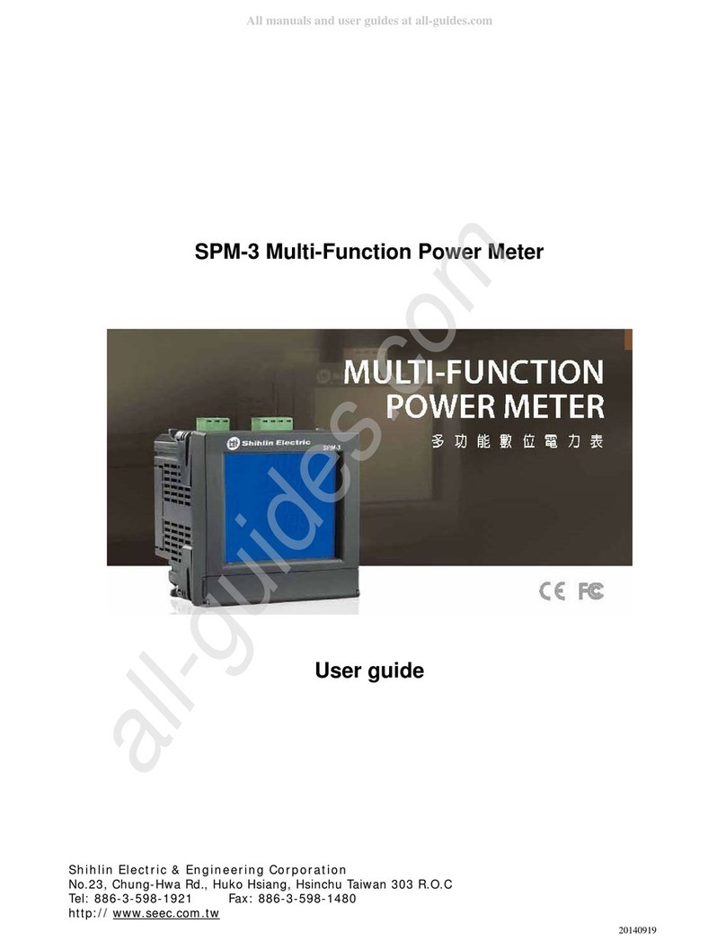
Shihlin electric SPM-3 User manual

SPM-3 Multi-Function Power Meter
User guide
20100831
www.biall.com.pl

Shihlin Electric SPM-3 User Guide
1
Content
Chapter 1 Introduction
1.1 Product Introduction
1.2 Caution
1.2.1 Danger
1.2.2 PRODUCT WARRANTY & CUSTOMER SUPPORT
1.2.3 LIMITATION OF WARRANTY
1.3 Specification
Chapter 2 Installation
2.1 Safety
2.2 Mounting
2.2.1 Size and Latch
Chapter 3 Connection
3.1 Back view of connect port
3.1.1 Aux. Power Supply
3.1.2 Digital Output
3.1.3 Current Terminal
3.1.4 Voltage Terminal
3.2 Wiring diagram
3.2.1 1P2W/1CT
3.2.2 1P3W/2CT
3.2.3 3P3W/2CT
3.2.4 3P3W/3CT
3.2.5 3P4W/3CT
Chapter 4 Display and setup
4.1 Display
4.2 Operation
4.2.1「M」Button
4.2.2 「P」Button
4.2.3「E/T」Button
4.2.4 「V/A」button
4.3 Setting「M」、「P」、「E/T」and「V/A」
4.3.1 General Setting (N)
4.3.2 Clear Setting (C)
4.3.3 Alarm Setting (A)
Chapter 5 Communication format
5.1 RS485
5.1.1 RS485 standard
5.1.2 Wiring for instruments communication
5.2 Modbus
5.2.1 Modbus Format
5.3 Communication protocol
5.4 IEEE 754 Format
5.5 Modbus RTU Mode
5.6 Modbus Function Code
5.7 SPM-3 Parameter
www.biall.com.pl

Shihlin Electric SPM-3 User Guide
2
Chapter 1 Product Introduction
1.1 SPM-3 Introduction
SPM-3 is designed for single and three phase power monitoring and measurement. It provides wide
rang of measurements including current, voltage, energy, watt, power factor, watt-hour,
frequency…etc.
Product Features:
Comply IEC62053-22 Class 0.5 standard
V、I accuracy <0.2%, Wh<0.5%, with bi-directional energy measurement
More than 90 parameters measure
Current direction setting to correct the display value
Large size of LCD with backlight adjustment in 4-stage, easy to operate
Power Quality measurement in V/I unbalance、V Eligibility、Min.& Max.parameters
Compact size, standard DIN 96*96, equipped with four clips to tight the meter on the sheet metal
With RS485 communication protocol
1.2 Caution
1.2.1 Danger
The meter contains hazardous voltages. The meter should never be disassembled. Failure to observe
this practice can result in serious injury or death. Any work on or near energized meters, meter sockets,
or other metering equipment can present a danger of electrical shock. It is strongly recommended that
all work should be performed only by qualified industrial electricians and metering specialist. Arch
Meter Corporation assumes no responsibility if your electrical installer does not follow the appropriate
national and local electrical codes.
1.2.2 PRODUCT WARRANTY & CUSTOMER SUPPORT
Arch Meter Corporation warrants all products free from defects in material and workmanship for a
period of one year from the date of shipping. During the warranty period, we will, at our position, either
repair any product that proves to be defective. To report any defect, please contact :
+886-3-5631359 or sales@archmeter.com.
Please have the model, serial number and a detailed problem description available when you call. If the
problem concerns a particular reading, please have all meter readings available. When returning any
merchandise to Arch Meter Corporation a return SN. is required.
1.2.3 LIMITATION OF WARRANTY
This warranty does not apply to defects resulting from unauthorized modification, misuse, or use for
reason other than electrical power monitoring. The supplied meter is not a user-serviceable product.
www.biall.com.pl

Shihlin Electric SPM-3 User Guide
3
1.3 Product Spec.
Aux Power AC80-264V/DC100-300V, Max.2.3W
Input Voltage CATII 10V-600V L-L*
Input Current 2mA-5A
Accuracy V、I 0.2%,W 0.5% (PF=1.0)
Frequency 45-65Hz
Measures V, I, kW, kvar, kVA, kWh, kvarh, kVAh
PF, Frequency, Demand,
Running hour
Alarms NONE、OVER V/I、OVER F;UNDER V /I、UNDER F;OVER Dmd;
ANY
Power Quality V/I unbalance、V Eligibility、Min.& Max.parameters
Display Mono 68X59 LCD
Communication RS485*1, LonTalk(option)
Timer RTC
Wiring Ports Aux Power、Voltage、Current、DO*2、RS485、LON
I/O DO OUTPUT*2;DO1 Alarm output、DO2 Pulse/ Alarm output
Operation
Temperature -20℃-70℃
Storage
Temperature -25℃-80℃
Humidity 20-90%RH
Dust/Water
Proof Rating Panel:IP52,Case:IP20
Size 96(W) × 96(H) × 97(L) mm
Power
consumption 0.45~0.7W (Backlight off)
1.3~1.7W (Max. ,Backlight)
2.3W (Max. Backlight & Lon module)
Environmental
Conditions Indoor use
Altitude up to 2000M
Transient overvoltage on the mains supply is 2500V
Pollution degree:2
*CATII-Is for measurement performed on circuits directly connected to the low voltage installation
www.biall.com.pl

Shihlin Electric SPM-3 User Guide
4
Chapter 2 Installation
2.1 Safety
On receipt of the instrument and prior to installation, makes sure it has not been damaged during
shipment.
The instrument is no longer safe when,
a) Shows clear signs of damage
b) Does not work
c) Long storage under extreme conditions
d) Damage during shipment
2.2 Mounting
This instrument should install on vibration free switchboard and with environment temperature
between -20℃~70℃, humility between 20-90%RH(no condensing)
For the instrument is already equipped with an internal protection fuse, a 1AmAT HBC fuse is still
recommended during installation
Prior to maintain/repair this instrument, always disconnect this instrument from all power sources
Only have qualified and authorized personnel to carry out installation, maintenance and repair
Water proof for front panel IP52, case IP20
2.2.1 Size and Latch
Front View(mm) Back View (mm)
Side View(mm)
After mounting the instrument, place all four support latch in position.
Panel cut-out area is 91.5x91.5mm (+/-0.5mm)
www.biall.com.pl

Shihlin Electric SPM-3 User Guide
5
Chapter 3 Connection
3.1 Back view of connect port
1.Aux Power(N-, ,L+)
2.Digital output (Com2 DO2 Com1 DO1)
3.Current Terminal (3L 3S 2L 2S 1L 1S)
4.Lon Port(D-,D+)
5.Voltage Terminal (N,C,B,A)
6.RS485 Port (D-,COM,D+)
3.1.1 Aux. Power Supply
Before powering the instrument, verify the pin position at L and N, leave the middle pin blank.
Power standard is 80-264Vac/100-300Vdc.
An internal protection fuse 250V, 1A is equipped.
The instrument Aux. power must not be earthed.
3.1.2 Digital Output
2 channel 4 pin digital output (Com2 DO2 Com1 DO1)
12-240VAC-DC/120mA max
Com1 DO1 for digital output1, Com2 DO2 for digital output 2
Port 1 assign selection : NONE、OVER V/I、OVER F;UNDER V /I、UNDER F;OVER Dmd;ANY。
Port 2 assign selection : Energy pulse output base on kh(wh/ pulse) setting or alarm output same
as port 1
3.1.3 Current Terminal
The current input are 3 channels/6 terminals(3L 3S 2L 2S 1L 1S)
Input current range from 2mA to 5A (CT secondary)
Warning !
The CT input current must not exceed 10A
Warning !
Be sure to short secondary’s of each current transformer, before removing the CT connection inputs.
2
3
5
4
6
1
www.biall.com.pl

Shihlin Electric SPM-3 User Guide
6
3.1.4 Voltage Terminal
There are 4 voltage terminals (N.C.B.A) 。
The instrument measure voltage from 10V-600V RMS.(PT secondary)
Voltage must not exceed 600V, in case of over 600V, voltage transformer need to be applied.
Note !
3P3W/2CT and 3P3W/3CT wiring, only connect “C A N”, and leave “B” blank
www.biall.com.pl

Shihlin Electric SPM-3 User Guide
7
3.2 Wiring diagram
3.2.1 1P2W/1CT
3.2.2 1P3W/2CT
3.2.3 3P3W/2CT
3.2.4 3P3W/3CT
www.biall.com.pl

Shihlin Electric SPM-3 User Guide
8
3.2.5 3P4W/3CT
www.biall.com.pl

Shihlin Electric SPM-3 User Guide
9
Chapter 4 Operation & Setting
4.1 Display
The SPM-3 is equipped with a large back-lit LCD and 4 function buttons. It shows up to five
measurements simultaneously.
Item Display Content
1 Values, for V,I,KW……Demand, eligibility rate and unbalance rate
2 Values, for energy & time
3 Load percentages
4 Unbalance rate indicator
5 Types of measurement (I,U,E,P….)
6 Alarm buzzer on/off
7 Indicator for time display in zone 2
8 Indicator for energy display in zone 2
9 Indicator for pulse output and communication
10 Display for power factor and load characteristics
11 Units for measurements
12 Function Buttons, “M” “P” “E/T” “V/A”
13 DO1, DO2 Status
***THD、DI、DO3、DO4:To be available in near future
1
3
4
5
6
7
8
9
10
2
11
12
13
www.biall.com.pl

Shihlin Electric SPM-3 User Guide
10
4.2 Operation
The SPM-3 equipped with function buttons to easily view all values and modify device setting. From left
to right, there are「M」、「P」、「E/T」and「V/A」respectively.
Button「M」to display maximum and minimum values
Button「P」to display power for each phase and total , power factor (PF), frequency (F) and power
demand.
Button「E/T」to display Energy、RTC and running hour
Button「V/A」to display Voltage and Current
4.2.1「M」Button
Press successively to present the maximum minimum and average values of present measure
parameters. For example, if SPM-3 is currently display “Voltage” with “U” shown on the left middle of
the screen, press “M” Button will show the Max./Min. and average values of Voltages. The following lists
all the values that can be shown for Max./Min. and average values depending on the display parameters
which are showing now
Max./Min. Voltage(L-L,L-N,Average)
Max./Min. Current(Per phase,Average)
Max./Min. Voltage & Current unbalance rate
Max./Min. kW(Per phase,Total)
Max./Min. kvar (Per phase,Total)
Max./Min. kVA (Per phase,Total)
Max./Min. kW-t, kVA-t, kvar-t
Min. PF
Max./Min. Frequency
Max. Power Demand
4.2.2 「P」Button
「P」Button is for power selection. Press「P」Button successively to obtain:
Active power (P) per phase and total
Reactive power (Q) per phase and total
Apparent power (S) per phase and total
Total active power (P), reactive power (Q) , apparent power (S) and power factor(PF)
Total active power (P), reactive power (Q) , apparent power (S) and frequency(F)
Previous power demand kW, , demand subinterval remain time (sec) and current power demand
kW
4.2.3「E/T」Button
「E/T」Button is for Energy & Time. Press「E/T」successively to obtain the following values in the zone
8 (bottom lane of the screen)
Total active energy (kWh-t)
Total reactive energy (kvarh-t)
Total apprerant energy (kVAh-t)
Total meter running hours (Total)
Total meter running hours with load (Net)
Year-Month-Day
Hr-Min-Sec.
4.2.4 「V/A」button
「V/A」button is for showing the Voltage and Current. Press button successively to obtain
Phase to phase voltages and average (U)
Phase to neutral voltages and average (U)
Instantaneous current (I)
Unbalance rate for voltages and current
Voltage eligibility rate
「V/A」button then「M」button
「P」button then「M」button
www.biall.com.pl

Shihlin Electric SPM-3 User Guide
11
4.3 Setting「M」、「P」、「E/T」and「V/A」
To enter setting mode, press「M」and 「V/A」buttons simultaneously. The setting mode is used for:
basic operation, clear informal data and alarms setting
「M」to move cursor right ward like「」
「P」to move the cursor down ward like「」or 「reduce one」
「E/T」to move the cursor up ward like「」or 「add one」
「V/A」to confirm the selection like「Enter」, and turn to next page
「M」and「V/A」together to move back like「ESC」or back to operation display
First, to press「M」a「V/A」simultaneously to enter password entering page, it required 4 digits (default
is 0000).
PASS
WORD
0000
Then, select the setting from「BASIC」、「ALARM+I/O」、「CLEAR」by used「P」or「E/T」
P0
MAIN
MENU
BASIC / ALARM+I/O / CLEAR
4.3.1 General Setting (N)
N1: Address Setting from 1-255 (Default 15)
N1
Add
015
N2: BAUD RATE Setting - 4800, 9600, 19200, 38400, 57600. (Default 19200)
N2
BAUD
RATE
19200
N3: STOP BIT Setting - “1” or “2” (Default 1)
N3
STOP
BIT
1
N4: Wire Type Setting -1P2W,1P3W,3P3W-2CT,3P3W-3CT,3P4W-Y,AUTO (Default AUTO)
N4
WIRE
TYPE
3P4W
N5: PT Primary Setting from 60-600000 (Default 110)
N5
PT1
000110
N6: PT2 Secondary Setting from 1-600 (Default 110)
N6
PT2
110
www.biall.com.pl

Shihlin Electric SPM-3 User Guide
12
N7: CT Primary Setting from 1-500 (Default 1)
N7
CT1
000
1
N8: CT Secondary Setting from 1-5 (Default 1)
N8
CT2
1
N9: BACK LIGHT TIME OUT Setting from 0-120 minutes (Default 1) .
If 0 is chosen, the back light will be always ON. Enter any key to turn on back light.
N9
BACK
LIT
120
N10: BACK LIGHT LEVEL Setting from 0-4 (Default 3) .
If 0 is chosen, the back light will be always OFF.
N10
BACK
LIT
LVL
3
N11: I-1 Current Direction Setting - “Positive” or “Negative”. (Default POSITIVE).
If the current is connected in wrong direction, select “Negative” to correct the display
value.
N11
I-1
POSITIV E
N12: I-2 Current Direction setting - “Positive” or “Negative”. (Default POSITIVE).
If the current is connected in wrong direction, select “Negative” to correct the display
value.
N12
I-2
POSITIVE
N13: I-3 Current Direction setting - “Positive” or “Negative”. (Default POSITIVE).
If the current is connected in wrong direction, select “Negative” to correct the display
value.
N13
I-3
POSITIVE
N14: V1(V12) Voltage Eligibility Rate Up Limit Setting from 0-65535 (Scale 0.1, refer to
Secondary) (Default 65535)
N14
U1
UP
LMT
65535
N15: V1(V12) Voltage Eligibility Rate Low Limit Setting from 0-65535 (Scale 0.1, refer to
Secondary) (Default 0)
N15
U1
LOW
www.biall.com.pl

Shihlin Electric SPM-3 User Guide
13
LMT
00000
N16: V2(V23) Voltage Eligibility Rate Up Limit Setting from 0-65535 (Scale 0.1, refer to
Secondary) (Default 65535)
N16
U2
UP
LMT
65535
N17: V2 (V23) Voltage Eligibility Rate Low Limit Setting from 0-65535 (Scale 0.1, refer to
Secondary) (Default 0)
N17
U2
LOW
LMT
00000
N18: V3 (V31) Voltage Eligibility Rate Up Limit Setting from 0-65535 (Scale 0.1, refer to
Secondary) (Default 65535)
N18
U3
UP
LMT
65535
N19: V3 (V31) Voltage Eligibility Rate Low Limit Setting from 0-65535 (Scale 0.1, refer to
Secondary) (Default 0)
N19
U3
LOW
LMT
00000
N20: Demand Mode Setting -「BLOCK」or「ROLLING」(Default BLOCK)
N20
DMD
MODE
BLOCK
N21: Sub-Interval Number Setting - 1,2,3,4,5,6,10, only used for “Rolling Mode”
(Default 1)
N21
SUB
INTV
NUM
1
N22: Sub-Interval Length (Time) Setting - 1,2,3,4,5,6,10,12,15,30,60 min. (Default 15)
N22
SUB
INTV
LENG
15
N23: Date Setting
N23
DATE
2009.02.20
www.biall.com.pl

Shihlin Electric SPM-3 User Guide
14
N24: Time Setting
N24
TIME
00:00:00
N25: Password Setting-four digits from 0000-FFFF (Default 0000)
N25
PASS
WORD
0000
4.3.2 Clear Setting (C)
C1: Energy Reset – Yes or No
C1
ENRG
RST
NO
C2: Reset All – Yes or No
C2
RST
ALL
NO
C3: Reset OF Total Meter Run Hour – Yes or No
C3
RST
R-HR
TOT
NO
C4: Reset OF Net Load Run Hour – Yes or No
C4
RST
R-HR
NET
NO
C5: Demand Reset – Yes or No
C5
RST
DMD
NO
C6: Reset of Max and Min values – Yes or No
C6
RST
MAX
MIN
NO
C7: Reset to Default - Yes or No
C7
RST
DEFT
NO
www.biall.com.pl

Shihlin Electric SPM-3 User Guide
15
C8: Reset Voltage Eligibility Rate – Yes or No
C8
RST
VER
NO
4.3.3 Alarm Setting (A)
A1: Enable Alarm – On or Off (Default OFF)
A1
ALRM
OFF
A2: Enable Buzzer – On or Off (Default OFF)
A2
BUZZ
OFF
A3: DO1 can be assigned as the alarm output, and can be selected from「None」、「Any」、「Over
V」、「Over I」、「Over F」、「Over Dmd」、「Over V」、「Under I」、「Under F」(Default None)
A3
DO1
ALRM
NONE
A4: DO2 can be assigned to output「PULSE」or「ALARM」(Default PULSE)
A4
DO2
OUT
PUT
PULSE /ALARM
A5: If DO2 is assigned to「ALARM」, then select from 「None」、「Any」、「Over V」、「Over I」、
「Over F」、「Over Dmd」、「Over V」、「Under I」、「Under F」(Default None)
A5
DO2
ALRM
NONE
A6: If DO2 is assigned to「PULSE」, then select from「NONE」、「kWh」、「kvarh」、「kVAh」(Default
NONE)
A6
PULS
OUT
PUT
NONE
A7: If DO2 is assigned to「PULSE」, pulse rate can be 1 to 100, 1 stand for 1 wh/pulse
(Default 1)
A7
kh
0001
A8: Over Voltage Alarm – 「ENABLE」or 「DISABLE」(Default DISABLE)
A8
OVER
V
DISABLE
www.biall.com.pl

Shihlin Electric SPM-3 User Guide
16
A9: Over Current Alarm –「ENABLE」or 「DISABLE」(Default DISABLE)
A9
OVER
I
DISABLE
A10: Over Frequency Alarm –「ENABLE」or 「DISABLE」(Default DISABLE)
A10
OVER
FREQ
DISABLE
A11: Over Demand Alarm –「ENABLE」or 「DISABLE」(Default DISABLE)
A11
OVER
DMD
DISABLE
A12: Under Voltage Alarm –「ENABLE」or 「DISABLE」(Default DISABLE)
A12
UNDE
V
DISABLE
A13: Under Current Alarm –「ENABLE」or 「DISABLE」(Default DISABLE)
A13
UNDE
I
DISABLE
A14: Under Frequency Alarm –「ENABLE」or 「DISABLE」(Default DISABLE)
A14
UNDE
FREQ
DISABLE
A15: Over Voltage Alarm Setting from 0-600000 (Default 600000)
A15
OVER
V
SET
600000
A16: Over Voltage Alarm Condition Clear Setting from 0-600000 (Default 0)
A16
OVER
V
CLR
0000000
A17: Over Current Alarm Setting from 0-9999 (Default 9999)
A17
OVER
I
SET
9999
www.biall.com.pl

Shihlin Electric SPM-3 User Guide
17
A18: Over Current Alarm Condition Clear Setting from 0-9999 (Default 0)
A18
OVER
I
CLR
0000
A19: Over Frequency Alarm Setting from 45-65 (Default 65)
A19
OVER
FREQ
SET
63
A20: Over Frequency Alarm Condition Clear Setting from 45-65 (Default 45)
A20
OVER
FREQ
CLR
43
A21: Over Demand Alarm Setting from 0-65535 kW (Default 65535)
A21
OVER
DMD
SET
65535
A22: Over Demand Alarm Condition Clear Setting from 0-65535 kW (Default 0)
A22
OVER
DMD
CLR
00000
A23: Under Voltage Alarm Setting from 0-600000 (Default 0)
A23
UNDE
V
SET
000000
A24: Under Voltage Alarm Condition Clear Setting from 0-600000 (Default 600000)
A24
UNDE
V
CLR
600000
A25: Under Current Alarm Setting from 0-9999 (Default 0)
A25
UNDE
I
SET
0000
A26: Under Current Alarm Condition Clear Setting from 0-9999 (Default 9999)
A26
UNDE
I
CLR
9999
www.biall.com.pl

Shihlin Electric SPM-3 User Guide
18
A27: Under Frequency Alarm Setting from 45-65 (Default 45)
A27
UNDE
FREQ
SET
45
A28: Under Frequency Alarm Condition Clear Setting from 45-65 (Default 65)
A28
UNDE
FREQ
CLR
65
www.biall.com.pl

Shihlin Electric SPM-3 User Guide
19
Chapter 5 Communication
5.1 RS485
5.1.1 RS485 standard
PARAMETERS
Mode of Operation Differential
Number of Drivers and Receives 32 Drivers / 32 Receivers
Maximum cable length( meters) 1200
Maximum data rate ( baud ) 10M
Maximum common mode voltage ( Volts ) 12 to -7
Maximum Driver Output Levels ( Loaded ) +/- 1.5
Maximum Driver Output Levels ( Unloaded ) +/- 6
Drive Load ( Ohms) 60( min )
Driver Output short circuit Resistance ( kohms) 150 to Gnd, 250 to -7 or 12V
Minimum receiver input Resistance ( kohms) 12
Receiver sensitivity +/- 200mv
5.1.2 Wiring for instruments communication
RS485communication must used twisted paired wire, as show in the following program. “D+” connect
to one wire and “D-” to the other one
Cautions :
There must be no more than two wires connected to each terminal, this ensures that
a “Daisy Chain” or “Straight Line” configuration is used. A “star” or a network with
“Stubs(Tees)” is not recommended as reflections within the cable may result in data
corru
p
tion。
Master
D- D+ D- D+ D- D+ D- D+
120 ohm 120 ohm
Slave Slave Slave
www.biall.com.pl
Other manuals for SPM-3
2
Table of contents
Other Shihlin electric Measuring Instrument manuals
