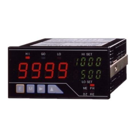
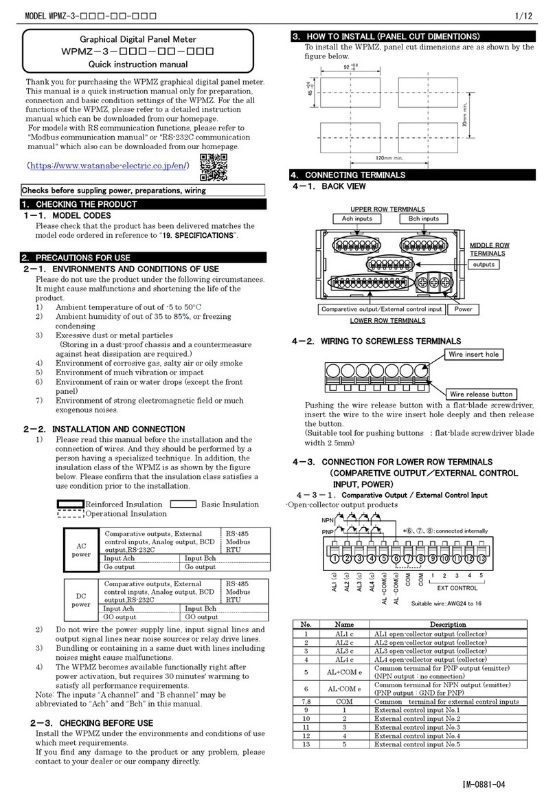
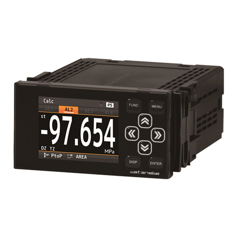
WATANABE A9000 Series User manual

Instruction Manual for MODEL A9□11-0□,A9□12-0□1/8
(1) Applying a voltage or current exceeding its maximum permissible value may cause the
unit to be damaged.
(2) Always use the unit within the specified voltage range: otherwise, it may cause a fire,
electric shock or personal/equipment damage.
(3) For the purpose of functional improvement, the information written herein may be
changed without prior notice.
(4) Information contained herein is considered accurate to the best of our knowledge.
If you have any question or comment on the information, please contact us or our
distributor.
(5) Read this manual carefully and thoroughly before starting to operate the unit,
and keep the manual available for future reference.
1. Before Using the Unit
Thank you for purchasing our A9000 Series Digital Panelmeter. Please
make sure that the operator who uses the panelmeter keeps the manual
on hand. Also, the meter should be checked upon receipt for damage
that might have occurred while in transit. Should the product be
damaged or any accessory be missing, notify your sales representative
or our sales office directly.
1.1. Model and Suffix Code Configuration
The model and suffix code of the A9000 series are as shown below.
Check that the product received matches the one you selected when
ordering.
1.2. Checking the Accessories
The A9000 series accessories include one copy of this instruction
manual, one unit label and a connector for BCD outputs / external
control inputs.
2. Mounting Method
2.1. Panel Cutout Size
Panel cutout size for mounting the A9000 series digital panelmeter is as
shown below:
2.2 External Dimensions
2.3 How to Mount the Unit on the Panel
(1) Do not install the unit where it is exposed to dust, particles, chemicals harmful to
electric components, corrosive gases, etc.
(2) When this unit is installed inside other equipment, pay attention to the heat radiation
and keep the heat inside the equipment 50°C or below.
(3) Exercise care so that the product is not subject to vibrations or shocks.
3. Terminals and Connections
①:Input terminal HI (+ input terminal of 11 or 12, 22 or 23 -range )
②:Input terminal HI (+ input terminal of 13 or 14, 24 or 25 -range )
③:Input terminal LO (- input terminal )
* Selecting input range can not be done only by connecting input signal
to a suitable terminal. Please set the RANG parameter in condition data.
See “4.6.(8) Setting condition data”.
* Make input signal wires as short as possible and keep them away from
other signal wires.
* Use two-core shielded cables in locations with a lot of external noise
and connect the external sheaths to the LO side of the signal source at
one point.
* If harmonic noise is superimposed on an input signal, insert a low-pass
filter in the input. However, care must be exercised depending on the
usage conditions because a delay in response time is caused in time
constant.
④⑤⑥:NC terminals
*Do not connect anything to the NC terminals.
⑦:Power terminal (In case of DC POWER : 0 V)
⑧:Power terminal (In case of DC POWER : +V)
*This panelmeter has no power switch. Connecting it to a power source
causes it to be operable immediately.
①
②
③
④
⑤
⑥
⑦
⑧
suitable solder less terminals
5.8mm or less
5.8mm or less
Lower Terminals
Instruction Manual for A9000 Series
Digital Panelmeter
A9□12-0□ for DC Current measurement
A9□11-0□ for DC Voltage measurement
(1)After removing the mounting bands, insert
the main unit into a opening in a panel from
the front side of the panel.
(2)Attach the mounting bands to main unit
from the rear side of the panel for fixing.
Panel (front side)
Panel (rear side)
mounting band
53
66.5
8.9
7.8
8.7
96
91.5
48
53
56.5
8.9
Power input terminals
Signal input terminals
BCD output / External control input connector
2015.12
UX-34076k
CAUTION
*Recommended panel thickness:
0.8 to 5 mm
(Unit: mm)
+
0
.
8
92
MIN 120
MIN 70
-
0
45
+0.6
-0
CAUTION
*Every model is provided with external control inputs.
1
DC current
Comparative
5
B
D
F
AC current (true RMS)
Precess signal
Temparature sensor
AC large current (true RMS)
4
12-24V DC
DC voltage
AC voltage (true RMS)
1
2
AC large voltage(15range, true RMS)
E
C
6
Temparature sensor
DC large voltage(15range)
(thermocouple sensor)
(resistance tempararure detector)
100-240V AC
Power
Input :
Display :
5-12V DC
4
Single
1
3
supply :
3
0
BCD(Open collector)+external control inputs
Output :
output :
2
(None)+external control inputs
(None)
1
BCD (TTL)+external control inputs
□
9
0
□
A
□
1
-
WATANABE ELECTRIC INDUSTRY CO., LTD.

Instruction Manual for MODEL A9□11-0□,A9□12-0□2/8
Upper terminals (without BCD outputs)
Upper terminals(with BCD outputs)
Upper Connector : HIF-3BA-34PA-2.54DS
(HIROSE)
Attachment Upper Connector : HIF-3BA-34D-2.54R
(HIROSE)
1 to 17:Outputs of bits 1,2,4 and 8 of each digit
18:BCD polarity output
19:BCD overrange output
20:BCD PC (print control) output
21:BCD enable input
・Connecting this terminal to COM terminal or bringing the potential of
this terminal to “0” level causes BCD outputs to be high impedance
or transistors to be turned off.
* In the case of “without BCD output” option, terminals 1 to 21 are no
connection.
22,30,33,34:NC
・Do not connect anything to the NC terminals.
23-26:COM
・Common terminals for BCD outputs and control terminals.
27:Hold input
・By shorting this terminal to COM terminal or bringing its potential to
the “0” level, the panelmeter maintains its indication.
28:Peak hold input
・By shorting this terminal to COM terminal or bringing its potential to
the “0” level, the panelmeter displays maximum value (Peak hold),
minimum value (Valley hold) or the difference value between the
maximum value and the minimum value (Peak-Valley hold). These
functions can be switched by using condition data.
29:Digital Zero input
・By shorting this terminal to COM terminal or bringing its potential to
the “0” level, the panelmeter performs measurements with the latest
displayed value as zero and displays the width of variations from that
point onward.
31,32: Pattern select inputs
・By combining states of P.SEL0 and P.SEL1 terminals (connecting or
not to the COM terminal / bringing its potential to the “0” level or the
“1” level), the panelmeter uses one of the 4 patterns of scaling data
set by scaling data setting.
*”0” level:0-1.5V,”1” level:3.5-5V
(Input current:-0.5mA)
4.Parameter Settings
4.1 Components and Functions
※Before setting parameters, remove the front panel by inserting a
flat-blade screwdriver into the ditch under the front panel.
①Main display
- displays a measured value during
measurment operation or a menu or
parameter information during parameter
setting mode.
②Enter key
- Shifts from measurment operation to
parameter setting mode.
(“Enter”+“Mode”)
③Mode key
- In the parameter setting mode, switches
items to be set.
- Shifts from measurment operation to
display shift setting mode.
(“Mode”+“Shift”)
④Shift key
- In the parameter setting mode, switches
digits to be set.
- Shifts from measurment operation to
display shift setting mode.
(“Mode”+“Shift”)
⑤increment key
- In the parameter setting mode, selects
numeric data (increment) or options for
each parameter.
*“XXXX”+“YYYY”means pushing “YYYY”key with pushing
“XXXX”key.
⑥Function monitoring indicator
Name
functions
Measurement mode
Parameter setting
mode
DZ
Lights while Digital Zero is ON.
Blinks while setting
output value for each
linearize point.
PH
Lights while Peak Hold , Valley
Hold or Peak-Valley Hold is ON.
(Lights-out)
ME
Lights while Digital Zero Backup
is ON.
(Lights-out)
RE
Lights under Remote Control
condition by the communication
function.
(* This function is not available for
this model.)
Blinks while setting
input value for each
linearize point.
P.S1
Indicates the number of a
selected pattern of scaling data.
P.S1 OFF,P.S0 OFF :pattern
No.1
P.S1 OFF,P.S0 ON :pattern
No.2
P.S1 ON, P.S0 OFF :pattern
No.3
P.S1 ON, P.S0 ON :pattern
No.4
(Lights-out)
P.S0
* If Digital Zero Backup (B. UP) in the condition data is set to OFF, Digital Zero
value will be cleared by power-off.
①
② ③ ④ ⑤
⑥
▲
▲
M
E
2 8 2 8 2 8 2 8
1 4 1 4 1 4 1 4
3 4
3 3
2
1
1 0 1 0 1 0 1 0 3210
1 0 1 0 1 0 1 0 3210
1
1 0 4
POL
NC
PC
NC
COM
NC
OVER
E NABLE
S/H PH
DZ NC
P.SEL
P.SEL0
COM
COM
COM
1
3 4
3 3
2
1
NC
NC
COM
NC
S/H PH
DZ NC
P.SEL1
P.S E L0
NC
NC
NC
NC
NC
NC
NC
NC
NC
NC
NC
NC
NC
NC
NC
NC
NC
NC
NC
NC
NC
COM
COM
COM

Instruction Manual for MODEL A9□11-0□,A9□12-0□3/8
4.2 Numeric and Character Indications
Indications on the main display and characters correspond to them are
as below:
0
1
2
3
4
5
6
7
8
9
-
/
A
B
C
D
E
F
G
H
I
J
K
L
M
N
O
P
Q
RR
S
T
U
V
W
X
Y
Z
?
4.3 Parameter Types and Protect Levels
The parameters are classified into the following groups depending on
the main objective. Use of the protect setting in the condition data
allows a limitation to be imposed on the settable parameters.
Condition data:
A group of parameters that set up basic actions
such as the sampling rate and operation type for
each control.
Scaling data:
A group of parameters relating to measurements
such as scaling.
Linearize data:
A group of parameters relating to the function of
correcting the linearity of an input value and
display value.
4.4 Shift to the Parameter Setting Mode
measuremant operation
Condition data
E
M
+
▲
▲
▲
M
M
M
M
M
M
M
M
M
Scaling data
Linearize data
E
By pressing the Enter key, new parameters are stored and returns to measuremant
operation.
M
4.5 Protect Levels
Protect level 0 (PL0):
Allows all parameters to be displayed and
set.
Protect level 1 (PL1):
Allows condition data *1 and scaling data to
be displayed and set.
(*1) Protect level, range, averaging times
(setting sampling) and BCD output type only.
Protect level 2 or 3
(PL2, 3):
Allows only protect level in condition data to
be displayed and set.
4.6 Setting Condition Data
Condition data is a group of parameters for setting up basic actions such
as a protect level, measurement range, and each control’s operation
type.
(1) Press the Enter key and the Mode key during measurement
operation to enter the condition data setting mode.
(2) Press the Mode key to move to protect level setting.
(3) Press the Mode key to display the current protect level.
(4) Set up the desired protect level using the Increment key.
(This setting example sets the protect level to PL1.)
PL0: Displays all the parameters.
PL1: Displays only the condition and scaling data.
PL2/3: Displays only the protect level.
* Press the Mode key to skip the setting of this item.
(5) Press the Mode key to move to peak-hold-type setting.
(6) Set up the peak hold type using the Increment key.
(This setting example sets peak hold type to PH.)
PH: Holds the maximum display value.
PV: Holds the minimum display value.
PVH: Displays (holds) the difference between the
maximum and minimum values.
* Press the Mode key to skip the setting of this item.
(7) Press the Mode key to move to range setting.
(8) Set the range using the Increment key.
(This setting example sets input range to 14)
11 : ±199.99mV 13: ±19.999V
12 : ±1.9999V 14: ±199.99V
22 : ±1.9999mA 23: ±19.999mA
24 : ±199.99mA 25: ±1999.9mA
* Press the Mode key to skip the setting of this item.
(9) Press the Mode key to move to averaging count setting.
(10) Set the number of averaging times using the Increment key.
1: Single (No averaging) (approx. 25 times/sec)
2: Twice averaging (approx. 12.5 times/sec)
4: Four-time averaging (approx. 6.25 times/sec)
8: Eight-time averaging (approx. 3.125 times/sec)
10: Ten-time averaging (approx. 2.5 times/sec)
20: Twenty-time averaging (approx. 1.25 times/sec)
40: Forty-time averaging (approx. 0.625 time/sec)
80: Eighty-time averaging (approx. 0.31 time/sec)
100: Hundred-time averaging (approx. 0.25 time/sec)
200: Two hundred-time averaging (approx. 0.13 time/sec)
* Press the Mode key to skip the setting of this item.
(11) Press the Mode key to move to moving averaging count
setting.
(12) Set the number of moving averaging times using the
Increment
key.
OFF: No moving averaging 8: 8 times
2: Twice 16: 16 times
4: 4 times 32: 32 times
* Press the Mode key to skip the setting of this item.
(13) Press the Mode key to move to step-wide setting.
(14) Set up step-wide using the Increment key.
1: Normal display
2: Only even numbers in the least significant digit
5: Only "0" or "5" in the least significant digit
0: Only "0" in the least significant digit
* Press the Mode key to skip the setting of this item.
(15) Press the Mode key to move to display blank setting.
(16) Set up display blank using the Increment key.
OFF: Normal brightness condition (brightest)
b-3: Bright
b-2: Slightly dim
b-1: Dim
ON: display lights off
* Press the Mode key to skip the setting of this item.
(17) Press the Mode key to move to digital limiter type setting.
E
M
+
M
▲
(M)
M
M
M
(M)
Approx. 1sec
M
M
(M)
(M)
M
(M)
(M)
M
M
Measurement operation
Approx. 1sec
Approx. 1sec
Approx. 1sec
Approx. 1sec

Instruction Manual for MODEL A9□11-0□,A9□12-0□4/8
(18) Set up digital limiter type using the Increment key.
CUT: Holds display indication at a digital limiter value.
OVER: Displays overrange if an input or display value
exceeds the digital limiter range.
* Press the Mode key to skip the setting of this item.
(19) Press the Mode key to move to BCD output logic type
setting. (*This parameter is displayed only for the units with
BCD outputs.)
(20) Set up the BCD output type using the Increment key.
N.LOG: Negative logic
P.LOG: Positive logic
◎Since, as for logic, Opencollector serves as a standard,
TTL becomes reverse.
* Press the Mode key to skip the setting of this item.
(21) Press the Mode key to move to digital zero value backup
setting.
(22) Set up digital zero backup using the Increment key.
OFF: Discards a digital zero value when power is off.
ON: Stores a digital zero value when power is off.
* Press the Mode key to skip the setting of this item.
(23) Press the Mode key to move to linearize function setting.
(This parameter is displayed only when the protect level is at
PL0.)
(24) Set up the linearize function using the Increment key.
CLR: Initializes linearize data.
OFF: Disables the linearize function.
ON: Enables the linearize function.
* Press the Mode key to skip the setting of this item.
(25) Press the Mode key to move to tracking correction time
setting.
(26) Set up tracking zero correction time using the Increment
key.
00 to 99: performs every “set value ×averaging
(setting sampling) times”.
* Press the Mode key to skip the setting of this item.
(27) Press the Mode key to move to tracking correction width
setting.
* This parameter is displayed only when tracking zero
correction time is set not to zero.
(28) Set a tracking zero correction width using the Increment
key.
01 to 99: Set value ×digit (numeric value)
*Press the Mode key to skip the setting of this item.
(29) Press the Mode key to move to power-on delay setting.
(30) Set up power-on delay using the Increment key.
OFF: No power-on delay
01 to 30: Set value (seconds)
*Press the Mode key to skip the setting of this item.
(31) Press the Enter key to return to measurement operation (if
you press the Mode key, the panelmeter returns to the
setting menu).
4.7 Setting Scaling Data
Scaling data is a group of parameters relating to measurements such
as scaling or decimal points.
(1) Press the Enter and Mode keys during measurement
operation
to enter the condition data setting mode.
(2) Press the Shift key to move to the scaling data setting
mode.
(3) Press the Mode key to display the number of patterns to
be set.
(4) Select the number of patterns (1-4) using the increment
key.
(5) Press the Mode key to display full-scale display-value
setting.
(6) Press the Mode key to enter the actual setup mode.
(7) Set up a display value provided at full-scale input, using
the Shift and Increment keys.
(This setting example sets a full-scale display value to
"18000.")
Shift key : Used to move to the setting digit.
Increment key : Used to set a numeric value.
* If you do not set a full-scale display value, press the Mode key
to move to the next item.
(8) Press the Mode key to display full-scale input-value
setting.
(9) Set up a full-scale input value using the Shift and
Increment keys.
*Press the Mode key to skip the setting of this item.
(10)Press the Mode key to display offset display value
setting.
(11) Set up a display value indicated at offset input using the
Shift and Increment keys.
*Press the Mode key to skip the setting of this item.
(12) Press the Mode key to display offset input value setting.
(13) Set up an offset input value using the Shift and
Increment keys.
*Press the Mode key to skip the setting of this item.
(14) Press the Mode key to display the digital limiter's high
limit setting.
(15) Set up the digital limiter's high limit using the Shift and
Increment keys.
*Press the Mode key to skip the setting of this item.
(16) Press the Mode key to display the digital limiter's low
limit setting.
(17) Set up the digital limiter's low limit using the Shift and
Increment keys.
*Press the Mode key to skip the setting of this item.
(18) Press the Mode key to display decimal-point setting.
(19) Using the Shift key, make the decimal point which of the
digit is required to light to blink.
(If the all decimal points are not blinking, displays no decimal
point in the operation mode.)
*Press the Mode key to skip the setting of this item.
(20) Press the Enter key to return to measurement
operation .
* If the Mode key is pressed, the panelmeter returns to display
full-scale display-value setting.
If setting for other pattern numbers is required, press the Enter
key to return to measurement operation and perform same
procedures as above.
(M)
M
M
M
(M)
M
M
(M)
(M)
M
(M)
M
(M)
Approx. 1sec
(M)
Approx. 1sec
Approx. 1sec
Approx. 1sec
Approx. 1sec
Approx. 1sec
Approx. 1sec
E
M
+
▲
M
M
M
(M)
M
M
(M)
(M)
M
(M)
(M)
M
M
M
(M)
E
Measuring operation
Measurement operation
M
▲
▲
Approx. 1 sec
Approx. 1 sec
Approx. 1 sec
Approx. 1 sec
Approx. 1 sec
Approx. 1 sec

Instruction Manual for MODEL A9□11-0□,A9□12-0□5/8
Example of setting scaling data:
Example of setting 1
Example of setting 2
The digital limit function is a function for controlling display indication by
concurrent use of digital limiter-type setting in the condition data and a
digital limit set value in the scaling data.
If CUT is selected for the digital limiter type in the condition data, the
display value is held at the limit value set in the scaling data as shown in
example of setting 2 above. Moreover, selection of OVER for the digital
limiter type causes O.L. or –O.L. to appear if an input is made that
results in exceeding the limit value set in the scaling data.
4.8 Setting Linearize Data
Linearize data is a group of parameters relating to the function of
correcting the linearity between input and display values. The linearize
function corrects the linear relationship between input and display values
at any point to change the inclination of the linearity. Linearize data is set
using an input value (display value before correction) and output value
(display value after correction) at any point.
To use the linearize function, carry out this linearize data setup first and
then set the linearize function for activation in the condition data. The
linearize function works only after that.
(1) Press the Enter and Mode keys during measurement operation to
enter the condition data setting mode.
(2) Press the Shift key twice to move to the linearize data setting
mode.
(3) Press the Mode key to display linearize point number setting.
(4)Set the number of linearize points using the Shift and Increment
keys.
(This setting example sets the number of linearize points to "10.")
Shift key : Used to move to the setting digit.
Increment key : Used to set a numeric value.
* You must set the number of linearize points; otherwise you cannot
move to the next item.
(5) Press the Mode key to display a linearize point.
(6) Press the Mode key to display input value setting with respect to
the linearize point selected.
"RE" LED also blinks during setting of an input value.
* The input value is a display value for an input before executing
linearization.
(7) Press the Mode key to display output value setting with respect to
the linearize point.
"DZ" LED also blinks during setting of an output value.
* The output value is a display value for the input made after
execution of linearization.
(8) Press the Mode key to display a next linearize point.
*The input value and output value are similarly setting.
Please set to be suitable for the following setting condition
everything.
(9) Press the Enter key to return to measurement operations.
* After completion of setting, carry out linearize function setup in the
condition data to activate this function for use.
* The setting conditions must be N-01 < N-02 ・・・ N-15 < N-16,
and if these conditions are not met, ERR appears. If this happens,
carry out the setting again. The number of linearize points is up to 16,
but a value 17 to 19 is also displayed during setup. Note that if you
set a value from 17 to 19, it is forced to set to 16.
5. Other Functions
5.1 Display Shift Function
The display shift function is a function for arbitrarily shifting only the
indication without changing the inclination of an input signal.
(1) Press the Enter and Mode keys during measurement operation to
enter the display shift setting mode.
(2) The panelmeter enters the shift numeric setting mode.
(3) Set the number of digits by which you wish to shift the display
indication, using the Shift and Increment keys.
(This setting example sets a full-scale display value to "-345.")
Shift key: Used to move to the digit where you carry out the
setting
Increment key : Used to set a numeric value
* The polarity is switched by incrementing the most significant digit.
(4) Check the computation results using the Mode key.
In this case, the decimal points of the 102digit and 103digit blink.
(5) Press the Enter key to return to measurement operation.
* To clear the display shift function, set "0."
5.2 Monitoring Mode
The A9000 series panelmeter can display the maximum value, minimum
value, the difference between them (maximum value - minimum value),
or input value in the main display. Pressing the Increment key with the
Enter key held down causes the panelmeter to enter the display status in
each mode. To switch to each mode, press the Shift key for
approximately one second. This switches the display value in the order
of the maximum value, minimum value, and the difference (maximum
value -minimum value), and the input value. Moreover, pressing the
Increment key for approximately one second allows you to clear the
display value. Press the Enter key to return to the normal indication.
(The next time you enter the monitoring mode, the mode you were in
when you exited on the previous occasion is activated.)
Maximum value: The maximum value is displayed, blinking the decimal point of the 104digit.
Minimum value: The minimum value is displayed, blinking the
decimal point of the 100digit.
Maximum value - minimum value:
The difference between the maximum and minimum values is
displayed, blinking the decimal points of the 100and 104digits. If a
display value exceeds the displayable range, the indication of the 103digit becomes “?”, lighting
up its decimal point.
Input value: The input value is displayed, blinking the decimal points of the 100and 101digits.
If a display value exceeds the displayable range, it displays O.L or –O.L.
Displayed Value
0
Input
120.00
Input voltage:0 to 15V
Display:0 to 120.00
Select 13-range in condition
data setting
F S C :
12000
FIN:
15000
O F S :
0
O I N :
0
D L H I :
19999
D L L O :
-19999
D E P :
Lights up at the
10²digit
[V]
20
15
10
5
E
M
+
▲
M
▲
(×twice)
▲
+
▲
▲
M
M
▲
E
Displayed Value
5.000
2.500
0
[mV]
Input
7.500
Input voltage :0 to 100mV
Display :0 to 5.000
Select 11-range in condition
data setting,and choose CUT
for the digital limiter type.
F S C :
5000
FIN:
10000
O F S :
0
O I N :
0
D L H I :
7500
D L L O :
-2500
D E P :
Light up at the
103digit.
-2.500
200
100
DLLO
DLHI
M
M
M
M
M
E

Instruction Manual for MODEL A9□11-0□,A9□12-0□6/8
5.3 Tracking Zero
The tracking zero is a function for automatically digitally correcting the
movement of the zero point inside. This function starts to work at the
instant the digital zero function is enabled. Correction is made according
to the values set for the tracking zero time setting and tracking zero
width setting in the condition data.
(1) Digital zero function is enabled. Displayed value becomes 0.
(2)(3) At 5th sampling time, because displayed value is under 3 digit,
correction is performed and displayed value become “0”.
(4) Because displayed value is over 3 digit, correction is not
performed.
(5) Because displayed value is under 3 digit, correction is performed
and displayed value become “0”.
6. External Control Function
For those equipped with BCD outputs, there are the hold, digital zero
and peak hold functions that can be external controlled.
The external control terminals are DC isolated from the power and input
terminals.
6.1 Hold Function
The hold function is a function for stopping refreshing indication at an
arbitrary timing. It is activated by shorting the HOLD terminal to the COM
terminal or bringing its potential to the “0” level.
6.2 Digital Zero Function
The digital zero function is a function for resetting indication to zero at
an arbitrary timing and then displaying a range of variations from that
point onward. ON/OFF of the digital zero function can be controlled
either by the terminal control or by using keys on the front panel.
For terminal control, this function is activated by shorting the DZ terminal
to the COM terminal or bringing its potential to the “0” level.
For control using front-panel keys, it can be activated by pressing the
Increment key with the Mode key held down. Taking the same step again
causes this function to be deactivated.
* For operation using the control terminals or the front panel keys,
terminal control has precedence over front-panel key operation.
6.3 Peak Hold Function
The peak hold function is a function for holding the maximum value
(Peak Hold), the minimum value (Valley Hold), and the difference
between them (Peak Valley Hold). Switching between these holding
functions is achieved using condition data. The peak hold function is
activated by shorting the P/H terminal to the COM terminal or bringing its
potential to the “0” level.
6.4 Pattern Select Function
Pattern select function is a function selects one scaling data pattern from
pattern 1to 4.
A pattern is selected by the conditions of P.SEL0 and P.SEL1 terminals
as shown below:
Selected Pattern
P.SEL1
P.SEL0
Pattern No.1
Open / “1”level
Open / “1”level
Pattern No.2
Open / “1”level
Short with COM / “0”level
Pattern No.3
Short with COM / “0”level
Open / “1”level
Pattern No.4
Short with COM / “0”level
* Only one pattern is required, leave P.SEL0 and P.SEL1 open and use pattern No.1.
6.5 Control Terminal Signal Level
Signal levels of all control terminals are as shown below :
”0”level :0-1.5V”1” level :3.5-5V
(Input current: -0.5mA)
* Control terminals are isolated from the power input and signal inputs .
7. Specifications
■Input Specifications
●DC voltage measurements 23℃±5℃,35 to 85%
Range
Measurement
range
Display
Accuracy
Input
impedance
Maximum
Permissible Input
11
±199.99mV
Offset
±19999
Full scale
±19999
±(0.1% of rdg + 2digit)
100MΩ
±50V
12
±1.9999V
13
±19.999V
1MΩ
±250V
14
±199.99V
●DC current measurements 23℃±5℃,35 to 85%
Range
Measurement
range
Display
Accuracy
Input
impedance
Maximum
Permissible Input
22
±1.9999mA
Offset
±19999
Full scale
±19999
±(0.2% of rdg + 3digit)
10Ω
±50mA
23
±19.999mA
24
±199.99mA
0.1Ω
±3A
25
±1999.9mA
■Common specifications
A/D conversion
: ⊿Σconversion method
Input circuit
: Single-ended
Setting sampling rate
: 25times/sec(max)
Overrange warning
: For an input signal exceeding the display range, displays
O.L.or –O.L..
Main display
: 7-segment LED (color: red, character height:14.2mm)
Display range
: -19999 ~19999
Zero indication
: Leading zero suppression
Inner EEPROM
endurance
: 1,000,000 cycles *1
Operating
temperature and
humidity ranges
: 0 to 50℃, 35 to 85 %RH (no condensation)
Storage temperature
and humidity ranges
: -10 to 70℃, 60%RH or less
External dimensions
: 96mm(W) ×48mm(H) ×75mm(D)
Weight
: 160g (TYP) (AC power) / 150g (TYP) (DC power)
Dielectric strength
: AC1500V for 1minute between the power terminals and each
of the input, BCD outputs and the external control (AC
power).
DC500V for 1minute between the power terminals and each
of the input, BCD outputs and the external control (DC
power).
DC500V for 1minute between the input and each of BCD
outputs and the external control.
AC1500V for 1minute between the casing and each terminal..
Insulation resistance
: 100MΩor more at 500VDC between the above-noted
terminals,
(*1)A writing to the internal EEPROM is performed, when the parameter setting is done and
when the DZ(digital zero)input turns from OFF to ON if the digital zero backup is enabled.
Please note that the number of the writing exceeds the endurance.
■Power specifications
●AC power (A9111-0□, A9112-0□)
Voltage range
:AC100 to 240V ±10%
Power consumption
:4.5VA (MAX)
●DC power (A9311-0□, A9312-0□)
Voltage range
:DC5V -5% to 12V +10%
Power consumption
:1.5W (MAX)
●DC power (A9411-0□, A9412-0□)
Voltage range
:DC12 to 24V ±10%
Power consumption
:1.7W (MAX)
■External control
Hold
:Activated by shorting the HOLD terminal to the COM
terminal or bringing the potential of the HOLD terminal to ”0”
level.
Digital Zero
:Activated by shorting the DZ terminal to the COM terminal
or bringing the potential of the DZ terminal to ”0”level.
Peak hold
:Activated by shorting the PH terminal to the COM terminal
or bringing the potential of the PH terminal to ”0”level.
Pattern select
:One of scaling data patterns is selected by a combination
of shorting or opening P.SEL0and P.SEL1terminals to the
COM terminal
* ”0”level : 0 to 1.5V with respect to COM terminal. ”1”level :3.5 to 5V with respect
to COM terminal.
■Option Specifications
●BCD Outputs
◎TTL output(A9□11-02, A9□12-02)
Measured data
: Tri-state parallel BCD
Polarity signal
: 1 level for negative indication
Overrange signal
: 1 level for overrange indication
Printout command
signal
: Positive pulse output after the completion of measurement
Output logic
: Switchable (PC logic not switchable)
Output signal
: TTL level fan-out = 2, CMOS compatible
◎Open collector output (NPN type) (A9□11-03, A9□12-03)
Measured data
:Negative logic. (Transistor ON when is logic 1)
Polarity signal
:Transistor ON for negative indication
Overrange signal
: Transistor ON for overrange indication
Printout command
signal
: Transistor ON after the completion of measurement
Output logic
: Switchable (PC logic not switchable)
Transistor output
capacity
: Voltage 30 V DC max., Current 10 mA max. Output
saturation voltage 1.2 V or less at 10 mA
●Enable
function
:By connecting the ENABLE terminal to COM terminal or
bringing the potential of the ENABLE terminal to”0”level,
BCD outputs become High impedance (TTL output) /
transistors turn off (Open collector output)
* “0”level : 0 to 1.5V with respect to COM terminal,“1”level : 3.5 to 5V with
respect to COM terminal
Tracking
zero
starts
5 samplings
(Tracking
zero time)
Digital zero ON
Displayed
value
(1)
(2)
(3)
(4)
(5)
0
-1
-2
-3
1
2
3
(Display)
Example of setting: Tracking zero time setting 5 (Correction made every 5 averaging (sampling))
Tracking zero width setting 3(correction width of 3digit)
Tracking zero
width

Instruction Manual for MODEL A9□11-0□,A9□12-0□7/8
8. List of Paremeters
8.1 Condition data
Menu
Parameter
Default value
Protect
level
(*1)
Settable Selections / Ranges
Function / Remarks
P.L
Protect Level
PL0
PL0/PL1/PL2/PL3
Selects the protect level for preventing incorrect operation.
The higher the protect level, the more limitations are imposed
on a set parameter.
PVH
PH select
PH
PL0
PH/VH/PVH
Selects the type (peak hold, valley hold, or peak-valley hold)
that is activated when the PH function is enabled.
RANG
Input Range
14
PL1
11/12/13/14
Selects the input range.
25
22/23/24/25
AVG
Averaging times
1
PL1
1/2/4/8/10/20/40/80/100/200
Selects the number of averaging times (setting sampling rate).
By setting as the number of averaging times of inner sampling
of 25 times/sec (40 ms), the panelmeter practically uses the
average as input and acts with the period of “AVG ×40ms”.
Display of main display and output of BCD are also
synchronized with this setting sampling.
*See “10. Timing chart”for relationship the averaging times
and setting sampling.
MAV
Moving averaging
times
OFF
PL0
OFF/2/4/8/16/32
Selects the number of moving averaging times. (Lower filtering
effect OFF⇔2⇔4⇔8⇔16⇔32 Higher filtering effect)
S.WD
Step wide
1
PL0
1/2/5/0
Selects the resolution of the least significant digit. (When it is
set to “5”, the least significant digit indicates only “0” or “5”.)
BLNK
Display blank
level
OFF
PL0
OFF/B-3/B-2/B-1/ON
Selects display brightness. (Bright OFF⇔b-3⇔b-2⇔b-1⇔ON
Extinguished)
DL.T
Digital limitter
type
CUT
PL0
CUT/OVER
Selects display in case of overrange. When CUT is selected, the
set value of DLHI/DLLO is displayed; when OVER is selected,
O.L/-O.L is displayed.
BCD.L
BCD output logic
N.LOG
PL1
N.LOG/P.LOG
Selects the BCD output logic (N: negative logic, P: positive
logic).
* Only when BCD outputs are provided.
B. UP
DZ backup
OFF
PL0
OFF/ON
Selects whether to backup the digital zero value when power is
dicconnected.
LINE
Linearize
CLR
PL0
CLR/OFF/ON
Selects the enable (ON) /disable (OFF) of the linearize function
and data clear (CLR).
TR.T
Tracking zero
correction time
00
PL0
00~99
Sets the correction time of the tracking zero function. Every
“TR.T×setting sampling period”, the correction will be done.
In case of TR.T is “00”, the tracking function is disabled.
TR.W
Tracking zero
correction
width
01
PL0
01~99
Sets the correction width of the tracking zero function.
* Not available when TR.T is 00.
PON
Power on delay
OFF
PL0
OFF,1~30
Sets the time (set point x 1 sec.) taken from when the power is
turned on to the instant when measurement is actually started.
8.2 Scaling data
Menu
Parameter
Default
value
Protect level
Settable Selections / Ranges
Function / Remarks
FSC
Full-scale
display value
19999
PL1
-19999 ~19999
Sets the relationship between an input signal and display value.
FIN
Full-scale input
value
19999
PL1
-19999 ~19999
OFS
Offset display
value
0
PL1
-19999 ~19999
*See, ”Example of setting scaling data”in the section”4.7
Setting Scaling Data”.
OIN
Offset input
value
0
PL1
-19999 ~19999
DLHI
Digital limiter
High
19999
PL1
-19999 ~19999
Sets higher limit of displayable range. For higher input over
this setting, indications are not refreshed and kept the setting
value.
DLLO
Digital limiter
Low
-19999
PL1
-19999 ~19999
Sets lower limit of displayable range. For lower input below this
setting, indications are not refreshed and kept the setting
value.
DEP
Decimal point
.....
PL1
(Arbitrarily settable at each
digit)
Sets the display position of decimal-point.
If “.....” is set, no decimal-point is displayed.
(*1) When setting value of “P.L” is “0”, all parameters of PL0 to PL3 can be displayed and set.
When setting value of “P.L” is “1”, parameters of PL0 can not be displayed and parameters of PL1 to PL3 can be displayed and set.
When setting value of “P.L” is “2”, parameters of PL0 or PL1 can not be displayed and parameters of PL2 or PL3 can be displayed and set.
When setting value of “P.L” is “3”, parameters of PL0 to PL2 can not be displayed and parameters of PL3 can be displayed and set.
(*2) Because all parameters in the scaling data is PL1, when setting value of “P.L” is 2 or 3, scaling data setting mode can not be entered.
(i.e. “NET” is never displayed when “P.L” is set to 2 or 3.)

Instruction Manual for MODEL A9□11-0□,A9□12-0□8/8
9.Error Messages
Error
Display
Description
Recovery Procedure
(O.L.)
(-O.L.)
An input or displayed value is
out of the measurement
range
Use the panelmeter within the specified measurement and display ranges.
(WAIT)
Waiting for a displayed
data’s becoming valid
After power-on, this message is displayed while a displayed data is not
available until first setting sampling time.
Check if Averaging times (AVG) is not set too many.
(DAT)
Internal memory error
Turn the power on again. If the panelmeter doe’s not recover, contact your
sales representative or our sales office directly.
* Display of 100digit varys according to error details.
(C.O.N.D.)
Condition data error
Set condition data again.
* Modify 1 or more paremeters in the data and cycle through all of other
parameters.
(N.E.T. .)
Scaling data error
Set scaling data again.
* Modify 1 or more paremeters in the data and cycle through all of other
parameters.
(L.I.N.E.)
Linearize data error
Set linearize data again.
* Modify 1 or more paremeters in the data and cycle through all of other
parameters.
(S.H.F.T.)
Shift data error
Set linearize data again.
(D. .Z. .)
Digital zero back up error
Write the Digital Zero value.
10. Timing Chart
AVG
setting
Setting sampling
rate
Setting sampling
period
AVG
setting
Setting sampling
rate
Setting sampling
period
1
25 times/sec
40ms
20
1.25 times/sec
800ms
2
12.5 times/sec
80ms
40
0.625 times/sec
1.6s
4
6.25 times/sec
160ms
80
0.3125 times/sec
3.2s
8
3.125 times/sec
320ms
100
0.25 times/sec
4s
10
2.5 times/sec
400ms
200
0.125 times/sec
8s
11. Warranty and After-Sales Service
11.1 Warranty
The warranty lasts for one year from the date of delivery. If this
product fails during this period and the reason is considered to be
clearly.
The manufacturer warrants to the original retail customer its A9000
series digital panelmeter to be free of defects in material and
workmanship for use under normal care and will repair or replace any
11.2 After Sales Service
Under strict quality control measures, this product was manufactured,
tested, inspected and shipped. Should a defect in manufacture or
Workmanship be identified, please return the product to our distributor
or directly to us. It would be highly appreciated if you could give a
detailed account of the fault and enclose it with the product.
meter at no charge to the customer during the one (1) year warranty
period of the meter.
Internal sampling
Setting sampling
HOLD input
PC output
(BCD valid)
40ms
20ms
*1
*1
*1)Setting sampling period
(UX-34071j)
WATANABE ELECTRIC INDUSTRY CO., LTD.
6-16-19, Jingumae, Shibuya-ku, Tokyo 150-0001, Japan
Phone: (81)3-3400-6140
Homepage http://en.watanabe-electric.co.jp/
ASAHI KEIKI DIVISION
WATANABE ELECTRIC INDUSTRY CO., LTD.
6-16-19, Jingumae, Shibuya-ku, Tokyo 150-0001, Japan
Phone: (81)3-3400-6141
Homepage http://www.watanabe-electric.co.jp/en/
Table of contents
Other WATANABE Measuring Instrument manuals

WATANABE
WATANABE WPMZ Series User manual

WATANABE
WATANABE WPMZ-3 Series User manual

WATANABE
WATANABE A5000 Series User manual

WATANABE
WATANABE WPMZ-1 User manual

WATANABE
WATANABE WPMZ-3 Series User manual

WATANABE
WATANABE WPMZ-5 User manual

WATANABE
WATANABE WPMZ Series Use and care manual

WATANABE
WATANABE A5000 Series User manual
Popular Measuring Instrument manuals by other brands

Microtech
Microtech e-DIAGNOSTIC quick start guide

globalwater
globalwater FP101 quick reference

JB Systems Light
JB Systems Light TWINBEAM COLOR Operation manual

greenfeathers
greenfeathers Mini HD Recorder manual

FRONIUS
FRONIUS Smart Meter 50kA-3 operating instructions

B meters
B meters IWM-LR3 user manual