Shijiazhuang Suin Instruments Co., Ltd SA5041 User manual

User’s Guide
SA5041 DIGITAL MULTIMETER
Shijiazhuang Suin Instruments Co., Ltd 05/2014

SA5041 Digital Multimeter User’s Guide
Shijiazhuang Suin Instruments Co., Ltd 2
Brief Introduction
Digital Bench-Type Multimeter Model SA5041 is the maximum reading 22000 and 4 1/2 digits and
could do accurate automatic true RMS measurement. It has full overload protection, as well as
auto-manual switch and mains power supply mode. With clear and intuitive display, easy and
convenient operation, and safety in use, it is widely used in area of institution, factory, Army,
laboratory and R&D institution.
It could measure DC/AC voltage, DC/AC current, resistance, frequency, capacitance, temperature,
diode, continuity buzzer, external trigger and etc.
This operating manual covers information on safety and cautions. Please read the relevant
information carefully and observe all the Warnings and Notes strictly.
Function Overview
Measurement functions:
●DC Voltage: 200mV, 2V, 20V, 200V, 1000V
●AC Voltage: 2V, 20V, 200V, 750V
●DC Current: 200µA, 2000µA, 20mA, 200mA, 10A
●AC Current: 200µA, 2000µA, 20mA, 200mA, 10A
●2-line resistance: 200Ω, 2kΩ, 20kΩ, 200kΩ, 2MΩ, 20MΩ
●Frequency: 20Hz ~ 200MHz.
●Capacitance: 20nF, 200nF, 2µF, 20µF, 200µF, 2mF, 20mF
●Diode measurement
●continuity buzzer measurement
●Temperature measurement
Additional function
●dB, dBm, Null, Trig
Remote control
●USB Device

SA5041 Digital Multimeter User’s Guide
Shijiazhuang Suin Instruments Co., Ltd 3
Packing List
SA5041 Digital Multimeter 1
Power cord 1
Test lead kit 1
PT-100 Temperature Probe and Socket 1
C D 1

SA5041 Digital Multimeter User’s Guide
Shijiazhuang Suin Instruments Co., Ltd 4
Content
Safety Information ------------------------------------------------------------------------------------ 5
Chapter1 Quick Start
1.1 Front panel------------------------------------------------- ------------------------------------------- 6
1.2 Rear panel----------------------------------------------------------------------------------------------6
1.3 Service Guide------------------------------------------------------------------------------------------6
Chapter 2 Measurement Function
2.1DC Voltage measurement-------------------------------------------------------- -----------------8
2.2 DC Current measurement---------------------------------------------------------------------------8
2.3 AC Voltage measurement ------------------------------------------------------------------------- 9
2.4 AC Current measurement -------------------------------------------------------------------------10
2.5 Two-line resistance measurement ---------------------------------------------------------------- 11
2.6 Capacitance measurement -------------------------------------------------------------------------12
2.7 Frequency measurement ---------------------------------------------------------------------------13
2.8 Diode measurement --------------------------------------------------------------------------------14
2.9 Short-circuit measurement -------------------------------------------------------------------------14
2.10 Temperature measurement -----------------------------------------------------------------------15
Chapter 3 Additional Function
3.1 Retuen to zero measurement--------------------------------------------------------------------------16
3.2 Trig Function---------------------------------------------------------------------------------------------16
3.3 Math Function--------------------------------------------------------------------------------------------16
Chapter4 Remote control interface
4.1 Interface operation ----------------------------------------------------------------------------------18
4.2 SCPI command --------------------------------------------------------------------------------------18
Chapter 5 Service and Support----------------------------------------------------------------------------24
Chapter 6 Specification-------------------------------------------------------------------------------------25
Note: This document is just a guide of operation of this instrument, it is unavoidable for not-so-adequate
description of technology and wrong printing, please excuse any modification of the contents
without special notification.

SA5041 Digital Multimeter User’s Guide
Shijiazhuang Suin Instruments Co., Ltd 5
Safety Information
Review the following safe precautions to avoid injury and prevent damage to the product or any
products connected to it. To avoid potential hazards, please make sure of the product only as
specified.
1. Use power cord as specified.
Use only power cord specified for this product and approved for the country of use.
2. Ground the product
This product is grounded through the grounding conductor of the power cord. To avoid electric
shock, the grounding conductor must be connected to earth ground. Before making
connections to the input or output terminals, ensure that the product is properly grounded.
3. Instructions
Review user’s manual for detailed information of rating values before making connections to
this product.
4. Do not operate without covers
Do not operate this product with covers or panels removed.
5. Use proper fuse.
Use only the fuse type and rating specified for this product.
6. Do not operate with suspected failures.
If you suspect there is damage, stop using and contact us.
7. Provide proper ventilation
Do not operate this product in wet or damp conditions.
Do not operate this product under inflammable environment.
SA5041 Digital Multimeter User’s Guide
Shijiazhuang Suin Instruments Co., Ltd 6
Chapter 1 Quick Start
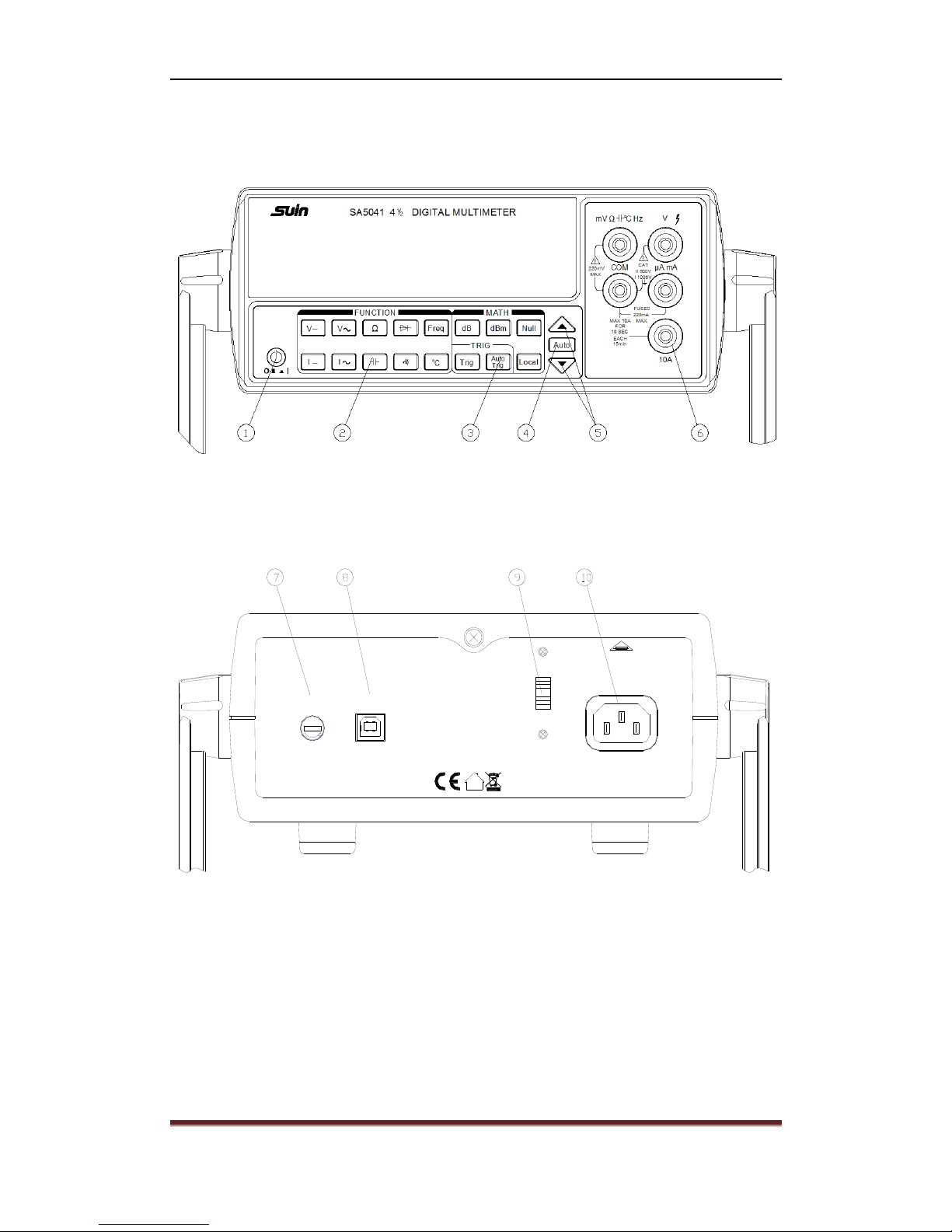
1.1 Front panel
①On/Off Switch ②Functional keys ③Auxiliary function keys ④Auto key
⑤Manual keys ⑥Input terminals
1.2 Rear panel
PUSE:F0.25AL,
250V
110V AC/220V AC
50Hz/60Hz 8VA
FUSE: F0.5AL 250V
USB Device
P
U
S
E
SHIJIAZHUANG SUIN INSTRUMENTS CO.,LTD.
REPLACE FUSE
AS SPECIFIED
DISCONNECT POWER CORD
BEFORE REPLACING FUSE
REPLACE FUSE
AS SPECIFIED
DISCONNECT POWER CORD
BEFORE REPLACING FUSE
⑦Current input fuse ⑧USB Device port ⑨110V/220V Switch ⑩Power socket
1.3 Service Guide
1.3.1 The meter is not available to power on
● Make sure that DMM is connected to AC power.
Confirm that the power cord is firmly connected to the power socket in the rear panel of meter.
● Confirm the voltage setting of power cord

SA5041 Digital Multimeter User’s Guide
Shijiazhuang Suin Instruments Co., Ltd 7
The voltage switch was set to match with the destination country when out of factory, but if the
voltage is different, please select the right one, which should be 110 or 220Vac.
● Check the fuse.
The fuse type is 500mAT, 250V.
1.3.2 Change the current input fuse
The first fuse is fast type melted fuse in the rear panel with specification of 250mA, 250Vac.
The second fuse is installed inside of meter with specification of 10A, 250Vac and which provides
10A current protection. User should open the case if the fuse needs to be changed.
Warning: In order to ensure the safety of the operator, use triple-core power socket
with ground wire.

SA5041 Digital Multimeter User’s Guide
Shijiazhuang Suin Instruments Co., Ltd 8
Chapter 2 Measurement Function
2.1 Measuring DC Voltage
Voltage Range: 200mV, 2V, 20V, 200V, 1000V
Max. Resolution: 10µV
Input Protection: 1000V (MAX)
Measuring method
(1) Insert the red test lead into the ‘V’ terminal (when measuring DC Voltage) or
‘mV/R/D/-||-/℃/Hz’ (when measuring DC mV Voltage) terminal and the black test lead into the
COM terminal.
(2) Press 【V-】key to select DC voltage, and make test lead parallel connected with object being
measured.
(3) Press 【▲】or 【▼】to select requested voltage range manually.And press 【AUTO】key to
lock auto range. (The range with mv unit could not be selected by pressing 【AUTO】key, only
with 【▼】key.)
(4) If ‘Over’ in display is lighten up, which means that measuring voltage beyond the setting range,
and press 【▲】key to set higher range until normal reading displayed.
(5) Reading is shown as the measuring voltage on the display.
(6) The input impedance of the Meter is around 10MΩ, which can cause measurement errors in
high impedance circuits. In most cases, the error could be negligible (0.1% or less) for circuit
impedance below 10KΩ.
(7) The input impedance is around 2GΩ for mV range measurement.
Note:
Do not input the voltage higher than 200mV when using mV range, or the instrument is
more likely to be damaged.
Do not input the voltage higher than DC 1000V to the input port.
Special care should be taken when measuring high voltage to avoid electric shock.
2.2 Measuring DC current
Current Range: 200µA, 2000µA, 20mA, 200mA, 10A
Max. Resolution: 0.01µA

SA5041 Digital Multimeter User’s Guide
Shijiazhuang Suin Instruments Co., Ltd 9
Input Protection: 0.25A, 250V fuse (for the measurement range below 200mA)
10A, 250V fuse (for the measurement range below 10A)
Measuring method
(1) Insert the red test lead into the μA mA or 10A terminal and black test lead into the COM
terminal. (Select 10A for high current, and select μA or mA for low current less than 1A)
(2) Press【I-】key to select DC current measurement, and make test lead series connected with
object being measured.
(3) Press【▲】or 【▼】key , and select current measuring range manually. Press 【AUTO】
key to lock automated measuring range.(【AUTO】key enables you to switch ranges between uA
and mA. 10Arange can only be selected by pressing 【▲】key. )
(4) If the “Over” light on, which means the measuring current value exceeds current range, press
【▲】to select a higher range until a normal reading show up.
(5) Reading is shown as the measuring current on the display.
Note:
Before make device series connected with measured circuit, please turn off the power of
circuit.
Please use correct terminal when measuring. If you can’t estimate the current value,
please start from the high range of current.
Continue measurement is allowed if ≤5A; the measuring time should be ≤10 second and
interval time should ≥15 minutes to meet safe use when the current is between 5A to
10A.
To avoid possible damage to the device and fuse, never place the testing leads in parallel
with any circuit or component when the leads are plugged into the current terminals.
When current measurement completed, first power off, then disconnect testing lead
with tested circuit and remove testing lead away from the input terminals of the Meter.
Fuse replacement
1. Cut off the power, disconnect the testing wire.
2. Rotate fuse holder with screwdriver counter-clockwise to pop-up the fuse
3. Replace fuse with the same specification

SA5041 Digital Multimeter User’s Guide
Shijiazhuang Suin Instruments Co., Ltd 10
4. Install it after replacement.
Warning: Never do the replacement with fuses over the specifications.
2.3 MeasuringAC Voltage
Voltage Range: 2V, 20V, 200V, 750V
Max. Resolution: 100µV
Input Protection: 750Vrms(MAX)
Measurement method:
(1) Insert the red test lead into the V terminal and the black test lead into the COM terminal.
(2) Press 【V~】key to measure AC voltage, and make test lead parallel connected with object
being measured.
(3) Press【▲】or 【▼】key, to select expected voltage measurement range manually. Press
【AUTO】key to lock the automated range, the light of which will be on after pressing.
(4) If the “Over” light on, it means the measuring voltage value exceeds current range, press【▲】
to select a higher range until a normal reading showed up.
(5) Reading is shown as measured current on the display.
Note:
Do not input the voltage overAC 700Vrms to input port.
Special care should be taken when measuring high voltage to avoid electric shock.
2.4 MeasuringAC Current
Current Range: 200µA , 2000µA, 20mA, 200mA, 10A
Max. Resolution: 0.01µA
Input Protection: 0.25A, 250V fuse (for the measurement range below 200mA)
10A, 250V fuse (for the measurement range below 10A)
Measuring method
(1) Insert the red test lead into the μA mA or 10A terminal and black test lead into the COM
terminal.
(2) Press 【I~】key, to measure AC current, the light of which will be on after pressing.
(3) Press 【▲】or【▼】key, to select the expected current measurement range manually.
Press【AUTO】key to lock the automated measuring range. (【AUTO】key enables you to switch

SA5041 Digital Multimeter User’s Guide
Shijiazhuang Suin Instruments Co., Ltd 11
ranges between uA and mA. 10A range can only be selected by pressing 【▲】key. )
(4) If the “Over” light on, it means the measuring current value exceeds current range, press【▲】
to select a higher range until a normal reading showed up.
(5) Reading is shown as measured current on the display.
Note:
Before make device series connected with measured circuit, please turn off the power of
circuit.
Please use correct terminal when measuring. If you can’t estimate the current value,
please start from the high range of current.
Continue measurement is allowed if ≤5A; 5A~10A continue measurement time; the
measuring time should be ≤10 second and interval time should ≥ 15 minutes to meet
safe use.
To avoid possible damage to the device and fuse, never place the testing leads in parallel
with any circuit or component when the leads are plugged into the current terminals.
When current measurement completed, first power off, then disconnect the testing lead
with circuit under test and remove testing lead away from the input terminals of the
Meter.
2.5 Two-line Resistance measurement
When testing low resistance, the resistance of the testing cable may cause certain error, the error
value caused by typical testing cable may range from 0.5 to 2Ω for two-line resistance.【NULL】
key could help user to correct this error.
Select two-line Ω function
Short the testing cable to get the resistance of testing cable.
Keep the short and press NULL key, the instrument displays 0Ω.
Resistance measurement
Resistance Range: 200Ω, 2.0kΩ, 20kΩ, 200kΩ, 2MΩ, 20MΩ
Max. Resolution: 0.01Ω
Measuring method
(1) Insert the red test lead into the ‘mV/R/D/-||-/℃/Hz’ terminal and the black test lead into the

SA5041 Digital Multimeter User’s Guide
Shijiazhuang Suin Instruments Co., Ltd 12
COM terminal.
(2) Press【Ω】key, to measure two-line resistance, the light of which will be on after pressing.
(3) Press 【▲】or【▼】key, and select expected voltage measuring range manually. Press
【AUTO】key to lock automated measuring range, the light of which will be on after pressing.
(4) If the “Over” light on, it means the measuring voltage value exceeds current range, press【▲】
to select a higher range until a normal reading showed up.
(5) Reading is shown as measured resistance on the display.
Note:
For open circuit or exceeding maximum range, the “Over” will light on.
Before measuring on-line resistance, make sure that turn off all power of inner
measured circuit. And run out of charge of all capacitors to guarantee correct
measurement.
When measuring low resistance, the test leads may cause an error range from 0.1Ω to
0.2Ω. For accurate measurement, short connect test lead and press 【Null】key to
automatically subtract this value.
For high-resistance (>1MΩ), normal measurement is not so fast, user may need a few
seconds to obtain a stable reading. User can short connect lead to get more stable
reading.
To avoid harms to user, please do not attempt to input voltage higher than 60V DC or
30VAC.
2.6 Capacitance Measurement
Capacitance Range: 20nF, 200nF, 2µF, 20µF, 200µF, 2mF, 20mF
Max. Resolution: 0.001nF
Input Protection: 1000V (MAX)
Measuring method
(1) Insert the red test lead into the ‘mV/R/D/-||-/℃/Hz’ terminal and the black test lead into the
COM terminal.
(2) Press【-||-】key to measure capacitance, the light of which will be on after pressing.
(3) Press 【▲】or【▼】key to select expected capacitor measurement range. Press【AUTO】

SA5041 Digital Multimeter User’s Guide
Shijiazhuang Suin Instruments Co., Ltd 13
key to lock automatic range, the light of which will be on after pressed.
(4) If the light of “Over” light on , it indicates that measured capacitor is over current range, press
【▲】key in this case to select higher range till the reading turn to be normal.
(5) Reading is shown as measured capacitance on the display.
Note:
The capacitance is required to be measured with short cable.
The measurement over 400μF may take more time than low capacitance.
To ensure accuracy, the Meter inside is discharged against the tested capacitor.
2.7 Frequency Measurement
Voltage Range A: 200mVrms≤A≤30Vrms
Frequency Range: 20Hz, 200Hz, 2000Hz, 20kHz, 200kHz, 2MHz, 20MHz, 200MHz
Max. Resolution: 0.001Hz
Input Protection: 750Vrms (MAX)
Measuring method
(1) Insert the red test lead into the ‘mV/R/D/-||-/℃/Hz’ terminal and the black test lead into the
COM terminal.
(2) Press 【Freq】key to measure frequency, the light of which will be on after pressing.
(3) Press 【▲】or【▼】key, and select expected frequency measuring range manually. Press
【AUTO】key to lock automated measuring range, the light of which will be on after pressing.
(4) If the light of “Over” light on , it indicates that measured voltage is over current range, press
【▲】key in this case to select higher range till the reading turn to be normal.
(5) Reading is shown as measured frequency on the display.
Note
The requirement of Input amplitude “A” is as follows:
When 10Hz ~ 40MHz: 200mVrms≤A≤30Vrms
> 40MHz: Un-specified
To avoid harms to user, please do not attempt to input tested frequency voltage higher
than 30V rms.
2.8 Diode measurement

SA5041 Digital Multimeter User’s Guide
Shijiazhuang Suin Instruments Co., Ltd 14
(1) Insert the red test lead into the ‘mV/R/D/-||-/℃/Hz’ terminal and the black test lead into the
COM terminal. The polarity of red test lead is ‘+’, while black test lead is ‘-‘.
(2) Press【 】 key to measure diode. Connect red test lead with positive polarity of tested diode
and black test lead with negative polarity of tested diode.
(3) In a circuit, a good diode should still produce a forward voltage drop reading of 0.5V to 0.8V.
Note
For open circuit of diode or wrong polarity connection, the “Over” will light on.
To avoid damages to the Meter or tested device, disconnect circuit power and discharge
all the high-voltage capacitors before testing diodes.
Open circuit voltage approximate 2.8V.
To avoid harms to you, please do not attempt to input voltages higher than 60V DC or
30VAC.
2.9 Short circuit measurement
Short circuit measurement is enabled by the 200Ω circuit of resistance function, the default critical
resistance is fixed as 10Ω, and once tested value less than this reference value, the buzzer will
make a sound.
Measurement Method
(1) Insert the red test lead into the ‘mV/R/D/-||-/℃/Hz’ terminal and the black test lead into the
COM terminal.
(2) Press【 】 key to measure short circuit, and make test lead parallel connected with two ends
of tested circuit. The buzzer makes a sound if resistance of two ends ≤10Ω.
(3) Reading is shown as tested load and unit is Ω.
Note:
When checking continuity, disconnect circuit power and discharge all the high-voltage
capacitors before measuring continuity. (是否需要保留?)
Open circuit voltage around –1.2V and selected range is 200Ω.
To avoid harms to you, please do not attempt to input voltage higher than 60V DC or
30VAC.
2.10 Temperature measurement

SA5041 Digital Multimeter User’s Guide
Shijiazhuang Suin Instruments Co., Ltd 15
Measurement Method
(1) Insert the red test lead of PT100 temperature probe into the ‘mV/R/D/-||-/℃/Hz’ terminal and
the black test lead into the COM terminal.
(2) Press 【℃】key to measure temperature.
(3) Reading is shown as measured temperature on display.
Note:
The temperature reading is not correct when the ambient temperature is out of range
from 12℃to 35℃. The error is more apparent when the instrument is placed in cold
environment.
The testing temperature range is from -200℃to 800℃.
To avoid harms to you, please do not attempt to input voltages higher than 60V DC or 30VAC.

SA5041 Digital Multimeter User’s Guide
Shijiazhuang Suin Instruments Co., Ltd 16
Chapter 3 Additional Functions
3.1 Return-to-zero Function
Operation guide
(1) Return-to-zero feature makes it possible for user to store a referenced reading, so the display is
a relative value. Press【Null】key to save current reading value, and the next displayed value is the
difference between measured value and this reference value. Null will light on under this function.
(2) Return-to-zero feature is compliant with all functions.
(3) Press【Null】key again to exit return-to-zero function, and Null will light off.
(4) If user change to other function, return-to-zero function will be disabled and character Null off.
3.2 Trigger function
Operation guide
(1) External trigger mode
External trigger mode is enabled by pressing the【Trig】key. Under this mode, there is not any old
data on the display, only if press the [Trig] key, the new measuring period enabled and new data
on the display. There is no trig function in frequency and capacitance.
(2) Press【Auto Trig】key to exit trigger mode.
3.3 Mathematical function
Mathematical function of this instrument means calculation of dB and dBm, only working under
AC voltage function.
(1) dB
dB is a unit of power gain. It is relative value. Formula as:
dBV=20log10Vin
(2) dBm
dBm is a unit of absolute value of power. Formula as:
dBm=10log10(Vin 2/REF)/1mW
REF takes 600Ω as granted.
Operating Method
(1) UnderAC voltage function, press 【dB】key to show dB value on the screen.
(2) UnderAC voltage function, press 【dBm】key to show dBm value on the screen.

SA5041 Digital Multimeter User’s Guide
Shijiazhuang Suin Instruments Co., Ltd 17
Chapter 4 Programming Guide
4.1 Interface operation
With the technology of Single-Chip USB to UART Bridge, the USB interface of the Meter realizes
the communication by series technology, and follows its setting. But if user don’t have the address,
please refer to following instructions to select COM port.
Operating instructions
1. Connect USB and device using USB cable, then click as per below sequence: My
computer→Right-click→Hardware→Device Manager→Port→CP2101 USB to UART Bridge
Controller (COMX)
2. Open the software then set serial interface as per PC prompt.
Note: Baud rate: 9600, Check bit: None, Data bit: 8 bits, Stop bit: 1
4.2 SCPI Commands
Command Keywords and Parameters
Command commands and SCPI commands have two types: parameters and non-parameters. Take
the followings as example:
*RST parameters
:FUNCtion <name> parameter <name> required
:IMMediate non- parameters
A space at least is needed between command keywords and parameter.
Square bracket [ ]: parameters enclosed in Square bracket are optional and could be
omitted. For example,
:RANGe[:UPPer] <n>
:UPPer is optional and you can send above command in one of following two formats,
:RANGe <n>
or :RANGe:UPPer <n>
Note: when using optional commands in your program, don’t include square bracket [ ].
Angular bracket < >: indicates this option is a parameter type. And < > should be
omitted when programming. For example,
[:SENSe]:CURRent:AC:RANGe:AUTO <b>
<b> indicates that a Boolean parameter required here. Thus, if enable Auto function in

SA5041 Digital Multimeter User’s Guide
Shijiazhuang Suin Instruments Co., Ltd 18
ACI, you must send the command with parameter 1or ON as below,
[:SENSe]:CURRent:AC:RANGe:AUTO 1
Parameter types:
<b> Boolean: Used to enable or disable an instrument operation. 0 or OFF
disables the operation; 1 or ON enables the operation.
CURRent:AC:RANGe:AUTO 1 enable AUTO range
<name> Name parameter: Select a parameter name from a listed group.For example,
:FUNCtion <name>
<name> = “VOLTage:AC” select AC voltage
“VOLTage[:DC]” select DC voltage
“CURRent:AC” select AC current
“CURRent[:DC]” select DC current
“RESistance” select 2-line resistance
“FREQuency” select frequency
“DIODe” select diode testing
“CONTinuity” select continuity testing
“TEMPerature” select temperature testing
<n> Numeric value:This parameter stands for an integer (take 6 for example),
numbers of real number (take 25.3 for example)
[SENSe[1]:CURRent[:DC]:NPLCycles 1
[SENSe[1]:CURRent[:DC]:NPLCycles 0.1
Command abbreviation rules
1. If the command length less than or equal to four characters, there is no abbreviation.
For example,
:AUTO=:AUTO
2. The rule is available for commands which longer than four characters.
3. If the fourth characters is v,o,w,e,l, then cancel it and all characters behind them.
For example,
:IMMediate=:IMM
4. Special rules –the abbreviation of the below command only uses the first two

SA5041 Digital Multimeter User’s Guide
Shijiazhuang Suin Instruments Co., Ltd 19
characters. For examples,
:TCcouple=:TC
5. When the fourth characters is consonant letters, remain it and cancel characters
behind them. For example,
:FORMat=:FORM
6. If the command contains query mark ‘?’ or an unselective numbers, then must remain
it in abbreviation format. For example,
:delay?=:del?
7. The commands or characters containing in Square is selective, which can be omitted
in code.
Command structure rules
1. Both uppercase and lowercase are allowed. For example,
FUNC VOLT:AC =func volt:ac= FUNC volt:AC
2. Space (which is shown by _) can be put back and forth of colon. For example,
FUNC “VOLT_:_AC” (wrong)
FUNC “VOLT:AC” (correct)

SA5041 Digital Multimeter User’s Guide
Shijiazhuang Suin Instruments Co., Ltd 20
3. Commands can be abbreviated or complete spelling. For example,
FUNCtion “VOLTage:AC”= FUNC “VOLT:AC”
4. Users can inquiry most parameters value on the condition of adding ‘?’ on behind of
command word. For example,
FUNC?
Command path rule
1. Each program must start from root commands unless the root command is optional.
(for example, : [SENSe] ). In this case, you can make next level command to be root
command.
2. If instrument detect a program with colon (:), it will move to next level command.
3. The command path can only go ahead from the one to next higher level. Once meet a
higher level command, it should be start from root command again.
Command reference
See below subsystem commands,
1)SENSe 2)SYStem 3) CALCulate 4)TRIGger
SENSe subsystem commands
FUNCtion command
:FUNCtion <name>
Command syntax: [:SENSe]:FUNCtion <name>
Parameter: <name> = “VOLTage:AC” select AC voltage
“VOLTage[:DC]” select DC voltage
“CURRent:AC” select AC current
“CURRent[:DC]” select DC current
“RESistance” select 2-line resistance
“FREQuency” select frequency
“DIODe” select diode testing
“CONTinuity” select continuity testing
“TEMPerature” select temperature testing
“CAPacitance”Select capacitance testing
Table of contents


