1-1. INTRODUCTION
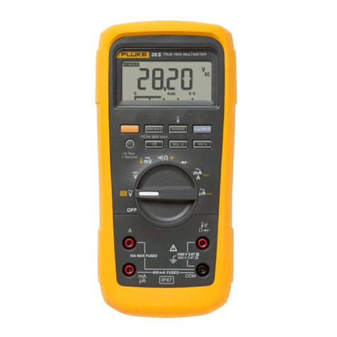
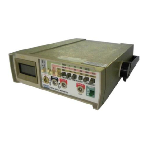
1-2. This eight-section manual provides comprehensive
information for installing, operating and maintaining
your Fluke digital multimeter. Complete descriptions and
instructions are included for the instrument mainframe,
for all modules necessary in making dc volts
measurements, and for any optional modules ordered
with the instrument. Appropriate sectionalized
information is also included with any optional modules
subsequently ordered and may be inserted in Section 6.
1-3. DESCRIPTION
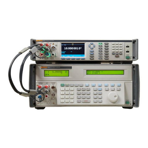
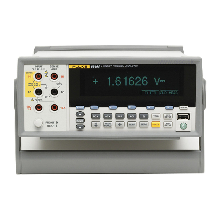
1-4. The multimeter features 6-1/2 digit resolution, full
annunciation and simplicity of operation. Modular
construction, microprocessor control, and abus structure
provide excellent flexibility. Memory programming from
the front panel (or through aremote interface) controls all
measurement parameters, mathematic operations and
special operations. An averaging mode is available to
automatically optimize display resolution and stability
for each function and range. The standard hardware
configuration allows for measurement of dc volts in five
ranges with 100 nV resolution on the lowest range.
Optional modules are available for ac volts (four ranges),
ac or dc current (five ranges), and resistance (eight ranges)
in two-wire or four-wire arrangements.
1-5. Modular Construction
1-6. Considerable versatility is realized through unique
contruction. All active components are contained in
modules which plug into amainframe motherboard. This
module-motherboard mating, combined with bus
architecture and microprocessor control, yields both ease
of option selection and reduced downtime.
NOTE
The A3 Isolator PCS is standard in the
8505A. This assembly is documented in
Section 6ofthis manual as Option -08A.
1-7. Microprocessor Control
1-8. All modules function under direct control of a
microprocessor based controller. Each module is
addressed by the controller as virtual memory. External
reference values and offsets can be applied separately,
stored in memory, and automatically used as factors in all
subsequent readings. Digital filtering utilizes averaged
samples for each reading.
1-9. Software Calibration
1-10. The 8505A features microprocessor-controlled
calibration of all ranges and functions. Any range can be
calibrated using areference input of any known value
from 60% of range to full scale. Software calibration can
be performed using front-panel or remote control,
allowing recertification without opening the case or
removing the multimeter from the system.
1-11. R@elreufating Remainder A/D Conversion
1-12. The multimeter adapts Fluke’s patented
recirculating remainder (R2)A/D conversion technique
to microprocessor control. This combination provides
fast, accurate, linear measurements and long-term
stability.
1-13. Options and Accessories
1-14. Remote interfaces, ac converters, acurrent
converter, and an ohms converter are among the
numerous options and accessories available for use with
the multimeter. Refer to Tables 1-1 and 1-2 for complete
listings. AC conversion can be accomplished with either
the AC Averaging module (Option 01) or the RMS
module (Option 09A). Any one of the three Remote
Interface modules (Option 05, 06, or 07) can be installed
at one time.
1-15. SPECIFICATIONS
1-16. Mainframe specifications with dc volts and dc
ratio measurement capability are presented in Table 1-3.
Optional function specifications are supplied with the
respective option modules and included in Section 6.

