Shimax MAC3 Series User manual

1
「
「「
「Notice」
」」
」
Pleaseensurethatthis manual is given to thefinaluser of the instrument.
Contents
Page
Preface ・・・・・・・・・・・・・・・・・・・・・・・・・・・・・・・・・・・・・・・・・・・・・・・2
1.Mattersregardingsafety・・・・・・・・・・・・・・・・・・・・・・・・・・・・・・・・・・・・・・・・・2
2. Introduction ・・・・・・・・・・・・・・・・・・・・・・・・・・・・・・・・・・・・・・・・・・・・・2
2-1.Checkbeforeuse ・・・・・・・・・・・・・・・・・・・・・・・・・・・・・・・・・・・・・・・・・・2
2-2.Caution for use ・・・・・・・・・・・・・・・・・・・・・・・・・・・・・・・・・・・・・・・・・・・2
3. Installationandwiring ・・・・・・・・・・・・・・・・・・・・・・・・・・・・・・・・・・・・・・・・・3
3-1. Installation site(environmentalconditions)・・・・・・・・・・・・・・・・・・・・・・・・・・・・・・・・・3
3-2.Mounting・・・・・・・・・・・・・・・・・・・・・・・・・・・・・・・・・・・・・・・・・・・・・・3
3-3.External dimension andpanelcutout ・・・・・・・・・・・・・・・・・・・・・・・・・・・・・・・・・・・3
3-4.Wiring ・・・・・・・・・・・・・・・・・・・・・・・・・・・・・・・・・・・・・・・・・・・・・・3
3-5.Terminalarrangementdiagram ・・・・・・・・・・・・・・・・・・・・・・・・・・・・・・・・・・・・・4
4. Description of front panel ・・・・・・・・・・・・・・・・・・・・・・・・・・・・・・・・・・・・・・・・4
4-1.Names offrontpanel ・・・・・・・・・・・・・・・・・・・・・・・・・・・・・・・・・・・・・・・・・4
4-2.Explanationoffrontpanelsection ・・・・・・・・・・・・・・・・・・・・・・・・・・・・・・・・・・・・4
5. Description of screens ・・・・・・・・・・・・・・・・・・・・・・・・・・・・・・・・・・・・・・・・・5
5-1.Howtomovetoanotherscreen ・・・・・・・・・・・・・・・・・・・・・・・・・・・・・・・・・・・・・5
5-2.SettingMethod ・・・・・・・・・・・・・・・・・・・・・・・・・・・・・・・・・・・・・・・・・・・5
5-3.Power-on andinitialscreendisplay・・・・・・・・・・・・・・・・・・・・・・・・・・・・・・・・・・・・5
5-4.Explanationofeach screen・・・・・・・・・・・・・・・・・・・・・・・・・・・・・・・・・・・・・・・5
(1)Basicscreens・・・・・・・・・・・・・・・・・・・・・・・・・・・・・・・・・・・・・・・・・・・・5
(2)FIX(constantvaluecontrol)settingscreens ・・・・・・・・・・・・・・・・・・・・・・・・・・・・・・・・7
(3)PROG(programcontrol)settingscreens ・・・・・・・・ ・・・・・・・・・・・・・・・・・・・・・・・・7
(4)Mode1screens・・・・・・・・・・・・・・・・・・・・・・・・・・・・・・・・・・・・・・・・・・・9
(5)Mode2screens・・・・・・・・・・・・・・・・・・・・・・・・・・・・・・・・・・・・・・・・・・・9
(6)Mode3screens・・・・・・・・・・・・・・・・・・・・・・・・・・・・・・・・・・・・・・・・・・・9
(7)Mode4screens ・・・・・・・・・・・・・・・・・・・・・・・・・・・・・・・・・・・・・・・・・・10
(8)Mode5screens ・・・・・・・・・・・・・・・・・・・・・・・・・・・・・・・・・・・・・・・・・・11
(9)Mode6screens ・・・・・・・・・・・・・・・・・・・・・・・・・・・・・・・・・・・・・・・・・・12
(10)Mode7screens ・・・・・・・・・・・・・・・・・・・・・・・・・・・・・・・・・・・・・・・・・・13
(11)Mode8screens ・・・・・・・・・・・・・・・・・・・・・・・・・・・・・・・・・・・・・・・・・・13
(12)Mode9screens ・・・・・・・・・・・・・・・・・・・・・・・・・・・・・・・・・・・・・・・・・・13
5-5.Measuringrangecodetable ・・・・・・・・・・・・・・・・・・・・・・・・・・・・・・・・・・・・・・14
6. SupplementaryExplanationofFunction・・・・・・・・・・・・・・・・・・・・・・・・・・・・・・・・・・・14
6-1. Autoreturnfunction・・・・・・・・・・・・・・・・・・・・・・・・・・・・・・・・・・・・・・・・・・14
6-2.Output Soft StartFunction ・・・・・・・・・・・・・・・・・・・・・・・・・・・・・・・・・・・・・・・14
6-3.EventSelectionAlarmOperation Figure・・・・・・・・・・・・・・・・・・・・・・・・・・・・・・・・・・14
6-4. AT (AutoTuning) ・・・・・・・・・・・・・・・・・・・・・・・・・・・・・・・・・・・・・・・・・・14
6-5.2output-characteristicsfigure ・・・・・・・・・・・・・・・・・・・・・・・・・・・・・・・・・・・・・14
7. Trouble Shooting ・・・・・・・・・・ ・・・・・・・・・・・・・・・・・・・・・・・・・・・・・・・・・15
7-1.CauseandTreatment ofMainDefects ・・・・・・・・・・・・・・・・・・・・・・・・・・・・・・・15
7-2.CauseandTreatment ofError Display・・・・・・・・・・・・・・・・・・・・・・・・・・・・・・・・・・・16
8. Specification ・・・・・・・・・・・・・・・・・・・・・・・・・・・・・・・・・・・・・・・・・・・・・16
9. Programpatternsettingtable ・・・・・・・・・・・・・・・・・・・・・・・・・・・・・・・・・・・・・・・20
MAC3F-1 AE January, 2005
MAC3
MAC3MAC3
MAC3 Series
SeriesSeries
Series
Digitalcontroller InstructionManual
Thankyoufor purchasingSHIMAX product.Pleasecheck thatthe productisthe one youordered.
Pleaseoperateafter youread theinstruction manualand fully understand it.

2
Preface
This instruction manual is intended for those who will be involved in wiring, installation,
operationandroutinemaintenanceoftheMAC3.
This manual describes the care, installation, wiring, function, and proper procedures
regardingtheoperationofMAC3.
Keep thismanualonhandwhileusingthisdevice. Please followtheprovided guidance.
1.
Mattersregardingsafety
For matters regarding safety, potential damage to equipment and/or facilities and additional
instructionsareindicatedasfollows:
This mark indicates hazardous conditions that could cause injury or death of personnel.
Exerciseextreme cautionasindicated.
「
「「
「
WARNING」
」」
」
This mark indicates hazardous conditions that could cause damage to equipment and/or
facilities.Exercise extremecautionasindicated.
「
「「
「
CAUTION」
」」
」
Thismark indicatesadditionalinstructionsand/or notes.
「NOTE」
「
「「
「
WARNING」
」」
」
MAC3 isdesignedforcontrollingtemperature,humidity,andother physicalsubjectsingeneral
industrialfacilities.Itmust not beusedinany waythatmayadverselyaffectsafety, health,or
workingconditions.
「
「「
「
CAUTION」
」」
」
To avoid damageto the connected equipment, facilities or the product itself due to a fault of
thisinstrument, safety countermeasures must be taken beforeusage, suchas proper installation
ofthefuseandtheoverheatingprotectiondevice.Nowarranty,expressedorimplied,isvalidin
thecaseofusagewithout havingimplementedpropersafetycountermeasures.
「
「「
「
CAUTION」
CAUTION」CAUTION」
CAUTION」
Themarkontheplateaffixedtotheinstrument:
On the terminal nameplate affixed to the case of your instrument, the mark is printed.
Thisistowarn you of therisk of electrical shock which may resultif thecharger istouched
whileitisenergized.
The external power circuit connectedto the power terminal ofthisinstrument must havea
means of turning off the power,such asa switch or breaker. Install the switchor breaker
adjacent to theinstrument in a position which allows it to be operated with ease, and with
an indication that it isa means of turning off the power. Use a switch or breaker, which
meetstherequirementsofIEC127.
Fuse:
Since the instrument does not have a built-in fuse, do not forget to install a fuse in the
power circuit to be connected to the power terminal. The fuse should be positioned
between the switch or breaker and the instrument and should be attached to the L side of
thepowerterminal.
Fuse Rating:250VAC0.5A/mediumlaggedorlaggedtype.
Usea fuse which meetsthe requirements ofIEC127
Load voltage/current to be connected tothe output terminalandthe alarm terminal should
be within the rated range. Otherwise, the temperature will rise and shorten the life of the
productand/or resultinproblems withtheproduct.
Voltage/current that differs from input specification should not be connected to the input
terminal.Itmayshortenthelifeoftheproductand/orresult inproblems withtheproduct.
Input, output ofvoltage pulse, and output of electric current are not insulated. Therefore, do
notgroundanadjusted power terminal whena groundsensorisemployed.
A signal wire's common mode voltage to ground (signal wires other than contact output
includingpower supply and event) shouldbelessthan 30Vrms, 42.4Vpeak,and60VDC .
「
「「
「
CAUTION」
」」
」
All the wires for the interior distribution, except for communication and contact output (including
power supplyand event), should be lessthan30minlength.Whenthe wire'slength is 30mor more,
orinthe caseofoutdoor wiring,the suitablemeasureagainsta lightningsurgeisrequired.
EMC standard (IEC61326) classifies MAC3 into Class A apparatus. Electromagnetic interference
may occur when MAC3 is used at a business district or in the home. Please use after taking
sufficientmeasures.
2. Introduction
2-1. Checkbefore use
BeforeusingMAC3,please checkthemodel code,theexteriorappearanceand accessories. Also,
makesurethatthereare no errors, impairsand shortages.
Confirmationofmodelcode:Checkthattheproductyou orderedisbeingdeliveredproperly.
Check themodelcodeofthemainbodycaseagainstthe followingcodetable.
Example of modelcode
MAC3A-
MAC3A-MAC3A-
MAC3A- M
MM
MC
CC
C
F-
F-F-
F- E
EE
E
C-
C-C-
C- D
DD
D
H
HH
H
T
TT
T
R
RR
R
N
NN
N
1 2 3 4 5 6 7 8 9 10
11
Item
1.Series MAC3A-:96×96mmsizedigitalcontroller
MAC3B-:48×96mmsizedigital controller
2.Input M:multi,V:voltage,I:current
3.ControlOutput1 C:contact,S:voltagepulse,I:current(4~20mA),V:Voltage(0~10V)
4.Power Supply F-:90-264VAC,L-:21.6 -26.4VDC/AC
5.EventOutput N:none,E:EventOutput1・2(twopoints)
6.ControlOutput 2・EventOutput・OptionalSelectionofDI
N-:none,C-:contact,S-:voltagepulse,I-:current(4~20mA),V:Voltage(0~10V)
E-: Event Output3(one point), D-: externalcontrolinput(DI4) one point
7.DI N:none,D: external control input(DI1,2,3)threepoints8
8. CT Input N:none,H: CT Inputtwo points
9.AnalogOutput N:none,I: current(4~20mA)
10.Communication N: none, R:RS485
11.ProgramFunction N:none, P:equipped
Example of model code
MAC3D-
MAC3D-MAC3D-
MAC3D- M
MM
MC
CC
C
F-
F-F-
F- E
EE
E
C-
C-C-
C- D
DD
D
T
TT
T
N
NN
N
1 2 3 4 5 6 7 8 9
Items
1.Series MAC3C:72×72mmsizedigitalcontroller
MAC3D-:48×48mmsize digital controller
2.Input M:multi,V: voltage, I:current
3.ControlOutput1 C:contact,S:voltagepulse,I:current(4~20mA)V:Voltage(0~10V),
4.Power Supply F-:90-264VAC,L-:21.6-26.4VDC/AC
5.EventOutput N:none,E:EventOutput1・2(two points)
6.ControlOutput2・EventOutput・OptionalSelectionofDI
N-:none,C-:contact,S-:voltagepulse, I-:current(4~20mA)V:Voltage(0~10V)
E-: Event Output3(one point), D-: externalcontrolinput(DI4) one point
7.DI・CT Input N:none, D: externalcontrolinput(DI1,2,3)three points,H:CT Inputtwo points
8.AnalogOutput・Communication N:none,T:current(4~20mA),R:RS485
9.ProgramFunction N:none, P:equipped
Check ofaccessories
Instruction manual:1 set
「NOTE」: Please contactour agencies or business officesifyou have anyproblem.
Wewelcomeanykind ofinquirysuchasdefectoftheproduct, shortageofaccessory
andsoon.
2-2.Cautionforuse
(1) Do not operatethefront panel keys with hard or sharpobjects.
Donot failto touchkeyslightlywitha fingertip.
(2)Wipegentlywitha dryragandavoidusing solventssuchasthinner.
3.Installationandwiring
3-1. Installationsite (environmentalconditions)
「
CAUTION」
Donot usethisproductunderthefollowingconditions.
Otherwise,failure,damageand firemay occur.
(1) Where flammable gas,corrosive gas, oil mist or dust generateor growrife.
(2)Wherethetemperatureisbelow-10℃orabove55℃
(3)Wherethe humidityisover90%RH orwherecondensationoccurs.
(4)Wherehighvibration or impactoccurs
(5)Whereinductiveinterferencemayeasilyaffect theoperation.
Or,intheregion of strongelectriccircuitarea.
(6) Where waterdropsor direct sunlightexists.
(7)Wherethealtitudeisabove2,000m.
「NOTE」:Theenvironmentalconditions comply withtheIEC664.
InstallationcategoryisⅡandthe pollution degreeis2.

3
3-2. Mounting
(1)Machinethemounting holebyreferring tothepanel-cutillustrationinSection3-3.
(2)Applicablethicknessofthemountingpanelis1.2~ 2.8mm.
(3)As thisproductprovides mounting fixture, inserttheproductintothepanel.
3-3. Externaldimensionand panelcutout
MAC3 externaldimensions(unit:mm)
MAC3panelcutout(unit:mm)
MAC3A 96×96size
92
+0.8
-0
92
+0 . 8
-0
(9 6 ×N - 4)
+0 . 8
-0
96 以 上
92
+0 . 8
-0
96 以 上
In the case of horizontal proximityattachment by a single hole
N:
Number
MAC3B 48×96size
48 以 上
96 以 上
9 2+0.8
-0
45
+0.6
-0
( 48 × N - 3)
+0.6
-0
92+0 . 8
-0
In the caseof horizontal proximity attachment by a single hole
N:
Number
MAC3C 72×72size
MAC3D 48×48size
45
+0 . 6
-0
45
+0 . 6
-0
4 8 以 上
( 4 8 × N - 3 )
+0 . 6
-0
45
+ 0. 6
- 0
48 以 上
Inthe case of horizontal proximityattachment by a single hole
N:
Number
Note:Proximityattachment bya singleholeispossibleonlyinthe case ofhorizontaldirection.
When an apparatus that was attached in vertical direction is removed, a dedicated detachment
tool isrequired.
3-4.
3-4.3-4.
3-4.Wiring
「
「「
「
WARNING」
」」
」
◎Donotturnonelectricity while wiringtoavoidanelectricshock.
◎Donot touchaterminalor livepart whileturningonelectricity.
(1)Makesurethatwiring operation isproperly doneinlinewitha terminalwirediagramofsection3-5.
(2)Choosea suitablecompensationleadwireinthecaseofthermocoupleinput.
(3)Inthecase ofresistancebulbinput,resistancevalueofeachleadwiremust belessthan
5Ωandthatofthreelead wiresmust be equal.
(4)Donot wiresaninputsignallineinsideofanelectricwirepipeora ductsamewiththe
highvoltage line.
(5)Shieldwiring(singlepoint grounding) is effectiveagainst staticinductionnoise.
(6)Wiringtwistedatequalshortintervalsiseffectiveagainstelectromagneticinduction noise.
M
96
AC
3
MAC3A
MAC3B
MAC3B
MAC3D
96
69
96
48
66
96
72
69
72
48
48
66

4
3-5.
3-5.3-5.
3-5.Terminalarrangementdiagram
3-5.Terminalarrangement planofMAC3AandMAC3B
OUT2/EV3/DI4
1
2
3
4
5
6
7
8
9
10
11
12
13
14
15
16
17
18
19
20
21
22
23
24
DI1
DI2
DI3
AO
+
-
EV2
EV1
INPUT
L
N
POWER
OUT1
90-264V AC
50/60Hz 9VA
COM
+
-
CT1
CT2
~
~
~
~
+
-
A
B
B
RS-485
+
-
+
-
CONTACT:240V AC 2A
SSR DRIVE:12V DC 20mA
CURRENT:4-20mA DC
CONTACT:240V AC 2A
SSR DRIVE:12V DC 20mA
CURRENT:4-20mA DC
EV3:240V AC 2A
240V AC 2A
240V AC 2A
L +
N -
POWER
21.6-26.4V DC
4W
50/60Hz 6VA
21.6-26.4V AC~
COM
VOLTAGE:0-10V DC
VOLTAGE:0-10V DC
「Note」: If input type is thermocouple or voltage, errors may occur when terminal 11 and
terminal12terminalare short-circuited
Terminalarrangement planofMAC3C
1
2
3
4
5
6
10
11
12
13
14
15
16
17
18
EV2
EV1
DI1
DI2
DI3
AO
+
-
COM
+
-
CT1
CT2
~
~
~
~
L
N
POWER
OUT1
90-264V AC
50/60Hz 9VA
OUT2/EV3/DI4
INPUT
+
-
A
B
B
CONTACT:240V AC 2A
SSR DRIVE:12V DC 20mA
CURRENT:4-20mA DC
+
-
+
-
CONTACT:240V AC 2A
SSR DRIVE:12V DC 20mA
CURRENT:4-20mA DC
EV3:240V AC 2A
240V AC 2A
240V AC 2A
COM
7
8
9
19
20
21
22
23
24
25
26
27
L +
N -
POWER
21.6-26.4V DC
4W
50/60Hz 6VA
21.6-26.4V AC~
VOLTAGE:0-10V DC
VOLTAGE:0-10V DC
「Note」: If inputtypeisthermocouple or voltage, errors may occur when terminal 8 and
terminal9terminalareshort-circuited
TerminalarrangementplanofMAC3D
1
2
3
4
5
6
7
8
9
10
11
12
13
14
15
16
17
18
EV2
EV1 DI1
DI2
DI3
AO
+
-
COM
+
-
CT1
CT2
~
~
~
~
L
N
POWER
OUT1
90-264V AC
50/60Hz 9VA
OUT2/EV3/DI4
INPUT
+
-
A
B
B
CONTACT:240V AC 2A
SSR DRIVE:12V DC 20mA
CURRENT:4-20mA DC
+
-
+
-
CONTACT:240V AC 2A
SSR DRIVE:12V DC 20mA
CURRENT:4-20mA DC
EV3:240V AC 2A
240V AC 2A
240V AC 2A
L +
N -
POWER
21.6-26.4V DC4W
50/60Hz 6VA
21.6-26.4V AC~
COM
VOLTAGE:0-10V DC
VOLTAGE:0-10V DC
「Note」:Ifinputtypeisthermocouple or voltage, errors may occur whenterminal 5 and
terminal 6 terminalareshort-circuited
4.
4.4.
4..Descriptionoffrontpanel
4-1.
4-1.4-1.
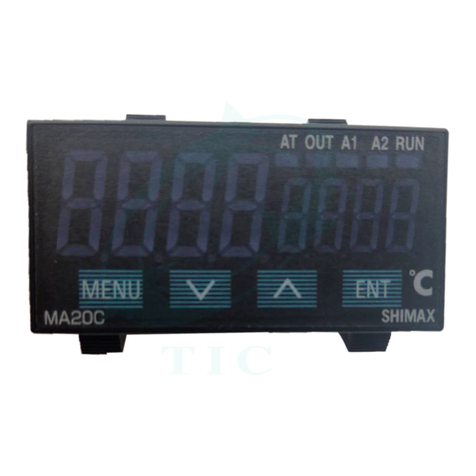
4-1.Namesoffrontpanel.
MAC3A 96×96size front MAC3C72×72size front
MAC3D 48×48size front MAC3B48×96 size front
4-2.Explanationoffront panelsection
① :Displayofmeasuredvalue(PV) (red)
Measured value(PV) andtypeofsettingisdisplayedoneachsettingscreen.
②:Displayoftarget value(SV) (green)
Target valueand set valueare displayedon eachsettingscreen.
③:MonitorLED
(1)RUN monitor LED RUN (green)
IfRUN isperformed with RUN key, operation mode1 screen, external control input (DI),and
communication, it lights up, and put out by standby (reset). It blinks, if a manual output is
choseninoutput monitoringscreenor externalcontrol input (DI).
(2)Programfunctionalmonitor LED PRG (green)
Lightsup at the time of program control's standby or flat part control. Puts out at the time of
FIXcontrolselection.
(3)AutotuningoperationmonitorLED AT (green)
If AT is chosen in ON or external control input (DI), blinks during AT execution. Lightsup
when ATisonstandby,andputsoutwithATautomaticterminationorrelease.
(4)controloutput1 monitorLED OUT (green)
At thetimeofa contact ora voltage pulseoutput,theitlightsupwith ONandlightsoff with
OFF.Lightsoffwith0%poweroutput,andlightsupwith100%power.
Andblinksinintermediateratio.
(5)Eventoutput monitorsLED EV1andEV2 (yellow)
Lightsupwhentheallottedeventoutput turnstoON.
(6)Controloutput 2/eventoutput3 monitorsLED OUT2/EV3 (yellow)
Whencontrol output2 ischosen, it operateslikecontrol output1 monitor LEDdoes.
Whenevent output3 ischosen,itoperateslikeeventoutput monitorLEDdoes.
④: Key-switchsection
(1)
(MENU)key
Pressthiskeytomoveontothenextscreenamong thescreens.
Press
(MENU)key for three secondsonthe basicscreen,then it jumpsto the
lead screen of Mode1. Press
keyfor threeseconds on thelead screen ofeach
Modescreens,thenitjumps tothe basicscreen.Press
keyforthreesecondson
the lead screen of FIX or PROG, then it jumps to the basic screen.When a
program control option is added, press
(MENU) key for three seconds on the
screenofoperationmode2,thenitjumpstothescreenofoperationMode1.
(2)
(DOWN)key
Press
(DOWN)key onetime,andtheshownvaluedecreasesbyonenumericalvalue.
One time press of
key decreases by one numerical value. By pressing the key
continuously, the valueas well consecutively decreases. A decimal point of the smallest digit
blinks at this time. This shows thata settingchange isinprogress.InPROG,usedasa shiftkey
between each step setting screens(Steps1-25) ,lead screen.Also used as a shift key between
leadscreenineachmodescreens.
(3)
(UP) key
Press
(UP)key onetime,and theshownvalueincreasesbyonenumerical value.
By pressing continuously, the value By pressing the key continuously, the value consecutively
increases. A decimal point of the smallest digit blinks at this time. This shows that a setting
change is in progress. In PROG,used as a shift key between each step setting screens (Steps
1-25), lead screen. Also usedasa shiftkeybetween lead screenin each mode screens.
(4)
(ENTRY/REGISTER)key
The setting data changed on each screen is determined (the decimal point of the minimum
digitisalsolightedoff).
When aprogramcontrol option is added,press
(ENT)keyforthreesecondsonthescreen
ofoperation mode1,thenitjumpstothe screenofoperationMode2.
Press
key for 3 seconds on the output monitoring screen,then the shift between manual
outputandautomaticoutputiscarriedout.
Press thekey for3 secondsonthe basicscreen,then it shifts to FIXor PROG head screen.
PushatFIX-PROGandeachmodescreens'leadscreen,thenshiftstosettingscreen.
(5)
(RUNOPERATION/STOP)key
Push for 3 secondsatSTBY (controlstop),thenFIXorPROG control starts.
Push for3 secondswhileFIX or PROG is in operation,thencontrolisstopped.
①
②
③
④
①
②
③
④

5
5. Description of screens
5. Description of screens5. Description of screens
5. Description of screens
5
55
5-
--
-1. How to move to another screen
1. How to move to another screen1. How to move to another screen
1. How to move to another screen
Basic Screen
3 seconds (constant value control) lead screen of setting screens or (Program control) lead screen of setting screens
3 seconds
Press the key for 3 seconds on a basic screen, then it shifts to the lead screen of (constant value control) setting screens, or to the lead screen of (program control) setting screens.
Press the key for 3 seconds on or the lead screen of setting screens, then it shifts to the basic screen..The shift is also possible when the program option is added and is chosen on the
operation mode 2 screen. The shift is possible when the program option is added and is chosen on the operation mode 2screen.
Basic Screens
Mode 1 ~ 9 screens
Basic Screen
Mode 1 lead screen Mode 2 lead screen Mode 9 lead screen
three seconds
three seconds
Operation mode 1 key lock PV offset correction
Every time you press the key on a basic screen, it shifts to each screen of the basic screens.
Press the key for 3 seconds on a basic screen, then it shifts to the lead screen of mode 1 screens.
Press the key on the lead screen of mode 1 screens , then it further advances to mode 2, and mode 3. (Notes: If no corresponding option is found, the mode 4 - 9 is skipped)
Press the key on the lead screen of mode 1 screens , then it further advances to mode 9, and mode 8. (Notes: If no corresponding option is found, the mode 4 - 9 is skipped)
Press the key for 3 seconds on the lead screen of mode 1~ 9 screens, then it shifts to the basic screen.
Press the key on the lead screen of mode 1~ 9 screens, then it shifts to the first setting screen of each screens.
Press the key on the the first setting screen of each screens, then it shifts to the next screen. Every time you press the key, it shifts to the next setting screen.
5
55
5-
--
-2. Setting Method
2. Setting Method2. Setting Method
2. Setting Method
To change settings, display an appropriate screen and change the setting (value or function) by pressing or key.
On the output monitor screen of basic screens, you can change the control output from "Automatic" to "manual" ,and save its change of setting. Display the output monitor screen, and then press key for
three seconds to shift from Automatic to Manual. Then by pressing or key, you can adjust to the desirable output value. In this case, no need to press key in order to determine the change of setting.
Press key for three seconds as well to shift back to Automatic. Excluding when a keylock is OFF, Automatic⇔Manual switchover does not work while STBY<RST> and AT are in operation.
In the case of two-output type, the switchover between automatic and manual is operatable through output 1 and output 2. The setting is altered simultaneously.
Output monitor Output monitor Output monitor
three seconds
or
Automatic screen RUN lamp lights up Manual screen RUN lamp blinks Manual screen RUN lamp blinks
5
55
5-
--
-3. Power
3. Power3. Power
3. Power-
--
-on and initial screen display
on and initial screen displayon and initial screen display
on and initial screen display
At power-on, the display section shows each screen of initial screens for one second , then moves on to the basic screen.
《Power-on》
All LED light up Input type Upper limit & lower limit of measuring range Out 1 type ※
※※
※ Out 2 type Basic screen
:Contact :Voltage pulse :Current ※
※※
※Output 2 Displays only optional addition.
5
55
5-
--
-4. Explanation of each scre
4. Explanation of each scre4. Explanation of each scre
4. Explanation of each scre
(1) Basic Screens
Basic Screen
Executed SV initial value:Sensor input 0
Linear input Lower limit of scaring range
Setting range:Sensor input Within measuring range
key Linear input With in scaring range
Within SV limiter besides
Targeted value (PV) is displayed on the upper row as four-digit ,and target d
value (SV) is displayed on the lower row also as four-digit. (Notes:hereinafter,
measured value and targeted value are referred to as"PV" and "SV")
At the time of FIX, execution SV is displayed and change of setting is possible.
PROG's SV is just displayed ,and change of setting is impossible.
Action Mode 1 screen
Initial value::(stanby)(Initial value at the time of constant value control)
(reset)(Initial value at the time of program control)
Setting range::() Control stop [Output OFF (0%)] operation
key conduct of control operation
Choose (RUN) by key. Decide by key, then Monitor LED's RUN lights up to
start control operation.
Choose ()by key、Decide by key, hen Monitor LED's RUN lights off
and becomes control stop [Output OFF (0%)] conducting.
Priority is given to DI when RUN is allotted to external control input. DI. Key operation cannot be
performed unless allotment is canceled.
When measuring range, a unit, scaling, and output characteristics are changed it is initialized and
() is displayed.
Press key for 3 seconds, then it shifts to Action mode2 screen,when the program control
option is added on this screen, FIX (constant value control) ←→PROG (program control)
switchover is possible choose.
Choose a program,then Monitor LED's PRG lights up.
Action mode1 screen Action mode2 screen
three seconds
three seconds
three seconds PRG LED lights up
Press key for 3 seconds on Action mode2 screen, then it returns to Action mode1 screen.
Action mode2 screen is not displayed without a program option.
When PROG is allotted to DI, DI is given priority. Key operation cannot be performed unless
allotment is canceled.
Press key on Action mode1 screen, then it shifts to output 1 monitoring screen.

6
Output 1 monitoring screen
manual output setting range: :0.0-100.0% (within output limiter)
At the time of automatic output,monitor display only.
key Refer to Item 5-2 about automatic ⇔ manual switchover,and setting method at the
time of manual operation.
A manual output is canceled when an operation mode is made into ().
When a power source is intercepted and re-switched on, it returns to the condition just before
intercepting.
When is allotted to DI, DI is given priority. Automatic ma ⇔ manual switchover
is not performed with key operation,and only the output value at the time of manual
operation can be changed.
Output 2 monitoring screen
Contents are the same with that of an output 1.
key Output 2 monitoring screen displays only when output 2 option is added.
CT1 current monitoring-screen
Current display range: 0.0-55.0A
Displays at the time of CT input option addition, and the current value detected by CT
sensor is displayed.
key Current value is displayed.
CT2 current monitoring screen
Contents are the same with that of an output 1.
key
Monitoring screen of step's remaining time period
:
::
: Displays while program is in operation if program option is added.
key Step № in progress and remaining time are displayed by turns.
(In ∞ setting, step № and are displayed by turns)
A remaining time and an elapsed time is switchable by pressing the key for 3 seconds.
(Switchover is interlocked with the number of times of next screen pattern.)
Decimal point of the minimum digit lights up in displaying elapsed time,
This screen is not displayed without a program option.Not displayed in the state of
program RST and FIX neither.
Monitoring screen for the remaining repeating time of pattern
Being displayed while program is in operation, when the program option is added,
On-going step № and the remaining repeating time of pattern are displayed by turns.
key (In ∞ setting, step № and are displayed by turns)
A remaining time and actually performed times are switchable by pressing the key
for 3 seconds. (Switchover is interlocked with front screen step time.)
The decimal point of the minimum digit lights up when actually performed times being displayed.
This screen is not displayed without a program option.Not displayed in the state of
Program RST and FIX neither.
PID № monitoring screen
Chosen PID № is displayed when FIX is in operation.
PID № chosen at each step and on-going step № are displayed by turns when PROG
key is in operation.
PID № of output 1 is displayed in the first digital, and PID № of output 2 is displayed in
the third digital. The third digital is shown as when there is no output 2 option.
This screen is not displayed in the state of STBY (RST).
HOLD (temporary stopping) execution screen
Initial value::
Setting range::、
While HOLD is executed, on the basic screen,SV value and is displayed by turns . If
switched while PROG is in operation , the operation temporary stops with
as of then step time and SV value. While HOLD is in execution , SV value and
is displayed by turns in basic screen.、
HOLD is used in order to perform AT in the middle of an inclination step or to compensate the
insufficient time of flat step.
Controls is performed with SV value at the time of stopping,while HOLD is in execution
HOLD is canceled if is chosen while HOLD is in execution. The remaining time
of the step is performed based on a program.
(skip)is unable to perform while HOLD is in execution.
When is allotted to DI, DI is given priority.
Execution and release of HOLD with key operation is unable to perform.
This screen is not displayed without a program option.Not displayed in the state of program
and FIX neither.
SKIP (skip) execution screen
Initial value::
Setting range::、
SKIP (skip) is the function that makes to end the on-going step compulsorily, and is to shift to
the following step. The next step starts instantly, if performed.
When SKIP is continuously performed, about 1 second interval is required from execution to the
next one.
Even if SKIP is allotted to DI, execution is able to perform with DI and key operation.
key SKIP cannot be performed while HOLD is in operation.
This screen is not displayed without a program option. Not displayed in the state of
program
and FIX neither.
AT (Auto Tuning) execution screen
Initial value::
Setting range::、
key
AT is performed by ON selection ,and canceled by OFF selection.
Not displayed at the time of STBY(RST), a manual output, and P(proportional band) =OFF.
Except in the setting of keylock OFF, AT is unable to perform in scale over.
(At the time of DI allotment,execution of AT by DI can be performed .)
Even in such a case,halfway release is performed on this screen.
Release of AT, STBY(RST), EV operating point, setting of keylock, and mode 5 ~
9screen are operateable with key.
Except in th setting of AT normal end, execution of AT is canceled compulsorily at the time
of STBY(RST) selection and AT release setup.
EV1 (event 1) operating-point setting screen
Initial value: upper limit absolute value measuring range Scaling upper limit
lower limit absolute value measuring range Scaling lower limit
upper limit deviation
key lower limit deviation
within deviation
outside deviation
CT1 or CT2
guarantee
Setting range: upper limit absolute value within measuring range within scaling limit
lower limit absolute value within measuring range within scaling limit
upper limit deviation ~ unit
lower limit deviation ~ unit
within upper-lower limit deviation ~ unit
outside upper-lower limit deviation ~ unit
CT1 or CT2 ~A
The operating point of the alarm type allotted to EV1 is set up.
No option, No display when , , , , ・ , ,
, , , and are allotted to EV1.
The operation mode of each deviation alarm is .
Effective at the time of automatic output.
Each deviation alarm serves as PV’s deviation to Execution SV.
Event operation other than each deviation alarm is always effective.
EV2 (event 2) operating-point setting screen
Initial value,setting range, contents are the same with EV1
key
EV3 (event 3) operating-point setting screen
Initial value,setting range, contents are the same with EV1
key
When EV3 option is added, event 3 is displayed as the same contents with EV 1 and 2,
irrespective of EV 1 and 2.

7
Latching release screen
Initial value::
Setting range:: release EV1
release EV2
key release EV3
release all EVs at a time
On the latching setting screen of each EV mode, № and which chose
are displayed. If latching is ,once EV is outputted, EV output state is maintained even
if EV is in the state of OFF. When EV is in a latching state, decimal point of the minimum
digit blinks, and it shows that release of EV is possible. If key is pressed, EV is released
and a decimal point lights off.
However, release is impossible when a state is in EV power range.
Return to basic screen
(2) FIX (constant value control) setting screens
At the time of no program option and with program option and is chosen on Action
mode2 screen of basic screens,lead screen of FIX setting screens is displayed when key is
pressed for 3 seconds.
If key is pressed for 3 seconds on lead screen, it returns to basic screen.
basic screen lead screen of FIX setting
three seconds
three seconds
FIX lead screen
No setting on this screen.
key Press key , then it shifts to the first setting screen SV1 setting screen.
SV1 setting screen
Initial value : At the time of sensor input 0
linear input time scaling lower limit
Setting range: sensor input time within measuring range
key linear input time within scaling range
Moreover, within limit of SV limiter.
When SV1 is Execution SV,being reflected in basic screen.
Being initialized when measuring range, unit, and scaling are changed.
SV1 output1 PID No. setting screen
Initial value : 1
Setting range:1, 2, 3
key When SV1 is Execution SV,PID№ that will be used for control of output 1
is chosen from 1~3.
SV1 output2 PID No. setting screen
Initial value:1
Setting range:1,2,3
key When SV1 is Execution SV,PID№ that will be used for control of output 2 is
chosen from 1~3.
Displayed when output 2 option is added.
SV2 setting screen
Initial value: same with SV1
Setting range: same with SV1
key
Displayed when SV2 is allotted to DI.When terminal of allotted DI short-circuits, it becomes
Execution SV.
When SV2 is Execution SV, it is reflected in basic screen.
Being initialized when measuring range, unit, and scaling are changed.
SV2 output 1 PIDNo. setting screen
Initial value:1
Setting range:1,2,3
Displayed when SV2 is allotted to DI.
key When SV2 is Execution SV,PID№ that will be used for control of output 1 is
chosen from 1~3.
SV2 output 2 PIDNo. setting screen
Initial value:1
Setting range:1,2,3
key Displayed when SV2 is allotted to DI.
When SV2 is Execution SV,PID№ that will be used for control of output 2 is
chosen from 1~3.
Displayed when output 2 option is added.
SV3 setting screen
Initial value: same with SV1
Setting range: same with SV1
key Displayed when SV3 is allotted to DI.When terminal of allotted DI short-circuits,
it becomes Execution SV.
When SV3 is Execution SV, it is reflected in basic screen.
Being initialized when measuring range, unit, and scaling are changed.
SV3 output 1 PIDNo. setting screen
Initial value:1
Setting range:1,2,3
key Displayed when SV3 is allotted to DI..
When SV3 is Execution SV,PID№ that will be used for control of output 1 is
chosen from 1~3.
SV3 output 2 PIDNo. setting screen
Initial value:1
Setting range:1,2,3
key Displayed when SV3 is allotted to DI..
When SV3 is Execution SV,PID№ that will be used for control of output 2 is
chosen from 1~3.
Displayed when output 2 option is added.
SV4 setting screen
Initial value: same with SV1
Setting range: same with SV1
key Displayed when SV4 is allotted to DI..
When terminal of allotted DI short-circuits, it becomes Execution SV.
When SV4 is Execution SV, it is reflected in basic screen.
Being initialized when measuring range, unit, and scaling are changed.
SV4 output 1 PIDNo. setting screen
Initial value:1
Setting range:1,2.3
key Displayed when SV4 is allotted to DI..
When SV4 is Execution SV,PID№ that will be used for control of output 1 is
chosen from 1~3.
SV4 output 2 PIDNo. setting screen
Initial value:1
Setting range:1,2,3
key Displayed when SV4 is allotted to DI..
When SV4 is Execution SV,PID№ that will be used for control of output 2 is
chosen from 1~3.
Displayed when output 2 option is added.
Return to FIX lead screen
(3) PROG (program control) setting screens
Press key for 3 seconds, lead screen of the PROG setting screens is displayed,When program
option is added and is chosen on Action mode2 screen of basic screens.
If key is pressed for 3 seconds on lead screen, it returns to basic screen.
Basic screen lead screen of the PROG setting screens
three seconds
three seconds
Press Key for 1second it will move to Program pattern 2 screen, and Press key 1second
It will move to program pattern 1,2, 4,
The number of setting in the program pattern screen can be changed 1-4 to the number of program
pattern.(1=pattern 1,2= pattern 1 & 2, 4= pattaern 1 to 4)
Only the pattern you did program pattern setting screen will be indicated.
1second 1second 1second 1second
Please refer explanation
of program sequence

8
Program basic setting screens
Program basic setting screens Lead screen
No setting on this screen
Press key to shift to step 1 lead screen.
Press key to shift to step 40 lead screen.
key Press key to shift to the first setting screen start mode setting screen.
Start mode setting screen
Initial value: (PV)
Setting range: (SV)、(PV)
This setting screen can decide if the start set point of program control should be PV, or
key should be the start SV which is set on the next screen.
When PV is chosen, and when PV is closer to the set point of Step1 than start wasting
SV,time is omissible.
Start SV setting screen
Initial value : At the type of sensor input 0
linear input type scaling lower limit
Setting range: sensor input type within measuring range
key linear input type within scaling range
Moreover, within limit of SV limiter.
When SV is chosen on start mode setting screen, this screen's set value becomes start set point.
The basic screen SV display at the time of Program RST is the value set on this screen.
Termination step setting screen
Initial value: 40
Setting range: 1~40 steps
key Pattern termination step No, of program control is set.
Number of execution Setting screen for repeating of program pattern
Initial value:1
Setting range:1~9999 times、∞
key The number of execution of a program pattern is set.
Gurantee soak zone
Initial value:OFF
Setting range:OFF,1~2000 Digits(Time unit belong to the Time unit setting screen)
key In case deviation of step SV of level step PV remains,the step does not move to the
next step until PV reach to the SV.
Time unit setting screen
Initial value::(minute:second)
:
::
: Setting range: :、 :、 .
..
.
key This decides if unit of the execution time set up at each step is minute:
second ,hour: minute,or hour.
To program basic setting screens Lead screen
About PV start
In start mode,when PV is chosen, and when PV is closer to the set point of Step1 than start SV,
wasting time is omissible.
「example」:PV at the time of "RST is 30℃, Start SV is 0 ℃, Step 1's attainment SV 100 ℃,
Execution time of Step1 is 60 minutes
Start at start SV,attainment time is 60 minutes.
When starts at PV, 100-30=70℃ ,therefore 60 minutes x70%= 42 minutes = 18
minutes' shortening
However, depending on the spatial relationship between PV, Start SV, and attainment SV, it may become
SV start or Step1 may be skipped.
(1) case of SV start
PV≦S_SV(start SV) < 1_SV (step1 attainment SV)
PV≧S_SV>1 _SV
1_SV PV
S_SV
S_SV
PV 1_SV
Step 1 Step 2 Step 1 Step 2
(2)When Step 1 is skipped and progresses to Step 2
S_SV < 1_SV < PV
S_SV > 1_SV > PV
PV=1_SV
PV S_SV
abbreviation
1_SV 1_SV
S_SV PV abbreviation
Step 1 Step 2 Step 1 Step 2
Step 1 setting screens~ Step 40 setting screens
Screen sequence of step 1 setting screens ~ step 40 setting screens are as follows.
・・・・
・・・・
1 second ・・・ 1 second
1 second ・・・ 1 second
1 second ・・・ 1 second
1 second ・・・ 1 second
In each step setting screen, next to number, for Steps 1~9 , for 10~ 19 for 20~ 29 ,30
~39 and 40 are assained to distinguish each of them.
( Step 1 SV = , step 12SV = , step 23SV= , and step 34 )
If the key is pressed at each step lead screen, it shifts to SV setting screen of each step.
If the key is pressed on SV setting screen, it shifts to execution time setting screen of each step.
After that, if key key is pressed,then it shifts to output 1PID№, output 2PID№, and lead screen.
Moreover, it is if key is pushed for 1 second on each setting screen,it advances to the next Step №'s
same setting item screen.
(1_SV→2_SV・・・→0 SV→1_SV)
Step 1 is explained, since all the setting content of each step are same.
Step1 SV setting screen
Initial value : At the time of sensor input 0
At the time of linear input scaling lower limit
Setting range : At the time of sensor input within measuring range
key At the time of linear input scaling within the limits
Within limit of SV limiter,and yet
Attainment set value of Step 1 is set.
Being initialized when measuring range, unit, and scaling are changed.
Step 1 execution-time setting screen
Initial value: 00:01
Setting range: 00:00 to 99:59 (minute: second, hour : minute)
0.1-999.9 (hour) and ∞(infinity)
key Execution time of Step 1 is set.
Step1 output1 PIDNo. setting screen
Initial value:1
Setting range:1~3
PID№ used in Step1's control output 1 is chosen.
key
Step1 output 2 PIDNo. setting screen
Initial value:1
Setting range:1~3
key PID№ used in Step1's control output 2 is chosen.
Displayed when output 2 option is added.
To step1 lead screen

9
(4) Mode 1 screens
Mode 1 lead screen
Press key for 3 seconds on basic screen, then displayed
key No setting on this screen. Press the key, then it shifts to the first setting screen,
keylock setting screen.
Keylock setting screen
Initial value:
Setting range:、、、、
key
Only change of Execution SV (basic screen) and keylock is possible.
Possible to change numerical value value manualy ,and key lock level
Only change of a keylock is possible.
Only change of a keylock is possible It can be locked key
Notes: Even when keylock is set as 1 and 2, manual output value is possible to change.
SV limiter lower limit setting screen
Initial value: measuring range lower limit
Setting range: measuring range lower limit value~measuring range upper limit value-1
key And (SV display turn off)
Lower limit value of target value is set .
When upper limit value is smaller than lower limit value, the value compulsorily becomes
lower limit value +1.
When you choose pressing at lower limit value ,the SV display turn off at
basic screen. But it will turn on at the setting screen.
SV limiter upper limit value setting screen
Initial value: measuring range upper limit
Setting range:SV limiter lower limit value +1~ measuring range upper limit value
key
Setting upper limit value of target value is set.
Return to mode1 lead screen.
(5) Mode 2 screens
Mode 2 lead screen
Press key in mode1 lead screen, or press key in mode3 lead screen,
then being displayed.
key If key is pressed, it shifts to the first setting screen PV offset correction screen.
PV offset correction (PV bias) setting screen
Initial value:0
S etting range:-500~500 Digits
key
Used for correction of input errors such as sensor.
If offset correction is performed, control is also performed with the corrected value
PV gain correction setting screen
Initial value:0.00
Setting range: ±5.00%
key Maximum input value is corrected within limit of ±5.00% of measuring range.
If corrected, inclination of spang changes in straight line which connects zero point and
correction maximum value.
PV filter setting screen
Initial value:0
Setting range: 0 ~ 9999 seconds
key When input change is violent or noise is overlapped, used in order to ease the influences.
In 0 second setting, filter does not function.
Mesuring range setting screen
Initial value: multi , voltage , current
Setting range: Chosen from 5-5.measuring range code table.
key
Combination of input type and measuring range is set by code.
Temperature unit setting screen
Initial value:
Setting range:、
key
The temperature unit at the time of a sensor input is set up from
(℃) , ()
.
Not displayed when the linear input is chosen.
Input scaling lower limit value setting screen
Initial value:0.0
Setting range: -1999 ~ 9989 digits
key
Scaling lower limit value at the time of linear input is set up.
Input scaling upper limit value setting screen
Initial value:100.0
Setting range: -1989 ~ 9999 digits
key Scaling upper limit value at the time of linear input is set up.
NOTE:Suppose that the difference between a lower limit value and upper limit value is 10
or less,or over 10,000. In this setting, upper limit value is compulsorily changed
into that of +10 or ± 10000 count. Upper limit value cannot be set as lower limit
value of +10 count or less,or that of over 10,000 count.
Input scaling Decimal point position Setting screen
Initial value: the first place after decimal point (0.0)
Setting range: no decimal point 0~the third place after decimal point(0.000)
Decimal point position of input scaling is set .
key
NOTE: The screen of input scaling serves as a monitor at the time of a sensor input.
Setting change cannot be performed.
Return to mode 2 lead screen.
(6) Mode 3 screens
Mode 3 lead screen
No setup
If key is pressed, it shifts to the first setting screen, output 1 proportional band
key setting screen. In this screens, PID which can be used in output 1, 1~3 related Items
and soft start of output 1,and proportional period output characteristics are set up.
Output 1 PID1 proportional-band (P) setting screen
Initial value:3.0%
Setting range:OFF, 0.1 ~ 999.9%
key
When performing auto tuning, no necessity for a setting basically.
If OFF is chosen, it becomes ON-OFF (two positions) operation.
Output 1 PID1 Integral time (I) setting screen
Initial value: 120 seconds
Setting range: 0FF, 1~6000 seconds
key
When performing auto tuning, no necessity for a setting basically.
This screen is not displayed at the time of ON-OFF operation.
Becomes P operation or PD operation in I=OFF setting.
Output 1 PID1 Derivative time (D) setting screen
Initial value: 30 second
Setting range: 0FF, 1~3600 seconds
key
When performing auto tuning, no necessity for a setting basically.
This screen is not displayed at the time of ON-OFF operation.
Becomes P operation or PI operation in D=OFF setting.
Output1 PID1 manual reset setting screen
Initial value:0.0
Setting range: -50.0~50.0%
key
The offset correction at the time of I=OFF ( P operation,PD operation]) is performed.
This screen is not displayed at the time of ON-OFF operation.
Output 1 PID1 differential-gap setting screen
Initial value: 5
Setting range: 1 ~999 unit
key
The differential gap at the time of ON-OFF operation is set.
Displayed at the time of P=OFF ( ON-OFF operation) setup.

10
Output1 PID1 minimum limiter setting screen
Initial value:0.0
Setting range: 0.0~99.9%
key Output lower limit value of output 1 PID1 is set up.
Note: At the time of STBY (RST) and scale over output,
limiter value is disregarded.
Output 1 PID1 maximum limiter setting screen
Initial value:100.0
Setting range: output limiter lower limiter values +0.1~100.0%
key Upper limit value of output 1 PID1 is set .
Output 1 PID2 proportional band (P) setting screen
Initial value:3.0%
Setting range: OFF, 0.1~ 999.9%
key Content is the same with output 1 PID1.
Output 1 PID2 integral-time (I) setting screen
Initial value: 120 seconds
Setting range: 0FF, 1~6000 seconds
key Contents is the same with output 1 PID1.
Output 1 PID2 derivative-time (D) setting screen
Initial value: 30 seconds
Setting range: 0FF, 1~ 3600 seconds
key
Contents is the same with output 1 PID1.
Output 1 PID2 manual reset setting screen
Initial value: 0.0
Setting range: -50.0~50.0%
key Contents is the same with output 1 PID1.
Output 1 PID2 differential gap setting screen
Initial value: 5
Setting range: 5~999 unit
key Contents is the same with output 1 PID1.
Output 1 PID2 minimum limiter setting screen
Initial value:0.0
Setting range:0.0~99.9%
key Contents is the same with output 1 PID1.
Output 1 PID2 maximum limiter setting screen
Initial value: 100.00
Setting range: output limiter lower limit value +0.1~100.0%
key Contents is the same with output 1 PID1.
Output 1 PID3 proportional band (P) setting screen
Initial value: 3.0%
Setting range:OFF, 0.1~ 999.9%
key
Contents is the same with output 1 PID1.
Output 1 PID3 integral-time (I) setting screen
Initial value: 120 seconds
Setting range: 0FF, 1~ 6000 seconds
key
Contents is the same with output 1 PID1.
Output 1 PID3 derivative time (D) setting screen
Initial value: 30 seconds
Setting range: 0FF, 1~3600 seconds
key
Contents is the same with output 1 PID1.
Output 1 PID3 manual reset setting screen
Initial value:0.0
Setting range:-50.0~50.0%
key Contents is the same with output 1 PID1.
Output 1 PID3 differential gap setting screen
Initial value:5
Setting range:1~999 unit
key Contents is the same with output 1 PID1.
Output 1 PID3 minimum limiter setting screen
Initial value: 0.0
Setting range: 0.0~99.9%
key Contents is the same with output 1 PID1.
Output 1 PID3 maximum limiter setting screen
Initial value: 100.0
Setting range: output limiter lower limit values +0.1~100.0%
key Contents is the same with output 1 PID1.
Output 1 soft starting time setting screen
Initial value: OFF
Setting range:OFF, 0.5~120.0 seconds (setting resolution 0.5 second)
This is the function that eases change of output at the time of a power-on and startup.
key Does not function at the time of OFF setup.
Output 1 proportional periodic time setting screen
Initial value: Contact output 30.0 seconds
Voltage pulse output 3.0 seconds
key Setting range: 0.5~120.0 seconds (setting resolution 0.5 second)
Proportional periodic time of output 1 is set.
Not displayed when output 1 is current.
Output 1 characteristics setting screen
Initial value:
Setting range:、
key Characteristics of control output is chosenfrom (heating characteristics)
and (cooling characteristics)
Return to mode 3 lead screen
(7) Mode 4 screens
Mode 4screens is the setup screens of output 2 option. Not displayed when option is not added.
Mode 4 lead screen
No setup
Press key , then it shifts to the first setting screen,output 2 proportional band 1
key setting screen.
On this screen, PID1~3 related items that can be used in output 2,
soft start of output 2,and proportional period output characteristics are set.
Output 2 PID1 proportional band (P) setting screen
Initial value:3.0%
Setting range:OFF, 0.1~ 999.9%
key
Contents is the same with output 1 PID1.
Output 2 PID1 integral-time (I) setting screen
Initial value: 120 seconds
Setting range: 0FF, 1~ 6000 seconds
key Contents is the same with output 1 PID1.
Output 2 PID1 derivative-time (D) setting screen
Initial value: 30 seconds
Setting range: 0FF, 1~3600 seconds
key Contents is the same with output 1 PID1.
Output 2 PID1 dead-band setting screen
Initial value:0
Setting range: -1999~5000 unit
key
Output 2's operation zone to output 1 is set with dead- band.
Output 2 PID1 differential-gap setting screen
Initial value:5
Setting range: 1~999 unit
key Contents is the same with output 1 PID1.
Output 2 PID1 minimum limiter setting screen
Initial value: 0.0
Setting range: 0.0~99.9%
key Contents is the same with output 1 PID1.

11
Output 2 PID1 maximum limiter setting screen
Initial value:100.0
Setting range: output limiter lower limit values +0.1~100.0 %
key Contents is the same with output 1 PID1.
Output 2 PID2 proportional-band (P) setting screen
Initial value:3.0%
Setting range: OFF, 0.1~ 999.9%
key
Contents is the same with output 1 PID1.
Output 2 PID2 integral-time (I) setting screen
Initial value: 120 seconds
Setting range: 0FF, 1~6000 seconds
key Contents is the same with output 1 PID1.
Output 2 PID2 derivative-time (D) setting screen
Initial value: 30 seconds
Setting range: 0FF, 1~3600 seconds
key Contents is the same with output 1 PID1.
Output 2 PID2 dead-band setting screen
Initial value:0.0
Setting range:-50.0~50.0%
key Contents are the same as output 2PID1 dead-band setting screen.
Output 2 PID2 differential-gap setting screen
Initial value: 5
Setting range: 1~999 digits
key
Contents is the same with output 1 PID1.
Output 2 PID2 minimum limiter setting screen
Initial value: 0.0
Setting range: 0.0~99.9%
key Contents is the same with output 1 PID1.
Output 2 PID2 maximum limiter setting screen
Initial value:100.0
Setting range:output limiter lower limit values+0.1~100.0 %
key Contents is the same with output 1 PID1.
Output 2 PID3 proportional-band (P) setting screen
Initial value:3.0%
Setting range:OFF, 0.1~999.9%
key
Contents is the same with output 1 PID1.
Output 2 PID3 integral-time (I) setting screen
Initial value: 120 seconds
Setting range: 0FF, 1~6000 seconds
key
Contents is the same with output 1 PID1.
Output 2 PID3 derivative-time (D) setting screen
Initial value: 30 seconds
Setting range: 0FF, 1~3600 second
key Contents is the same with output 1 PID1.
Output 2 PID3 dead-band setting screen
Initial value:0.0
Setting range:-50.0~50.0%
key Contents are the same as output 2 PID1 dead-band setting screen.
Output 2 PID3 differential-gap setting screen
Initial value:5
Setting range: 1~999 digits
key Contents is the same with output 1 PID1.
Output 2 PID3 minimum limiter setting screen
Initial value:0.0
Setting range: 0.0~99.9%
key Contents is the same with output 1 PID1.
Output 2 PID3 maximum limiter setting screen
Initial value:100.0
Setting range: output limiter lower limit values+0.1~100.0%
key Contents is the same with output 1 PID1.
Output 2 soft starting time setting screen
Initial value:OFF
Setting range:OFF, 0.5~120.0 seconds (setting resolution 0.5 second)
key
Contents is the same with output 1.
Output 2 proportional periodic-time setting screen
Initial value: Contact output 30.0 seconds
Voltage pulse output 3.0 seconds
key Setting range: 0.5~120.0 seconds (setting resolution 0.5 second)
Contents is the same with output 1.
Output 2 characteristics setting screen
Initial value:
Setting range:、
key Contents is the same with output 1.
Return to mode 4 lead screen.
(8) Mode 5 screens
Mode 5 screens is the setup screens of event option. Not displayed when option is not added.
Mode 5 lead screen
No setup.
Press key , it shifts to the first setting screen, event 1 operation-mode setting screen.
key
Event 1 operation-mode setting screen
Initial value:
Setting range: Chosen from event type character table.
key
Event type allotted to event 1 is chosen from character table.
Event type character table
Character
Type Character
Type
No allotment Control loop alarm 2
Upper limit absolute value
alarm Step signal
Lower limit absolute value
alarm ・ Pattern termination signal
Scale over alarm Program termination signal
Maximum deviation alarm
Hold signal
Minimum deviation alarm Program signal
Within deviation alarm Up slope signal
Without deviation alarm Down slope siganal
RUN signal Gurantee signal
Control loop alarm 1
※ Being initialized if measuring range, scaling, and unit are changed.
※ Deviation alarm is possible to output at the time of RUN+AUTO.
In other events, output is always possible.
Event 1 differential-gap setting screen
Initial value:5Digits
Setting range: 1~999 Digits
key ON-OFF differential gap of event 1 is set .
Not displayed, when the event 1 mode are as follows.、、、、
、、、、.
Change in measuring range, scaling, unit, and the event 1 mode make it initialize.
Event 1 standby operation setting screen
Initial value::
key Setting range::、、
:No standby operation、 : standby-operation only at the time of a power-on.
:Standby-operation in the following cases. ;At the time of power-on.
When each alarm's operating point is changed,
When deviation alarm's SV is performed,
When RUN/STBY (RST) is switched,
When AUTO/MAN is switched.
Not displayed, when the event 1 mode are as follows. ;、、、、
・ 、、、、.
Change in measuring range, scaling, unit, and the event 1 mode make it initialize.

12
Event 1 latching setting screen
Initial value:
Setting range:、
key
When latching is set as , once event is output, even if event is OFF state event output
state is held. Not displayed when event 1 mode is .
Being initialized if measuring range, scaling, and unit are changed.
Event 1 output characteristics setting screen
Initial value:
Setting range:、
key Output characteristics event 1 is chosen from : normal open,
: normal closing.
Not displayed when event 1 mode is .
Note: If is chosen,relay turns to ON about 1.8 seconds later when power source is
switched on,and turns to OFF in event output range.
Event 2 mode setting screen
Initial value:
Setting range: Chosen from event type character table.
key Type allotted to event 2 should be chosen from character table.
Change in measuring range, scaling, unit, and the event 1 mode make it initialize.
Event 2 differential-gap setting screen
Initial value: 5digit
Setting range:1~999 digit
key The same as event 1.
Event 2 standby operation setting screen
・ Initial value:
Setting range:、、
key The same as event 1.
Event 2 latching setting screen
Initial value::
Setting range::、
key The same as event 1.
Event 2 output characteristics setting screen
・ Initial value::
Setting range::、
key The same as event 1.
Event 3 mode setting screen
Notes: Apart from event 1-2, event 3 is displayed when being added as additional option.
Initial value:
Setting range: Chosen from event type character table.
key Type allotted to event 2 should be chosen from character table.
Change in measuring range, scaling, unit, and the event 1 mode make it initialize.
Event 3 differential-gap setting screen
Initial value: 5 digit
Setting range: 1~999 digit
key The same as event 1.
Event 3 standby operation setting screen
Initial value:
Setting range:、、
key The same as event 1.
Event 3 latching setting screen
Initial value:
Setting range:、
key The same as event 1.
Event 3 output characteristics setting screen
Initial value:
Setting range:、
key The same as event 1.
Return to mode 5 lead screen
(9) Mode 6 screens
Mode 6 screens is the setup screens of external control input (DI) option.
Not displayed when option is not added.
DI input is a no-voltage contact or open collector
Mode 6 lead screen
Press key , it shifts to the first setting screen, DI1 mode setting screen.
key
In MAC 3D (48x48), when option of CT OUTPUT is added,
DI 1~DI3 cannot be chosen and not displayed.
DI 1 mode setting screen
Initial value:
Setting range: chosen from DI operation character table
key
Choose DI operation that is allotted to DI 1 from character table.
DI 2 mode setting screen
Initial value:
Setting range: chosen from DI operation character table
key
Choose DI operation that is allotted to DI 2 from character table.
DI 3 mode setting screen
Initial value:
Setting range: Chosen from DI operation character table.
key
Choose DI operation that is allotted to DI 3 from character table.
DI 4 mode setting screen
Notes: Apart from DI 1-3, DI 4 is displayed when being added as additional option.
Initial value:
Setting range: Chosen from DI operation character table.
key
Choose DI operation that is allotted to DI 4 from character table.
Return to mode 6 lead screen
DI operation character table and restrictions concerning DI
DI operation character table
DI character Operation type Input
detection
Contents
No allotment
2st SV level With closed DI terminal Execution SV = 1st SV
2nd SV level With closed DI terminal Execution SV = 2nd SV
3rd SV level With closed DI terminal Execution SV = 3rd SV
4th SV level With closed DI terminal Execution SV = 4th SV
control RUN level RUN with closed DI terminal, STBY with open one.
program level Program with closed DI terminal.
Constant value with opened.
manual inpu t level Manual with closed DI terminal,auto with open one.
auto tuning edge AT-start with rise edge.
hold level Program's time stops temporarily.
skip edge Shift to the next program's step.
Pattern 1 level Choose pattern 1 with close DI rerminal
Pattern 2 level Choose pattern 2 with close DI rerminal
Pattern 3 level Choose pattern 3 with close DI rerminal
Pattern 4 level Choose pattern 4 with close DI rerminal
latching release edge All latching are released by rise edg.
super key lock level Super keylock with closed DI terminal.
Release with opened.
*When ~ are conducted during AT execution, they are performed at the time of AT
termination.
*When ~ are allotted to to each DI, priority is given to --- in order.
* can be performed at the time of a RUN-automatic output.
*When is allotted to, release in the middle of AT operation is carried out by off-key operation chosen in
AT screen.
*While AT is performed, if STBY (RST) or a manual output is performed, AT is released.
*Even when a keylock is not OFF,conducting of DI is effective.
*The same operation other than is impossible to allot to DI1-DI4 at a time.
*Operation allotted to DI takes priority over DI.. Key operation cannot be performed.
*Execution of DI operation is possible to perform. But neither release of AT nor numerical change of SV and
manual output is possible to perform.*In DI input, 5VDC 0.5mA per point is impressed.Use endurable
switch, transistor and so on. ・Wiring distance of DI should be less than 30m
30m30m
30m.

13
(10) Mode 7 screens
The Mode 7 screens is the setup screens of analog output option.
Not displayed when option is not added.
In MAC 3D (48x48),when communication option isadded,it is impossible to choose and display.
Mode 7 lead screen
When key is pressed, it shifts to the first setting screen,analog output mode
key setting screen.
Analog output mode setting screen
Initial value: (does not output)
Setting range: PV
key execution SV
control out put 1
control out put 2
CT OUTPUT 1
CT OUTPUT 2
, , is displayed when option is added.
Data type allotted to analog output are chosen.
Analog output scaling lower limit value setting screen
Initial value: the following table
Setting range: the following table
key
Lower limit value of range allotted to analog output is set up.
However, AS_L<AS_H Lower limit value is given priority
Analog output scaling upper limit value setting screen
Initial value: the following table
Setting range:the following table
key
Upper limit value of range allotted to analog output is set up.
However, AS_L<AS_H Lower limit value is given priority
Lower limit value takes priority, therefore upper limit value cannot be set below the value of
lower limit value +1. When a lower limit value is set more than upper limit value, upper limit value
is push to the level of lower limit value +1.
Analog output limiter lower limit value setting screen
Initial value: 0.0
Setting range:0.0~100.0%
key
The lower limit value of analog output value (4-20mA) is set up by %.
For example, output value of a lower limit value in each setup are:8mA(25.0),
12mA(50.0), 16mA(75.0) and 20mA(100.0 ) respectively.
Analog output limiter upper limit value setting screen
Initial value:100.0
Setting range: 0.0~100.0%
key
Upper limit value of analog output value (4-20mA) is set up by %.
If set as the same value as ・ and ・ , it is fixed to the value.
Return to mode 7 lead screen
Note: An analog output limiter can be made into reverse scaling.
Example: Output range :0℃ (4mA)~ 1200℃ (20mA) can be 0℃ (20mA) ~ 1200℃ (4mA).
Set AL_L as 100% and AL_H as 0.0%.
(11) Mode 8 screens
Mode 8 screens is the setup screens of CT OUTPUT option.
Not displayed when option is not added.
In MAC 3D (48x48),when DI 1~3 are added,it is impossible to choose and display.
Mode 8 lead screen
Press key , it shifts to the first setting screen, CT1 mode setting screen.
key
Initial value:
Setting range:、、、
key 、、
Object detected by CT (current) sensor is chosen.
In the case of a current output, is not displayed.
is not displayed without current output or output 2 option.
and are not displayed without any option, respectively.
CT1 delay time setting screen
Initial value:0.5
Setting range: 0.5~30.0 seconds
key When control loop abnormal alarm is allotted to event,delay time from switchover of
operation (ON-OFF) to detection start is set up.
CT2 mode setting screen
Initial value:
Setting range:、、、
key 、、
The same as CT1 mode setting screen.
CT2 delay time setting screen
Initial value: 0.5
Setting range: 0.5~30.0 seconds
key The same as CT1 delay time setting screen
Return to mode 8 lead screen
About control loop abnormal alarm
When the targeted output of a control loop abnormal alarm is ON, if current detected by CT is lower
than the allotted event's operating point(Setting Value of a basic screens, event operating point setting
screen)
alarm output is issued as breaking alarm.
When the targeted output is OFF, if detected current is higher than the allotted event's operating point
(short-circuit, earth fault, etc.)
(12) Mode 9screens
Mode 9screens is the setup screens of communication (RS-485) option.
Not displayed when it isnot added. See the attached Communication Instruction Manual (in the
appendix : "at the time of communication option added") about communication,
MODE Settingrange Initial value
PV sensor input withinmeasuringrange measuringrangelowerlimitvalue
SV linearinput withinscalingrange scalinglower limit value
OUT1,0UT2 0.0~99.9 0.0
CT1,CT2 0.0~49.9 0.0
MODE Settingrange Initial value
PV sensorinput withinmeasuringrange measuringrangeupper limit value
SV linearinput withinscalingrange scalingupperlimit value
OUT1,0UT2 0.1~100.0 100.0
CT1, CT2 0.1~50.0 50.0

14
5
55
5-
--
-5.
5. 5.
5. measuring rangecode
measuring rangecodemeasuring rangecode
measuring rangecode table
table table
table
MeasureingRange
InputType Code UnitCode
(℃) UnitCode
(
)
R
0 ~1700 0 ~3100
K
-199.9~400.0 -300 ~700
K
0 ~1200 0 ~2200
K
0.0~300.0 0 ~ 600
K
0.0~800.0 0 ~1500
J
0 ~600 0 ~1100
J
0.0~600.0 0 ~1100
T
-199.9~200.0 -300 ~400
E
0 ~700 0 ~1300
S
0 ~1700 0 ~3100
*5U
-199.9~
200.0
-300 ~400
N
0 ~1300 0 ~2300
*1B
0 ~1800 0 ~3300
*3Wre5-26
0 ~2300 0 ~4200
Thermo
Couple
*4PLⅡ
0 ~1300 0 ~2300
-200 ~600 -300 ~1100
-100.0~200.0 -150.0~400.0
0.0~100.0 0.0~200.0
-50.0~50.0 -60.0~120.0
-100.0~300.0 -150.0~600.0
-199.9~300.0 -300 ~600
-199.9~600.0 -300 ~1100
0 ~230 0 ~450
-200 ~500 -300 ~900
-100.0~200.0 -150.0~400.0
0.0~100.0 0.0~200.0
-50.0~50.0 -60.0~120.0
-100.0~300.0 -150.0~600.0
-199.9~300.0 -300 ~600
-199.9~500.0 -300 ~900
*6
*6
ResistanceBulb Pt100
*6
*6
0 ~230 0 ~450
M
u
l
t
i
I
n
p
u
t
Volatage(mV)*70~10
0~100
*7-10~10
0~20
0~50
Voltage(V) 1~5
0~5
-1~1
0~1
0~2
0~10
Current(mA) 4~20
0~20
Scaling Range:-1999~9999Digit
Span:10~10000Digit
Change ofdecimalpoint’spositionispossible
(nodecimalpont、0.1,0.01,0.001)
thermo couple B,R,S,K,E,J,T,N:JIS/IEC
resistance bulb Pt100:JIS/IEC
JPt100: former JIS
*1 thermo couple Accuracy is not guaranteed below B:400℃ (752).
*2 thermo couple In K, T, U,accuracy is±0.5%FS for 0~-100℃ (-148 ) and
±1.0%FS if it is below-100℃
*3 thermo couple Wre 5-26: Product of Hoskins Mfg. co.,
*4 thermo couple PLⅡ: Platinel
*5 thermo couple U:DIN43710
*6 resistance bulb accuracy of Pt/JPt±50.0℃, 0.0~100.0℃ is ±0.3%FS.
*7 voltage(mV) 0~10mV,accuracy of 0~10mV is ±0.3% of input range.
* Setup of factory shipment is Multi input: thermo couple 0-1200℃
Voltage input :1-5V 0.0-100.0
Current input : 4-20mA 0.0-100.0
6. Supplementary Explanation of Function
6. Supplementary Explanation of Function6. Supplementary Explanation of Function
6. Supplementary Explanation of Function
6
66
6-
--
-1.
1. 1.
1. A
AA
Auto
uto uto
uto r
rr
retur
eturetur
eturn function
n functionn function
n function
When there is no key operation 3 minutes or more,on the screen except for basic screen and each
monitoring screen, screen automatically shifts to basic screen. (Auto return).
6
66
6-
--
-2. Output Soft Start Function
2. Output Soft Start Function2. Output Soft Start Function
2. Output Soft Start Function
This is the function to increase the control output gradually with set-up time at the time of
power-on,
STBY→RUN, and normal return from scale over. This is effective for controlling the excessive
current to loads, such as a heater.
1) Soft- start functions in the following conditions.
・At the time of the power-on in automatic operation, STBY(RST)→RUN, and normal return from
scale over.
・Setup of proportional band (P) is other than OFF
・Soft starting time is not OFF
6
66
6-
--
-3. Event Selection Alarm Operation Figure
3. Event Selection Alarm Operation Figure3. Event Selection Alarm Operation Figure
3. Event Selection Alarm Operation Figure
The figure of alarm operation figure allotted to event 1~3 is shown.
: Lower limit absolute value alarm :Upper limit absolute value alarm
ON operation ON operation
▲ ▲
△: SV ▲: Alarm operating point setting value
:Upper limit deviation alarm :Lower limit deviation alarm
ON operation
Differential gap Differential gap
△ ▲ ▲ △
:Without deviation alarm :Within deviation alarm
ON operation
ON operation
▲ △ ▲ ▲ △ ▲
: Scale over
ON operation
-10% 0% ←PV→ 100% 110%
6
66
6-
--
-4. AT (Auto Tuning)
4. AT (Auto Tuning)4. AT (Auto Tuning)
4. AT (Auto Tuning)
・If AT is performed by FIX (constant value control)、AT monitor LED blinks and light is put out by
termination or intermediate release.
・When auto tuning is ended in inclination step or chosen all PID(s) , it is in standby state until one
pattern is completed. then lights up, then puts out when one pattern is completed.
・When AT is not completed within 1 pattern, AT conducting is released when one pattern is
completed.
・Even in inclination step, AT is performed if it is in HOLD state.
・AT at the time of 2 output specification is as follows.
At the time of heating / cooling operation and cooling / heating operation = OUT1, OUT2
common - PID value
At the time of heating / heating operation and cooling / cooling operation, only OUT1 performs
AT.
OUT 2 output while performing AT is 0% or output limiter lower limit value.
6
66
6-
--
-5.
5. 5.
5. 2 o
2 o 2 o
2 output
utpututput
utput-
--
-characteristics figure
characteristics figurecharacteristics figure
characteristics figure
2-output -characteristics is shown in the following figure.
◎ Conditions: P operation, manual reset () -50.0%
1) OUT 1 RA (heating) ・OUT 2 DA (cooling) operation
control out put 1 (RA characteristics) control out put 2 (DA characteristics)
output 100%
output 0%
▲ △ ▲
-DB DB = 0 +DB
△ : Setting Value (SV) ▲: DB (dead band)
2) OUT 1RA (heating)・ OUT 2 RA (heating)
control out put 1 (RA characteristics) control out put 2 (RA characteristics)
output 100%
output 0%
▲ △ ▲
-DB DB = 0 +DB
△ : Setting Value (SV) ▲: DB (dead band)

15
6-6 PID control methid(Flex PID Method add from Ver 1. .2)
MAC3 equipped with flex PID which can be suited SV (target value) change followingness as a disturbance in
addition to the usual type SHIMAX PID which can be suited for a few target of a disturbance element (factory
sewtting)
This is explainaton a modification method of two tyoes PID method both SHIMAX PID methid and Flex PID
method.
(1)Setting of PID method
3seconds 3seconds
: SHIMAX PID
: Flex PID
Press key 3seconds at each setting lead screen from Mode 1 to Mode 9 , it move to the screen that can
be shoosen both SHIMAX PID or Flex PID.
(2)About the factor used for Flex PID.(Add from ver 1. 2*)
There are a factor for SV change followingness and a disturbance response factor and in addition to
the SHIMAX PID method, P (proportional band), I (integration time) and D (derivative time) in flex PID,
and it's possible to set from 1 to 3 at PID setting screen of output 1 and 2.
.At PID setting screen it can be moved to setting screen by pressing key for 3seconds.
Move to setting screen by pressing key, move to setting screen by pressing key, move to
setting screen by pressing key, move to PID setting screen by pressing key 3 seconds at setting
screen.
Same as 、、、
and
3seconds 3 seconds 3seconds 3seconds
(3)Adjustment of each Factor
Auto tuning function calculates standard PID for the turbulence response but best value is not necessarily
obtainedforallapplications.
Whenthe auto tuning function finished, it shouldbe confirmed whether theauto tuningresult is excellent by
giving turbulencebyintentionwhilecheckingthecontrolresult.
Theintegrationlimitationcoefficientistrimmedasanadjustment oftheovershoot andundershoots.When
is enlarged, it becomes easy for the overshoot and undershoot to go out though the restoration speed
quickens.
setting range=0.00~1.00 DefaultValue(ValueofOutput10.4 as sameOutput1 &2)
(0.8 AsReverse-characteristicOutput1&2)
Adjustment of follow for Start up and SV change
The turbulence response and the SV change follow can be individually set by Flexible PID method in
MAC3.It already set up the turbulence response, and now set it according to the purpose based on the
table below.
Controlmethod Features
11
I-PD(Measurements proportion differentiation early
type)
Forfixationcontrol
10ID-P(Measurementsproportionally earlytype)
01IP-D(Measurementsdifferentiationearlytype)
The kickback by the SV value change is inferior and a no bur and the
targetvalue
followarea littleinferior. For ramp control
00PID(Deflection PID)
Fortargetvaluefollowvaluingand cascaderegulation
0P-I-PD(P2 flexitype)Turbulenceresponseandtarget valuefollow
setting range=0.00~1.00 Default value(FIX: =0.40 =1.00 )
(PRG: =0.20 =0.20 )
should be reduced when you want to improve the step response at the SV change and the
start-up, should be expanded when you wants to reduce the overshoot at the step responds and
to reduce the output change.
should be reduced when you want to improve the follow performance at the lamp control,
should be expandedWhen you wants to reduce the overshoot at the lamp ends and to reduce the
output change
7.T
7.T7.T
7.To
oo
ouble Shooting
uble Shootinguble Shooting
uble Shooting
7
77
7-
--
-1. Cause and
1. Cause and 1. Cause and
1. Cause and T
TT
Treatment of
reatment of reatment of
reatment of M
MM
Main
ain ain
ain D
DD
Defects
efectsefects
efects
Contents of defects Cause Treatment
Error message display Refer to cause and treatment of
error
display
Refer to cause and treatment of error
display
PV display is not normal Mismatch of instrument and input.
Fault in the wiring.
Type code, check of specification.
Check of wiring.
Display disappeared and
does not operate
Power is not supplied.
Abnormality of instrument.
Check of a power supply (voltage of
terminal, switch, fuse, wiring).
Key operation impossible
Keylocked.
Abnormality of instrument.
Release of keylock.
Check of instrument, repair, exchange.
△
△
△
▽
▽
▽
△
▽
Factor
、
、
canbeset toSHIMAX
PID methid, butit canbefanctionedonly
FlexPID.

16
7
77
7-
--
-2. Cause and Treatment of Error Display
2. Cause and Treatment of Error Display2. Cause and Treatment of Error Display
2. Cause and Treatment of Error Display
(1) Abnormality Display of Measurement Input
Error display Contents Cause Treatment
(HHHH)
Scale over in upper limit 1.wire breaking of thermocouple input
2.wire breaking of resistance bulb input A
3.when input exceeds upper limit of measuring range by 10%
1.wire breaking check of thermocouple input wiring,
replacement of thermocouple
2.check of resistance bulbA wiring, replacement of
resistance bulb
3.check of input voltage value and current value, input
transmitter and specification (matching of incoming
signal and meter specification)
1.when input exceeds lower limit of measuring range by 10%
2.wire breaking of resistance bulb input B*
1.polarity of input is everse, check of wiring and an input
transmitter
2.check of resistance bulb B wiring,replacement of
resistance bulb
(LLLL)
Scale over in lower limit
*B: Wiring of MAC3A, 3B's terminal No.11, Wiring of MAC 3D's terminal No.5
1.wire breaking of b* 1.check of resistance bulb wiring
*b: Wiring of MAC 3A, 3B's terminal No.12,wiring of MAC 3D's terminal No.6
(B---)
Breaking of resistance bulb input
2.multiple wire breaking combinations in Abb
(A and B, A and b, B and b, all of ABB)
2.replacement of resistance bulb
(CJHH)
Cold junction (CJ) temperature of thermocouple
input is scale over in upper limit side
When ambient temperature of a meter exceeds 80℃
1.make Ambient temperature of meter within use environment
condition temperature
2. Check the meter when ambient temperature is not over 80℃
(CJLL)
Cold junction (CJ) temperature of thermocouple
input is scale over in lower limit side
When ambient temperature of meter becomes less
than -20℃
1.make Ambient temperature of meter within use environment
condition temperature
2. Check the meter when ambient temperature is not less than
-20℃
8. Specification
8. Specification8. Specification
8. Specification
Display
Display method Digital display: MAC3A (96 x 96 size) PV red 7 segment LED 4 figure (height of character about 20mm)
SV green 7 segment LED 4 figure (character quantity about 13mm)
MAC3B(48x96 size) PV red 7 segment LED 4 figure (height of character about 12mm)
SV green 7 segment LED 4 figures (height of character about 9 mm)
MAC3C(72 x72 size) PV red 7 segment LED 4 figure (height of character about 16mm)
SV green 7 segment LED 4 figures (height of character about 16 mm)
MAC3D (48x48 size) PV red 7 segment LED 4 figure (height of character about 12mm)
SV green 7 segment LED 4 figures (height of character about 9mm)
Status display: RUN (green), PRG (green), AT (green), OUT 1(green)
EV1 (yellow), EV2 (yellow), OUT2 /EV3 (yellow)
Display accuracy : ±(0.25%FS+1digit)CJ errors not included, B thermo couple below 400℃ is not guaranteed.
Display accuracy during EMC examination is ±5%FS.
Accuracy maintenance range : 23±5℃
Display range : -10%-110% of measuring range, but Pt100's -200~600℃ is -240~680℃
Display resolution : Changes with measuring range and scaling.
Input scaling : Possible at the time of voltage input and current input -1999-9999 (spang 10 – 10000 count, decimal point position
no decimal point 0.1, 0.01, 0.001)
Setting
Setting system : By five front keys ( , , ).
SVSetting range : Same with measuring range
Setting lock : Communication and key seting (three levels), DI (one level)
Operations Level Lock Content
OFF No lock
1 Execution SV and a manual numerical change are possible. And change of a keylock level is possible.
2 Possible to change numerical value manually and keylock level.
Communication
&
Key setting
3 Possible to change keylock level.
4 Only change of a keylock is possible It can be locked key
DI Setting Super Key Lock (Shift between screens prohibited. Fixed only to the basic screen.)
*Regardless of the setting lock by communication & key setting, the key is always effective.
However, even key is not received when super keylock by DI is performed.
SV setting limiter :Same with measuring range ( lower limit < upper limit )
Unit setting :Settable at the time of sensor input ℃,°F
Input
Multi input
Thermocouple :500Ω or more, external resistance tolerance level 100Ωor less input resistance
Influence of lead-wire :1.2μV/10Ω
Burnout :Standard equipment (Up Scale only)
Measuring range :Item 5-5. Refer to measuring range code table.
Compensation accuracy
of reference junction :±1℃ (ambient temperature 18-28℃) At the time of vertical plural proximity attachment ±2℃
±2℃(ambient temperature 0-50℃) At the time of vertical plural proximity attachment ±3℃

17
Several minutes after power-on, accuracy is not guaranteed. Reaches the accuracy level within 5 minutes after power-on.
Tracking of a reference
junction :Below the ambient temperature of 0.5 ℃ / min, compensation accuracy of reference junction ±1℃
Resistance bulb stipulated
current resistance bulb :Approx. 0.25mA
Lead wire resistance
tolerance level :5Ω or less per wire (Resistance of three lines should be equal)
Influence of lead-wire
resistance :5Ω or less per wire 0.2%FS
10Ω or less per wire 0.5%FS
20Ω or less per wire 1.0%FS
Measuring range :Item 5-5. Refer to measuring range code table.
Voltage (mV) Input resistor :500kΩ or more
Input voltage range :Item 5-5. Refer to measuring range code table.
Voltage input (V) Input resistor:500kΩ or more
Input voltage range :Item 5-5. Refer to measuring range code table.
Current input (mA) reception
Resistance :250Ω (built-in)
Input range :Item 5-5. Refer to measuring range code table.
Sampling period :0.25 second
PV filter :0 - 9999 second
PV offset compensation :±500 unit
PV gain correction :±5.00%PV filter
Control
Control system :PID control with an auto tuning function or ON-OFF operation
Proportional band (P) :OFF and 0.1 - 999.9% of measuring range (ON-OFF operation by OFF setting)
ON-OFF Differential-gap (DF) :1 - 999 unit
Integration Time (I) :OFF, 1- 6000 seconds (PD operation by OFF setting) If both I and D are OFF, P operation.
Manual Reset (MR) :±50.0% (effective when set as I = OFF)
Output 2 dead band : -1999 - 5000 unit
Output limiter (OL, OH) :0.0 - 100.0% (OL<OH) (set resolution 0.1)
Soft start :OFF, 0.5 - 120.0 seconds (set resolution 0.5)
Proportional period :0.5 - 120.0 seconds (set resolution 0.5)
Control output characteristic :Output 1, output 2. Possible to choose either RA (heating) or DA (cooling).
Manual output :0.0 - 100.0% (set resolution 0.1)
* Each parameter,( P, I, D, DF, MR, OL, and OH) of Outputs 1 and Outputs 2, Flex PID belongs to 1~3 categories.
Control output 1
Contact :normal open (1a) 240V AC 2A (resistance load)
Voltage pulse (SSR drive) :12V DC+1.0--1.5V MAX20mA
Current :4 - 20mA DC load resistance 500Ω or less Display accuracyaccuracy±1% (accuracy maintenance range 23℃±5℃)
Load regulation ±0.2%, resolution approx. 1/12000
Control out put 2 (option) :Control out put 2 is exclusive option of event 3 and DI4.
Contact :normal open (1a) 240V AC 2A (resistance load)
Voltage pulse (SSR drive) :12V DC+1.0--1.5V MAX20mA
Current :4 - 20mA DC load resistance 500Ω or less ,display accuracy±1% (accuracy maintenance range 23℃±5℃ )
Load regulation ±0.2%, resolution approx. 1/200
Program function (option)(40step fuinction add from Ver 1.3*)
Number of pattern :Choosen from pattern 1,2,4 Add from Ver 1.3*
Number of steps :Maximum 40steps When choose pattenn 1,20steps of each steps when choose pattern 2,10steps of each steps when choose pattern 4.
PID selection :Each output has three kinds. PID1, PID2, and PID3.
Time setting :0 minute 0 second~99 minutes 59 seconds or 0 hour 0 minute~99 hours 59 minutes or 0.0 - 999.9 hours ,and ∞ (infinity)
Time setup resolution :1 second or 1 minute or 0.1 hour
Time accuracy :± (Setup time × 0.005 +0.25 second)
In a step Setting parameter :SV, time, PID№
Number of repeats :1 - 9999 times, and ∞
Time signal :Possible to allot to Event (1 second for changeover, 3 seconds for patter end, 3 seconds for program end)
PV start function :With
Guarantee soak function :With Off or 1-2000unit(add from Ver 1. 2*)
Time hold facility :Possible at front key, DI allotment, or communication
Step skip :Possible at front key, DI allotment, or communication
Power failure compensation :without (setting contents being held.However, elapsed time, execution step, and number of execution are reset.)

18
Event 1・2 (option) :2 sets
Output rating :Contact Normal open (1a) 240V AC 2A (resistance load) EV1・EV2 and common
Kind of event :Refer to following table.
Function Character Note
No allotment
Upper limit absolute value Alarm
Lower limit absolute value alarm
Scale over alarm HHHH, LLLL, B---- Operates, when displayed.
Upper limit deviation value Alarm
Lower limit deviation value alarm
Within deviation alarm
Without deviation alarm
RUN signal Operates during PROG and FIX in operation.
Control loop alarm
(Heater breaking / loop)
When contact/voltage pulse output is ON Breaking alarm, when it is below EV set.
When contact/voltage pulse output is OFF Loop alarm, when it is more than EV set.
Step signal Operate for 1 second at the time of step switchover
Pattern end signal Operate for 3 seconds at the time of pattern end
Program end signal For 3 seconds at the time of program end
Hold signal Operates during time hold.
Program signal Operates by program selection
Upslope signal Operates when the inclination of program control rises (including Hold status)
Downslope signal Operates when the inclination of program control descends (including Hold status)
Guarantee signal Operates when approaches the targeted value exceeding the EV value.
Setting range :Upper limit absolute value alarm, Lower limit absolute value alarm within measuring range
Upper limit deviation alarm, Lower limit deviation alarm -1999 - 2000 unit
Within deviation alarm, without deviation alarm 0 – 2000unit
Control loop alarm 0.0-50.0A
Standby operation :OFF No standby operation
1 Only at the Time of Power-on, standby operation
2 At the Time of power switch on, each alarm operating point is changed, deviation alarm's execution SV is changed,
and RUN/STBY (RST) is switched over standby operation, at the time of AUTO/MAN switchover
Latching :Alarm operation maintenance function(Release is done by key operation, DI, or power OFF.
In the case of release by DI and power OFF, all alarms are called off simultaneously)
Differential gap : 1 - 999 unit
Output characteristic : Choose from normal open (NO) or normal closing (NC).
If NC is chosen and power is turned on, relay becomes ON about 1.8 seconds and becomes OFF at event power range.
Event3 (Option) : Event3 is exclusive selection option of control out put 2 and DI4.
: Item and contents are same with event 1 and 2.
DI 1-2-3 (option) : Set of 3 In MAC 3D, exclusive selection option with CT input .
Input rating : 5V DC 0.5mA
Allotment function : Refer to following table.
DI
character
Operation type Input
detection
Contents
No allotment
2nd SV level With closed DI terminal Execution SV = 2nd
SV
3rd SV level With closed DI terminal Execution SV = 3rd
SV
4th SV level With closed DI terminal Execution SV = 4th
SV
control RUN level RUN with closed DI terminal, STBY with open
one.
program level Program with closed DI terminal.
Constant value with opened.
manual inpu t level Manual with closed DI terminal,auto with open
one.
auto tuning edge AT-start with rise edge.
hold level Program's time stops temporarily.
skip edge Shift to the next program's step.
Pattern 1 level Choose pattern 1 with close DI rerminal
Pattern 2 level Choose pattern 2 with close DI rerminal
Pattern 3 level Choose pattern 3 with close DI rerminal
Pattern 4 level Choose pattern 4 with close DI rerminal
latching release edge All latching are released by rise edg.
super key lock level Super keylock with closed DI terminal.
Release with opened.

19
Input minimum retention time : 0.25 second
Input of operation : Non-voltage contact or open collector
DI4 (option) : DI4 is exclusive selection option with control output 2, Event3
Number of input : One
: Item and contents are same with DI 1, DI 2 and DI 3.
Communication function(option) :Output and an exclusive selection option for MAC 3D.
Read attached communication instructions manual that detailed about communication function.
Communicative type : EIA standard RS-485
Communication system : Two-wire system half duplex multi-drops (bus) system
Synchro system : Asynchronous system
Communication distance : Maximum 500m (dependson conditions)
Communication Speed : 1200, 2400, 4800, 9600, 19200 or 38400bps
Data format : Start 1bit, Stop 1 2 bits, Data length 7 or 8 bits, Parity without, odd number, even number
Master function : Chooses from SV, OUT1, OUT2 (1:n number of slaves maximum 31)
※ When MAC3 is a master, slave address range must be continuation.
※ When MAC3 is a master, bus connection with other host PCs is not allowed.
※ Input range of master machine and slave machine should be equal,at the time of cascade control
Slave address : 1-255
Parameter preservation mode: Choose from RAM, MIX and EEP mode.
Error detection : None, Choose from ADD, complement of ADD +2, exclusive OR, CRC-16 and LRC
Flow control : none
Delay : 1 - 500ms (resolution 1ms)
Communication code : ASCII code or binary code
Protocol : SHIMAX Standard or MODBUS ACII, MODBUS RTU protocol
Termination resistance : 120Ω (external connection)
Number of connection : Maximum 32 sets (depends on conditions, host is included)
Analog output(AO) : In MAC 3D, exclusive selection option with communication function
Output kind : Choose from PV, SV, OUT1, OUT2, CT1, and CT2.
Output rating : 4-20mA DC 300Ω or less, Display accuracy ±0.3% (accuracy maintenance range 23℃±5℃ )
Load regulation±0.05%, Resolution approx 1/50,000
Scaling function : with (range depends on output type) analog output lower limit value < analog output upper limit value
Output limiter : 0.0 - 100.0% (reverse setting is possible)
CT1・CT2 input : In MAC 3D, exclusive selection option with DI・D2・D3
Detection method : Current judging system by CT sensor
Detection range : 0.0-55.0A
Sampling period : 125ms
Detection accuracy : ±5%FS
Detection delay time : 0.5 - 30.0 seconds
Alarm output : Assigned to event
Detection Objects : Assigned to OUT1, OUT2, EV1, EV2, and EV3.
Alarm operating point
setting range : 0.0-50.0A
Recommended CT sensors : Products of U_RD co., CTL-6-L ,CTL-6-V, CTL-6-P-H, CTL-6-S-H, CTL-12L-8
General specification
General specificationGeneral specification
General specification
Data save : By nonvolatile memory (EEPROM)
Temporary dead time : no influence within 0.02 second 100% dip
Use environmental condition : Temperature: -10~55 ℃
Humidity : Below 90%RH (no dew condensation)
Hight : Altitude of 2000m or less
Category : Ⅱ
Contamination degree : 2
Storage temperature Conditions : -20~65 ℃
Supply voltage : 90-264V AC 50/60Hz or 21.6-26.4V AC (50/60Hz)/DC
Power consumption : 90-264V AC maximum 9VA 21.6-26.4V AC maximum 6 VA 21.6-26.4V DC maximum 4W
Applicable standard Safety : IEC1010-1 and EN61010-1:2001
EMC : EN61326-1:1997+Amendment1:1998+Amendment2:2001
(EMI: ClassA, EMS: AnnexA)
EN61000-3-2:2000 EN61000-3-3:1995+Amendment 1:2001
IEC60529-1989+Amendment1: 1999
Oscillation : IEC60068-2-6/1995P
9Insulated class : Class I apparatus
Input noise removal ratio : Normal 50dB or higher
Impulse-proof noise : Power-source Normal 100ns/1μs±1500V
Insulation resistance : Between input/output terminal and power supply terminal 500V DC 20Ω or higher
: Between analog output or communication and other input/output terminals 500V DC 20Ω or higher
Withstand voltage : Between input/output terminal and power supply terminal 1500V AC 1 minute or 1800V AC 1 second

20
: Between analog output or communication and other input/output terminals 500V AC 1 minute or 600V AC 1 second
Resistance to vibration : Frequency 10~ 55~10Hz, amplitude 0.75mm (one side amplitude )・・・100m/S
2
Direction 3 directions
Sweep speed 1 octave/minute (about 5 minutes for both-way/cycle) Number of sweep 10 times
Case material : PPO or PPE
Case color : Light gray (Mansel value 3.73B7.77/0.25)
Outside dimension MAC3 A : H96×W96×D69mm (depth in panel 65mm)
MAC3 B : H96×W48×D66mm (depth in panel 62mm)
MAC3C : H72×W72×D62mm (depth in panel 62mm)
MAC3 D : H48×W48×D66mm (depth in panel 62mm)
Thickness of applied panel : 1.2-2.8mm
Size of attachment hole
MAC3A : H92×W92mm Attachment hole size of horizontal plural proximity attachment W(96×N-4) mm H92mm
MAC3B : H92×W45mm N=number of equipment W(48×N-3) mm H92mm
MAC3C : H68×W68mm W(72×N-4) mm H68mm
MAC3D : H45×W45mm W(48×N-3) mm H45mm
Weight MAC3A : About 220g :
MAC3B : About 160g
MAC3C : About 160g
MAC3D : About 120g
Isolation : Except for input, system and contact, all control output are no-isolation
Between event output EV1 and EV2 1 is not insulated
Others are basic insulation or functional insulation.
Refer to the following insulation block chart.
Insulation block chart
Basic I nsulation Functional insulation Not insulated
Power supply
Control output 1 (contact)
Measurement input (PV) Control output 1 (a voltage pulse / current)
Control output 2 (contact)
External control input 1 (DI1) System Control output 2 (voltage pulse / current)
External control input 2 (DI2) Event output 1 (EV1)
External control input 3 (DI3) Event output 2 (EV2)
External control input 4 (DI4) Event output 3 (EV3)
Current transformer 1 (CT1) Analog output (AO)
Current transformer 2 (CT2) Communication
Other manuals for MAC3 Series
1
Table of contents
Other Shimax Controllers manuals
