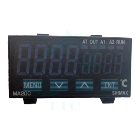
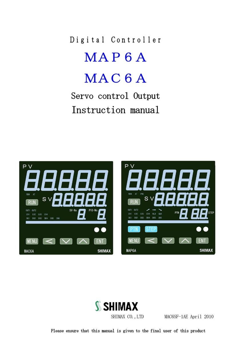
Shimax MAC6A User manual

DigitalController
MAC6A/
MAP6A
Instructionmanual
Please ensure that this manual is given to the final user of this product.
MAP6F-1EE March 2017
Thank you forpurchasing SHIMAX products.
Please check that the delivered Item is the item you ordered. Read this instruction manual
thoroughly and understand its contents before using this product.

1
Contents
1. Preface........................................................................................................................................................................ 2
2. Matters regardingsafety.............................................................................................................................................. 2
3. Introductions .............................................................................................................................................................. 4
3-1. Check beforeuse .................................................................................................................................................. 4
3-2. Order codetable .................................................................................................................................................. 5
4. Installation andWiring................................................................................................................................................. 6
4-1. Installation(Environmentalconditions).................................................................................................................... 6
4-2. Mounting............................................................................................................................................................. 6
4-3. External Dimensions and Panel Cutout................................................................................................................ 7
4-4. Terminal arrangement........................................................................................................................................... 9
4-5. Terminal arrangementtable................................................................................................................................. 10
4-6. Rear terminal arrangementdiagram ..................................................................................................................... 10
5. Names and Functionsof Parts onFront Panel .............................................................................................................. 11
5-1. Explanation of eachfunctions ............................................................................................................................ 12
6. Description ofscreens............................................................................................................................................... 15
6-1. How to move to another screen ......................................................................................................................... 15
6-2. Settingmethod ................................................................................................................................................... 17
6-3. Power ONsequence............................................................................................................................................ 17
6-4. PROG(programcontrol)settingscreens............................................................................................................... 27
6-4-1. Program patterncommonsettingscreen .................................................................................................... 28
6-4-2. Each program pattern setting screen............................................................................................................ 30
6-4-3. Each program stepsetting........................................................................................................................... 33
6-5. FIX (constant value control) setting screens.......................................................................................................... 38
6-5-1. Explanation of Ramp &Soak function ......................................................................................................... 39
6-6. Modesetting ...................................................................................................................................................... 46
6-6-1. Mode1 System setting................................................................................................................................. 46
6-6-2. Mode2 PV setting screen............................................................................................................................ 49
6-6-3. Mode3 Out1setting.................................................................................................................................... 52
6-6-4. Mode4 Out2 setting ................................................................................................................................... 59
6-6-5. Mode5 Zone PID setting screen................................................................................................................... 62
6-6-6. Mode6 Event1~4setting............................................................................................................................ 65
6-6-7. Mode7 DO setting...................................................................................................................................... 67
6-6-8. Mode8 DIsetting......................................................................................................................................... 69
6-6-9. Mode9 AO setting....................................................................................................................................... 71
6-6-10. Mode10 AIsetting..................................................................................................................................... 74
6-6-11. Mode11 CTsetting.................................................................................................................................... 77
6-6-12. Mode12Communicationsettingscreen..................................................................................................... 78
6-6-13. Mode13 Servo outsetting screen ............................................................................................................. 78
6-6-14. Mode14 PV SV multipoints compensationsettingscreen.......................................................................... 80
7. SupplementaryExplanationofFunction.................................................................................................................... 81
7-1. Auto returnfunction.......................................................................................................................................... 81
7-2. Outputsoftstartfunction...................................................................................................................................... 81
7-3. Event selection alarm operation figure............................................................................................................. 81
7-4. AT (AutoTuning) ................................................................................................................................................. 82
8. Trouble Shooting ...................................................................................................................................................... 83
8-1. Cause and treatment of main defects .............................................................................................................. 83
8-2. Causeand treatmentof error display .................................................................................................................... 83
9. Generalspecification .................................................................................................................................................. 84

2
1. Preface
This instruction manual is intended for those who will be involved in wiring, installation, operation and routine
maintenance of the MAC6 and MAP6.
This manual describes the care, installation, wiring, function, and proper procedures regarding the operation of
MAC6 andMAP6.
Keep this manual on hand while using this device. Please follow the provided guidance.
2. Matters regarding safety
This mark indicates hazardous conditions that could cause damage to equipment and/or facilities. Exercise
extreme caution asindicated.
WARNING
This mark indicates hazardous conditions that could cause injury or death of personnel.
Exercise extreme caution asindicated.
CAUTION
This mark indicates hazardous conditions that could cause damage to equipment and/or facilities.
Exercise extreme caution asindicated.
"NOTE"
This mark indicates additional instructions and/ornotes.
WARNING
MAP6 is designed for controlling temperature, humidity, and other physical subjects in general industrial facilities.
It must not be used in any way that may adversely affect safety, health, or working conditions.
CAUTION
To avoid damage to the connected equipment, facilities or the product itself due to a fault of this instrument, safety
countermeasures must be taken before usage, such as proper installation of the fuse and the overheating
protection device. No warranty, expressed or implied, is valid in the case of usage without having implemented
proper safetycountermeasures.

3
CAUTION
●The mark on the plate affixed to the instrument on the terminal nameplate affixed to the case of your
instrument, the mark is printed. This is to warn you of the risk of electrical shock which may result if the
charger is touched while it is energized.
●The external power circuit connected to the power terminal of this instrument must have a means of
turning off the power, such as a switch or breaker. Install the switch or breaker adjacent to the instrument in a
position which allows it to be operated with ease, and with an indication that it is a means of turning off the
power. Use a switch or breaker, which meets the requirements of IEC127.
●Fuse
Since the instrument does not have a built-in fuse, do not forget to install a fuse in the power circuit to be
connected to the power terminal. The fuse should be positioned between the switch or breaker and the instrument
and should be attached to the L side of the power terminal.
Fuse Rating: 250V AC 0.5A medium lagged or lagged type.
Use a fuse which meets the requirements of IEC127.
●Load voltage/current to be connected to the output terminal and the alarm terminal should be within the
rated range. Otherwise, the temperature will rise and shorten the life of the product and/or result in problems with
the product.
●Voltage/current that differs from input specification should not be connected to the input terminal. It may
shorten the life of the product and/or result in problems with the product.
●Input, DI, AI, CT, and FB terminals are not insulated. When use a grounding-type sensor, please do not ground
with those terminals.
●A signal wire's common mode voltage to ground (signal wires other than contact output including power
supply and event) should be less than 30V rms, 42.4V peak, and 60 VDC.
●All the wires for the interior distribution, except for communication and contact output (including power supply
and event), should be less than 30m in length. When the wire's length is 30m or more, or in the case of
outdoor wiring, the suitable measure against a lightning surge is required.
●EMC standard (IEC61326) classifies MAP6 into Class A apparatus. Electromagnetic interference may occur
when MAP6 is used at a business district or in the home. Please use after taking sufficient measures.
●There is a ventilation hole for radiation. Please make sure that the metal won't enter from this hole. It
may be occur abreakdown and fire.
●Do not block the draft hole or allow dust or the like to stick to it. A rise in temperature or insulation
failure may result in a reduction of the life of the product and/or problems with it or may cause a fire.
●It should be noted that repeated tolerance tests against voltage, noise, surge, etc. may lead to deterioration
of the instrument.
●Users are prohibited from remodeling the product or abnormal use thereof.

4
3. Introductions
3-1. Check beforeuse
Before using MAP6, please check the model code, the exterior appearance and accessories. Also make
sure that there are no errors, impairs and shortages.
Confirmation ofmodel code
Check that the product you ordered is being delivered properly. Check the model code of the main body case
against the following code table.
Check ofaccessories
CAUTION
Handling Instruction
●Do not operate the keys on the front panel with a hard or sharply pointed object. Operate the keys only by
softly touching them with fingertips.
●When cleaning the instrument, wipe it softly with a dry cloth. Never use solvents such as thinner.
NOTE : Please contact our agencies or business offices if you have any problem.
We welcome any kind of inquiry such as defect of the product, shortage of accessory and so on.

5
3-2. Order code table
Item
Code
Specifications
Series
MAP6A-
96 x 96 size 5 digit display programmable digital controller
Series
MAC6A-
96 x 96 size 5 digit display digital controller
Input
M
Full multi TC, RTD, mV, V, mA ※1
Control Output 1
C
Contact 1a 240V AC 2A (Resistance load)
S
Voltage pulse (SSR Drive Voltage) 12V DC max20mA
I
Current 4-20mA DC Load resistance max500Ω
V
Voltage 0-10V DC Load current max2mA
Y
Control motor (Servo control Output)Contact 1C 240V AC 2A
※2
X
Control motor (Servo control Output)SSR240V AC 2A
Power supply
F-
90-264V AC 50/60Hz
Event Output
E
Even Output 3 points (EV1-3) Contact 1a 240V AC 1A (Resistance load)
Control Output 2
N-
None
C-
Contact 1a 240V AC 2A(Resistance Load)
※2
S-
Voltage pulse 12V DC max20mA
I-
Current 4-20mA DC max500Ω
V-
Voltage 0-10V DC max2mA
Event Output
E-
Event output 1point (EV4) 240V AC 2A
(Resistance load)
DI (External operation input)
D
7 Points (DI1-7) 5V DC 0.5mA
DO-Ⅰ(External operation output Ⅰ)
N
None
J
3 Points(DO1-3) 24V DC 20mA
DO-Ⅱ(External operation output Ⅱ)
CT(Current sensor input)
FB(Feedback input)
N
None
J
DO-Ⅱ3 Points (DO4-6) 24V DC 20mA
H
CT 2 Points 50.0A
P
FB potentiometer input 3 wire 100Ω~2kΩ
AI(External analogue input)
N
None
I
Current 4-20mA DC
(Reception resistance100Ω)
V
Voltage 0-10V DC
(Input resistance about 500kΩ)
AO(External analogue output)
N
None
T
Current 4-20mA DC
Load resistance max300Ω
V
Voltage 0-10V DC max2mA
Communication
N
None
R
RS-485
W
RS-232C
1When using by current input, shunt resistance of option parts or same as items (less than 0.05% of 100 Ω) is needed.
2When Motor control Y or X installed, Out2 and EV4 cannot install.

6
4. Installation and Wiring
4-1. Installation (Environmental conditions)
CAUTION
This instrument should not be used in any of the places mentioned below. Selection of these places may result in
trouble with the instrument, damage to it or even a fire.
●Where flammable gas, corrosive gas, oil mist and particles generated.
●Where the temperature is below –10℃ or above 50℃.
●Where the relative humidity is above 90% RH or below the dew point.
●Where highly intense vibration or impact is generated or transferred.
●Near high voltage power lines or where inductive interference can affect the operation of the instrument.
●Where undergo influence of the equipment which generates a high frequency.
●Where the instrument is exposed to dew drops or direct sunlight.
●Where the height more than 2000m.
Note
The environmental conditions belong to the installation category II of IEC664 and the degree of
pollution is II.
4-2. Mounting
●Cut a hole for mounting the controller in the panel by referring to the cutout drawing.
●The panel thickness should be 1.2 to 3.2 mm. (It can be mounted up to 20mm of thickness using attachment)
●MAP6 has pawls of fixing, just press it from the front of the panel.
Note
MAP6 is designed to be mounted on a panel. Do not use it without mounting on the panel.

7
4-3. External Dimensions and Panel Cutout
External dimension (Unit: mm)
Panel cutout (Unit: mm)
Note:
Proximity attachment by a single hole is possible only in the case of horizontal direction. When an apparatus that
was attached in vertical direction is removed, a dedicated detachment tool is required.

8
4-4. Wiring
WARNING
●When wiring, make sure to disconnect the power supply. Otherwise an electric shock may result.
●After wiring, do not touch terminals or other charged elements while it is energized. Otherwise an
electric shock may result.
●After wiring, make sure the wiring are correct.
●Make sure that wiring operation is properly done in line with a terminal wire diagram.
●The press-fit terminal must fit an M3.0 screw and have a width of 6 mm or smaller. (Clamp receiving
torque: 0.5 to 0.6Nm)
●For wiring for power supply, use a 600V vinyl insulated wire or cable which is 1mm2or larger in section
or a wire or cable of equivalent for higher performance.
●For Thermocouple input use compensation wire compatible with the type of thermocouple.
●For RTD input the resistance of single lead wire have to be 10Ωor less, and the three wire have to
have same resistance.
●The input signal wire must not be accommodated with a high-voltage power cable in the same wiring
conduit or duct.
●Shielded wire (one-point grounding) is effective to avoid electrostatic induction noise.
●Twisting the input wires at short and equal intervals is an effective way to avoid magnetic induction
noise.

9
4-5. Terminal arrangement
Note: If input type is thermocouple or voltage, errors may occur when terminal 11 and terminal 12
terminal are short-circuited

10
4-6. Terminal arrangement table
No.
Symbol
Function
1
COM
DI input
2
DI1
3
DI2
4
DI3
5
DI4
6
DI5
7
DI6
8
DI7
9
+
Voltage(V) or Current
(mA) Input
11
-
10
+
Thermo couple or Voltage(mV)
Input
11
-
10
A
Resistance bulb input
11
B
12
b
13
L
Power supply 90~264V AC
14
N
15
COM
EV output
16
EV1
17
EV2
18
EV3
19
+
Output 1
20
-
21
+
Output 2/EV output(EV4)
22
-
No.
Symbol
Function
20
CW
Control motor driveoutput
21
COM
22
CCW
23
+
AO Output
24
-
25
COM
DO Output (DO1-3, DO4-6)
26
DO1
27
DO2
28
DO3
29
DO4
30
DO5
31
DO6
29
CW
Feedback potentiometer input
30
COM
31
CCW
29
COM
CT Input
30
CT1
31
CT2
32
+
AI input
33
-
34
SG
Communication RS 485
35
+
36
-
34
SG
Communication RS232C
35
TXD
36
RXD
4-7. Rear terminal arrangement diagram
1
COM
25
COM
13
L
2
DI1
26
DO1
14
N
3
DI2
27
DO2
15
EV-COM
4
DI3
28
DO3
16
EV1
5
DI4
29
DO4
COM
CW
17
EV2
6
DI5
30
DO5
CT1
18
EV3
7
DI6
31
DO6
CT2
CCW
19
Out1 +
8
DI7
32
AI +
20
Out1 -
CW
9
+
33
AI -
21
Out2 EV4+
COM
10
-
34
SG
SG
22
Out2 EV4 -
CCW
11
+
35
+
Txd
23
AO +
12
-
36
-
Rxd
24
AO -

11
⑤
⑥
5. Names and Functions of Parts on Front Panel
MAP6A
①
MAC6A
②
⑦
④
③
⑧

12
5-1. Explanation of eachfunctions
①Display of measured value (PV) (red)
Measured value (PV) and type of setting is displayed on each setting screen.
②Display of target value (SV) (green)
Target value and set value are displayed on each setting screen.
③Pattern No, Display (Green) (PID No, on MAC6)
Execution pattern No, (1-8) is displayed at program operation.
Execution SV No, is displayed at FIX operation.
④Step No, display (Yellow) (SV No, on MAC6)
Execution step No, is displayed (1- 96) at program operation.
Execution PID No, is displayed at FIX operation.
⑤Status LED Display
RUN : Light on at RUN Operation, Blinking at Manual operation.
AT : If AT is chosen in ON or external control input (DI), blinks during AT execution. Lights up when
AT is on standby, and Off with AT automatic termination or release.
PRG : On at the time of program control's standby or flat part control. Off at the time of FIX control
selection.
OUT1 : At the time of a contact or a voltage pulse output, On with ON and Off with OFF. At the time
Current Output or a Voltage Output, OFF with 0% power output, and ON with 100% power. And blinks
at intermediate ratio.
OUT2 : Same as Output1
EV1:ON at the allotted event output turns to ON
EV2~EV4:Same as EV 1
DO1:ON at the allotted event (DO) output turns to ON
DO2~DO6:Same as DO1
GUA(Guarantee soak):ON at GUA function execution.
During program operation, the SV value on program step proceed to flat step from ramp step, the PV
value some time delay from the SV value and the flat step become shorter than the step. This
function avoid and assuring the time of flat step.
HLD:ON at Hold function execution
(UP step):ON at UP step execution
(FLAT step):ON at FLAT step execution
(DOWN step):ON at DOWN step execution
⑥Bar graph display (20 Dot LED)
Bar graph displayed Output value, Valve position, progress of the program operation by 0% to 100%.
(5% per dot)

13
⑦Key-switch section
(RUN)KEY:
Press for 3 seconds at STBY (control stop), then FIX or PROG control starts. Press for 3 seconds
while FIX or PROG is in operation, then control is stopped.
(MENU)KEY:
Press this key to move onto the next screen among the screens.
en of FIX or PROG, then it jumps
on the screen of operation mode 2, then it jumps to the screen of operation Mode 1.
(Shift) key:Move the digit which set the value
The digit can be changed are blinked.
(Down) key:
continuously, the value as well consecutively decreases.
A decimal point of the smallest digit blinks at this time.
(Up) key :By
pressing continuously, the value consecutively increases. A decimal point of the smallest digit blinks
at this time.
MODE1 MODE2 MODE3 MODE4 MODE14
-8 from FIX mode lead screen
SV№1 FIX SV№ 2 SV№8
-8 from Program mode lead screen.
Pattern 1Pattern 2Pattern 8Pattern common setting

14
.1-96 from Program step lead screen.
Pattern1Step1Pattern1Step2Pattern1 Step15 Pattern1 Step96
key
The setting data changed on each screen is determined. (The decimal point of the minimum digit is
also lighted off).
Press the key for 3 seconds on the Mode 1 screen, then it shifts to Mode 2 screen.
Press three seconds on the monitor screen during RUN operation it shifts between Manual output and
automatic output.
Push at FIX-PROG and each mode screens' lead screen, then shifts to setting screen.
(Pattern) key (MAP6 only)
At a reset (RST) increment pattern No, on the basic screen
Press at the lead screen on the step setting screen, it sift to lead screen on the Program pattern
setting screen.
(Step) Key (MAP6 only)
Shift to Step1 lead screen of Pattern setting screen by pressing at PROG pattern setting lead screen.
Press one second on the step setting screen, it shift to next step.
1s 1s
Pattern 1 Step 1 Pattern 1 Step 2 Step 96 Return to Step1
⑧Infrared-ray communication port.
It can be communicated with MAP6 by USB adaptor and infrared-ray communication port. USB Adaptor
available on Optional parts.
Details refer to communication instruction Manual.

15
6. Description of screens
6-1. How to move to another screen
Basic screen Program control lead screen or FIX control lead screen
3sec
or
3 sec
Press the key for three seconds on a basic screen, then it shifts to the lead screen of (program control)
setting screens. (constant value control) setting screens, or to the lead screen of (constant value
control) settingscreens.
Press the key for 3 seconds on or the lead screen of setting screens, then it shifts to the
basic screen..The shift to is possible when the program option is selected at Mode2 .
The shift to is possible when the is selected at mode 2.
Basicscreen
3sec
MODE 1MODE 2MODE 3 MODE 14
Each settingscreen
Every time you press the key on a basic screen, it shifts to each screen of the basic screens.
Press the key for 3 seconds on a basic screen, then it shifts to the lead screen of mode 1 screens. Press
the key on the lead screen of mode 1 screens , then it further advances to mode 2, and mode 3.
(Notes: No corresponding if option is not found)
Press the key on the lead screen of mode 1 screens , then it further advances to mode 14, and mode13.
(Notes: No corresponding if option is not found)
Press the key for 3 seconds on the lead screen of mode 1~14 screens, then it shifts to the basic screen.
Press the key on the lead screen of mode 1~14 screens, then it shifts to the first setting screen of each
screens.

16
Press the key on the first setting screen of each screens, then it shifts to the next screen. Every time you
press the key, it shifts to the next setting screen.

17
6-2. Setting method
To change settings, display an appropriate screen and
On the output monitor screen of basic screens, you can change the control output from "Automatic" to
"manual", and save its change of setting. Display the outp
seconds to shift from Automatic to Manual.
Press
Automatic⇔Manual switchover does not work while STBY<RST> and AT are in operation.
In the case of two-output type, the switchover between automatic and manual is operatable through output 1
and output 2. The setting is altered simultaneously.
Output Monitor Output Monitor Output Monitor
or
3sec
Automatic screen RUN ON Manual RUN blinks Manual RUN blinks
6-3. Power ON sequence
At power-on, the display section shows each screen of initial screens for one second , then moves on to the basic
screen.
All LED ON
LED Test
Input Range
Measuring range
About 1sec
About 1sec
About 1sec
Output 1 Output 2 Return to Basicscreen
About 1sec About 1sec

18
6-4
Explanation of each basicscreen
Basicscreen
Executed SV
Initial value Sensor input : 0
Linear input : Lower limit of scaring
Setting range Sensor input : Within measuring range
Linear input With in scaring range
Within SV limiterbesides
Targeted value (PV) is displayed on the upper row as 5-digit, and target value (SV) is
displayed on the lower row also as 5-digit.
(Notes: hereinafter, measured value and targeted value are referred to as"PV" and"SV")
At the time of FIX, execution SV is displayed and change of setting is possible.
PROG's SV is just displayed, and change of setting is impossible.
During AT execuiting and Key lock level 2-4 are set, setting is impossible
At the time during AT and key lock level 2-4 is set, change of setting impossible.
Execution Program No. can be changed by pressing at the RST in Program.
When no key operation 3 minutes or more, screen will be shifted to basic screen or the
screen of DI super keylock.
When measuring range, unit and scaling value changed, parameter will be initialized.
Action Mode 1 Action Mode 2
3 sec
3 sec
Initial value :(Reset)
Setting range:Control stop (Output Off)
(RUN)conduct of control operation
Initial value:
Setting range:,
During no operation the display will be (Program) or (FIX).
Choose key and decided by key then Monitor LED's RUN lights up to start control operation.
Choose ( )by key, Decide by key, Then Monitor LED's RUN lights
off
and becomes control stop [Output OFF (0%)] conducting.
Priority is given to DI function, when RUN is allotted to external control input. DI. Key
operation cannot be performed unless allotment is canceled.

19
Auto :
Manual:
Press key for 3 seconds, then it shifts to Action mode2 screen, when the program
control option is added on this screen, FIX (constant value control) ←→PROG
(program control) switchover is possible choose(Choose a program, then Monitor LED's
PRG lights up.
Press key for 3seconds then it shift to Action mode 1.
Priority is given to DI function ,when PROG is allotted to external control input. DI. Key
operation cannot be performed unless allotment is canceled.
Press key then it shift to Output 1 monitor screen.
When measuring range, a unit, scaling, and output characteristics are changed, parameter
will be initialized and ( ) is display.
Output1 monitorscreen
Manual output setting range : 0.0-100.0% (within output limiter)
At the time of automatic output, monitor display only.
Refer to automatic ⇔ manual switch over, and setting method at the time of manual
operation.
A manual output is canceled when an operation mode is made into (
).
When a power source is intercepted and re-switched on, it returns to the condition
just beforeintercepting.
When is allotted to DI, DI is given priority. Automatic ⇔ manual
switchover is not performed with key operation, and only the output value at the time
of manual operation can be changed.
During AT executing or Key lock level 3-4 are set, setting is impossible
Output2 monitoringscreen
Contents are the same with that of an output 1
Output 2 monitoring screen displays only when output 2 option is added.
CT1monitor
Display range:0.0~55.0A
Displays at the time of CT input option addition, and the current value detected by
CT Sensor is displayed.
Upper Display: PV value
Middle Display: Currentvalue
Lower Display: Detected CT sensor (CT1)
Other manuals for MAC6A
1
This manual suits for next models
1
Table of contents
Other Shimax Controllers manuals
Popular Controllers manuals by other brands
IEI Technology
IEI Technology VWBOX-E133 user manual
Fbt
Fbt DLM26 user manual
Agilent Technologies
Agilent Technologies TwisTorr 305 FS Series user manual
Carson
Carson DRAGSTER PRIME SHOOTER SPORT SL 6T instruction manual
Wintriss
Wintriss SmartPAC PRO Integration manual
RF Mogul
RF Mogul DataSAT ACU-2 Operation manual

