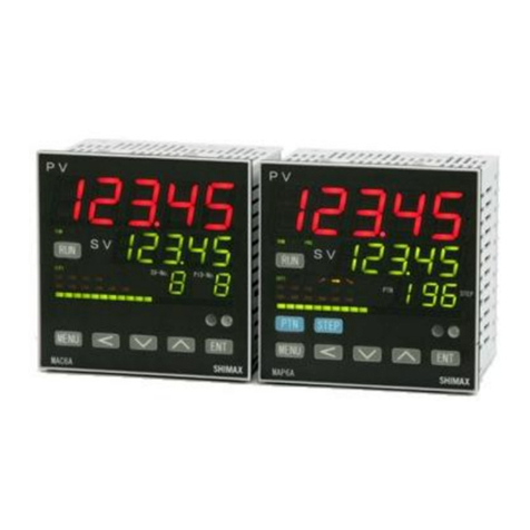
Shimax MA20C User manual

1
「Notice」
Please ensure thatthis manualis giventothefinal userofthe instrument.
Preface
This instructionmanualis meant forthose whowill beinvolved inwiring,
installation,operationandroutinemaintenanceoftheMA20C.
This manualdescribesthe care,installation,wiring,function,and properprocedures
regardingthe operationofMA20C.Keep this manual on hand whileusing thisdevice.
Followtheguidanceprovidedherein.
1.Mattersregardingsafety
Formatters regardingsafety,potentialdamagetoequipmentand/orfacilitiesandadditional
instructions areindicatedas follows.
◎Thisheadingindicateshazardous conditionsthatcould causeinjuryordeathofpersonnel.
Exerciseextremecautionasindicated.
「WARNING」
◎Thisheadingindicateshazardous conditionsthatcouldcausedamagetoequipmentand/or
facilities.Exerciseextremecautionasindicated.
「CAUTION」
◎Thisheadingindicates additional instructions and/ornotes
「NOTE」
「WARNING」
MA20C is designed for controllingtemperature, humidity,andotherphysicalsubjects.
It mustnot be usedin any waythat may adversely affectsafety,orworking conditions.
「CAUTION」
To avoiddamageto the connectedequipment,facilitiesortheproductitselfdue to afaultof
theproduct,safety countermeasuresmustbetakenbeforeusage,such as proper installation
ofthefuseand theoverheating protectiondevice.Nowarranty,expressed or implied,isvalid
inthecaseof usagewithout havingimplementedpropersafetycounter measures.
「CAUTION」
●The mark ontheplateaffixedto theinstrument:
Ontheterminalnameplateaffixedtothecaseofyourinstrument,the markisprinted.
Thisistowarmyouoftheriskofelectricalshockwhichmayresultifthechargeristouchedwhileitisenergized.
●Theexternalpowercircuit connectedtothepowerterminalofthisinstrument musthave a
meansofturningoffthepower,suchasaswitchorbreaker.
Install theswitchorbreaker adjacenttothe instrument in aposition which allows itto be
operatedwithease,andwithan indicationthatitisameansofturningoffthepower.
●Fuse:
Sincetheinstrumentdoesnothaveabuilt-infuse,donotforgettoinstallafuseinthepower
circuittobeconnectedtothepowerterminal.Thefuseshouldbepositionedbetweentheswitch
orbreakerandtheinstrumentandshouldbeattachedtotheLsideofthepowerterminal.
FuseRating: 250VAC0.5A/mediumlaggedorlaggedtype.
Useafuse,whichmeets therequirementsofIEC127.
●Loadvoltage/currenttobeconnectedtotheoutput terminal andthealarmterminal
shouldbewithin the rated range.Otherwise,thetemperaturewillriseand reduce thelife
oftheproductand/orresultin problemswiththeproduct.
●Voltagedifferentfromthatoftheinputspecificationshouldnotbeconnectedtotheinputterminal.
Itmayreducethelifeoftheproductand/orresultinproblemswiththeproduct.
●Input,voltagepulseoutput,andcurrentoutputarenotisolatedelectricallyfrominsidecircuits.
Whengroundthermocouplesareused,thecontroloutputterminalshouldnotbeconnectedtoearth.
(Ifconnected,wraparound causes errors.)
●This instrument is provided with a vent for heat discharge. Take care to prevent metal or other
foreignmatterfrom obstructing the vent. Failure to do so may result in problems with the
productandmayevenresultinfire.
「CAUTION」
●This instrument has basic insulation between the power supply and the secondary
circuit.If accessible Safety Extra Low Voltage (SELV) circuits are to be connected to
Signalinput/output terminals (Input, Output(SSR, Current, Voltage), DI, CT, Analog
output, Communication, and other secondary circuit), ensure to provide abasic insulation
between the SELV circuits andthese terminals (For example, use transformer which has a
basicinsulation or higher degree of insulation).Thebasic insulation requires aclearanceat
least1.5mmand acreepageofatleast3.0mm.
●Donotblocktheventorallowdusttoaccumulate.Theriseintemperatureorinsulationfailurecaused
byblockingtheventmayresultinreducingthelifeoftheproductand/orproblemswiththeproduct.
●Repeatedtolerancetestsagainstvoltage,noise,surge,etc.mayleadtodeteriorationoftheinstrument.
●No modificationorirregularusageisallowed.
2.Introduction
2-1.Check beforeuse
Beforeusingthisproduct,youarerequiredtocheckthemodelcode,theexternalviewoftheproduct
andtheaccessoriestomakesurethatthereisnoerror,damage,orshortageofdelivereditems.
Confirmation of model code: Check the model codes on the case of the product to ascertain
that thedelivereditemiswhatyouorderedby referring tothefollowing codetable.
Exampleofmodel code
MA20 C- MCF- 2N- 0
123 4 5 6 7
Item
1.Series MA20 2.Classification C--:controller 3.Iinput M:multi V:voltage I:current
4.Control output C:contact S:voltagepulse I:current(4~20mA)V;(0~10V)
5.PowerSupply F-:90 –264VAC L-:21.6–26.4V DC/AC
6.Option 0N-:without 1N-:alarmoutput1point 2N-:alarmoutput2points
0D-:externalcontrolinput(DI)2points
1D-: alarmoutput1point+externalcontrolinput(DI)2 points
0T-:analogoutput(4~20mA) 1T-:alarmoutput1point+analogoutput
2T-;alarmoutput2point+analogoutput
0R-:communicationofRS-485
1R-:alarmoutput1point+communicationofRS-485
1B-: alarmoutput1pointwithbuzzer 2B-:alarmoutput2pointwithbuzzer
7.Remarks 0:without 9:with
Checkofaccessories
Instructionmanual: 1set
「NOTE」:Contactourrepresentativeorourlocalofficeconcerninganyproblems
withtheproduct andaccessories,orforanyinquiry.
2-2.Caution foruse
(1)Avoidoperatingthefrontpanelkeyswithhardorsharpobjects.
Touchthekeys lightlywithfingertips.
(2)Toclean,wipegentlywith adry cloth.Avoidusingsolventssuch asthinner.
3.Installation andwiring
3-1.Installation site (environmental conditions)
「CAUTION」
Donotusethisinstrumentunderthefollowingconditions.
Otherwise,thelikelihood of fire and/orotherdangeroussituations are considerable.
(1) Where flammablegas, corrosivegas,oil mistordustthat can deteriorate.
electrical insulation is generated or is abundant.
(2) Wherethetemperatureisbelow -10℃orabove60℃
(3) Wherethehumidityisover90%RHorwherecondensationoccurs.
(4) Wherehighlyintensevibrationorimpactisgeneratedorcanaffecttheoperationoftheproduct.
(5) Nearhighvoltagepowerlinesorwhereinductiveinterferencecanaffecttheoperationoftheproduct.
(6) Wheretherearedewdropsor directsunlight.
(7) Wherethealtitudeisabove2,000m.
「NOTE」:Theenvironmentalconditionsherecomplywith theinstallation
categoryⅡandthepollutiondegree2setbyIEC664.
3-2. Mounting.
(1) Machinethemounting holeby referringtothepanel-cutillustrationinSection3-3.
(2) Applicablethicknessofthemountingpanelis1.2~3.2mm.(Withmetalfittings,itcanbe1.0~4.0mm.)
(3) Asthisproductprovides mountingfixture,inserttheproduct intothepanel.
「NOTE」:MA20C is apanelset-up type. Pleaseuse theproductaftersetting up to thepanel.
MA20CF-1DE August.2020
MA20C
Digital controller
Instruction manual
Thankyou forpurchasing SHIMAXproducts.Pleasecheck that thedelivered
Productistheitemyouordered.Pleasedonotbeginoperatingthisproductuntil
Youhavereadthisinstructionmanualthoroughly andunderstand itscontents.

2
3-3.External dimensionandpanel cutout
MA20C externaldimensions(unit:mm)
Packing
2
5
Panel(Thickness of applicable panel 1.2~3.2mm
1~4mm with metal fittings)
10 2
22
10 0
SHIMAX
MA20C
AT OUT A1 A2 RUN
MENU
ENT
48
24
MA20Cpanelcutout (unit:mm)
Individual Installation foroneunit and morethanone unit closely mounted each in onehole
22.2+0. 3
-0
45 .0
+0.5
-0
Refer to Installation Space Table shown below
Refer to Installation Space Table shown below
Min.InstallationSpaceAccordingtoThickness of thePanel
Thicknessof InstallationSpace Thicknessof Installation Space InstallationSpace
Panel (Vertical) Panel (Vertical) (Horizontal)
1.0 25.0 2.3 24.0 More than 48.0 asfor
1.2 25.0 2.8 24.0 horizontaldirection
1.6 24.4 3.2 24.0 More than66.0with
2.0 24.0 metalfittings
Horizontally ConsecutiveInstallationinOne Hole(Max.6units)Non-application of IP66
22.2+0.3
-0
W=(48 ×n-3)
+0.5
-0
n:
Number of Installed Units
(2≦n≦6)
n 2 3 4 5 6
W 93 141 189 237 285
Vertically ConsecutiveInstallationinOne Hole(Max.6units)Non-applicationofIP66
45.0
+0.5
-0
H=(24 ×n-1.8)+0.3
-0
n:Number of Installed Units(2≦n≦6)
n 2 3 4 5 6
H 46.2 70.2 94.2 118.2 142.2
「NOTE」:Metal fittingsareneeded foreachunit in caseofvertically consecutive
installation in onehole.
ExternalView ofInstallationwith Metalfittings
62.8
44.8
3-4.Wiring
「WARNING」
◎Toprevent electricalshock,turnoffelectricityduringwiringoperation.
◎Avoidtouchingthewiredterminalsandchargerswhilesupplyingpower.
(1) Wiringoperationshouldbedoneaccordingtotheinstructionoftheterminalarrangementplaninsection3-5
(2) Incaseofthermocoupleinput,choosethecompensationwiresuitabletothethermocoupletype.
(3)In case of R.T.D. input, leads should be less than 5Ωin resistance and three leads
should have the same resistance.
(4) Inputsignallineshouldnotbelaidinthesamewireorductasthatofthehighvoltageline.
(5) Shieldwiring(singlepointgrounding)is effectiveforstaticinduction noise.
(6) Shortintervaltwistedpairwireforinputsignaliseffectiveforelectromagneticinductionnoise.
(7) Whenwiring,theconnectorterminal canberemovableifitispulled right andleft
one aftertheotherasshowninthedrawingbellow.
Board
⇔
Attach/Detach
ConnectionTerminal
Case
(8) To avoid wiring slip and short circuit, use the suitable cable, insert it thoroughly, and
fastentheconnectionscrewstightlywith aminus driver.
Tightening torque: 0.2 ~ 0.25N•m (recommended performance)
0.3 N•m (guaranteed performance)
Connection
Length of Wire to be
Wire
AppropriateWire
0.12~1.25mm
2
(
StrandedWire
)
φ0.4~1.2mm(
Solid Wire
)
Minus Driver
RecommendedAdhesionTerminal
Type
AppropriateWire
(mm
2)
216-301 0.25
216-302 0.34
216-201 0.5
216-202 0.75
WAGO
Color Ferrules
Screw M2
peeled 5
~
7mm
3-5.Terminalarrangementplan
12
34
5689
Power supply Option
Control output
LN
90-264V
AC
12
LN
21.6-
26.4V
AC/DC
+-
34
34
Contact
+-
Voltage
pulse
+-
Current
4-20mA
+-
Current
4-20mA
56789
AlarmOutput
Analog Output
AL1
AL1
AlarmOutput
External control input
COM DI1 DI2
123410 11 12
56789
567
AlarmOutput
COM AL1 AL2
10 11 12
Input
11 12
11 12
+-
Current
A
BB
R.T.D.
+-
Thermocouple
Voltage
+
At the time of current input
Attached external resistance
250Ω
11 12
-
※
Terminal arrangement of
R.T.D.shouldbe
10:B,11:A,12:Binorder.
(DI)
56789
AL1
AlarmOutput
SG
+-
Communication
of RS-485
34
+-
Voltage
0-10V
「NOTE」:Wheninput typeis thermocoupleorvoltageashoot circuit between
10and12 terminalscausemeasurementerrors.

3
4.Descriptionoffront panel
4-1.Drawingandthenameofparts.
SHIMAX
MA20C
AT OUT A1 A2 RUN
MENU
ENT
①②
③
④
4-2.Descriptionofparts onthefrontpanel
①:Displaysection ofmeasuredvalue(PV) (red)
Measuredvalue(PV)andtypeofsettingoneachsettingscreenaredisplayed.
②:Displaysection of target value(SV) (yellow)
Targetvalue(SV)andsetvalueoneachsettingscreen aredisplayed.
③:Monitor LEDsection
(1) Controloutput monitorLED OUT (yellow)
Atthetimeofcontactorvoltagepulse output,LEDlights upwith outputON,
andturnsoffwithoutputOFF.Atthetimeofcurrentoutput,LEDturnsoff
with 0%output, lights up with 100% output, and blinks between 0% and 100%
accordingtoratio.
(2) Alarmoutput monitorLED A1,A2 (red)
LEDlightsupwhen assignedalarmoutputturnsON.
(3) Autotuning actionmonitor LED AT (yellow)
When ON is chosen on AT screen,or when AT is chosen in the external control
input (DI), AT starts operating and LED blinks, and turns off when AT is
cancelledorautomatically completed.
(4)RUN monitorLED RUN (yellow)
When RUN is chosen on actionmodescreen orinthe external control input (DI),
LED lights up and turns off with Stby. When Manual output is chosen on output
monitorscreenorintheexternal controlinput(DI),LEDblinks.
④:Key-switch section
(1) (MENU)key
Press keytomoveon tothenextscreenineachscreen.
Press key for three seconds on the basic screen and the screen jumps to the
lead screen of Mode1.Press MENU key forthree seconds on thelead screen of
each of Mode screens and thescreen jumpstothe basicscreen
(2) (DOWN) key
Onepressof keydecreasesthesetvaluebyone.Bypressing thekey,
thevaluecontinuesdecreasing.
Duringsetting,adotbesidetheleastdecimalplaceisblinking.
(3) (UP)key
One press of key increases the set value by one. By pressing the key, the
value continues increasing. During setting, adot beside the least decimal place is
blinking.
(4) (ENTRY) key
Press key to resister the setting changedby or key.(Adot besidethe
leastdecimalplacestopsblinking.)
Press key on the control output screen for three seconds to choose between
automaticoutputandmanualoutput.
Press key on thelead screen of each of Mode screens and the screen moves
toasettingscreen.
5.Descriptionofscreens
5-1.How to moveto another screen
Agroupofbasicscreens Mode 1~7 screens
Basicscreens LeadscreenofMode1 LeadscreenofMode2 Leadscreenof Mode7
3sec.
3sec.
Actionmodescreen Keylocksettingscreen PVbiassettingscreen
Press keyonthebasicscreentomovetoanotherbasicscreen.
Press keyonthebasicscreenforthreesecondstojumptotheleadscreenofMode1.
Press key on theleadscreen of Mode1 to moveto theleadscreen of Mode 2,Mode3in order. (Whenthereis no option assignedtoMode4~Mode7,itskips)
Press key on thelead screenof Mode1to moveto thelead screen of Mode 7,Mode6in order.(Whenthereis no option assignedtoMode4 ~Mode7,it skips)
Press keyontheleadscreenofMode1~7to movetothefirstsettingscreenofeachMode.
Press keyonthefirstsettingscreenofeachModetomovetothenextsettingscreen.
5-2.How to set
Tochangesettings,display anappropriatescreenand changethesetting(value orfunction)bypressing or key. Thenpress keytoresisterthesetting.Ontheoutputmonitorscreen
ofagroup ofbasicscreens,thetypeofcontroloutputcanbechosenfrom“automatic”or“manual”..Display theoutputmonitorscreen andpress key forthreesecondsto transfer from
automatictomanual.Thenbypressing or key, settings canbechanged.Inthis case, keydoesn’thavetobepressedtoresisterthesettings.Toshiftbackfrommanualtoautomatic,
press keyforthreesecondsaswell. (Note: Switchoverbetween automaticoutputand manualoutput cannotbedoneunless Key Lockis OFF orwhen STBYand AT areactive.)
Outputmonitorscreen Outputmonitorscreen Outputmonitorscreen
3sec. or
Screenofautomatic Screenofmanual Screenofmanual
RUNmonitorLEDlightsup RUNmonitorLED blinks RUNmonitorLEDblinks
5-3.Power-on andinitialscreen display
Atpower-on,thedisplaysectionshowsinitialscreenssuccessively foronesecond each,thenmovesontothebasicscreen.
《Power-on》
AllLEDlightsup Inputtype Lowerand higherlimitvalue Output type :Contact Basicscreen
oftheselectedmeasuring range :Voltagepulse :Current

4
5-4.Descriptionofscreens
(1)Agroupof basicscreens
Basicscreen
ExecutedSVinitial value: Sensorinput 0
Linearinput Lowerlimit ofscaringrange
Setting range:Sensorinput Within measuring range
keu Linearinput Withinscalingrange
Both of themshouldbe within SV limit range
Onthebasicscreen,the4-digit-numbersectionontheleftdisplaysmeasuring
value(PV)and the4-digit-numbersection on theright displays targetvalue(SV).
(Note:Measuring valueisshown as PV and target valueasSV.)
Action modescreen
Initialvalue: (Stand-by)
Settingrange: Outofoperation{OutputOFF(0%)}action
key Automaticormanual controloutput action
Choose“run”with key and resisteritwith key.LEDofRUNonthe
monitorlightsupwhileautomaticcontrol is active,andblinkswhilemanual
controlis active.
Choose“Stby”with keyandresisteritwith key.LEDofRUNonthe
monitorturns off and thecontrol stops({OutputOFF(0%)}.
IfRUNisassigned to externalcontrolinputDI(1or2),DItakesprecedence.
Unless the assignmentiscancelled,nokeyoperation is possible.
Whenmeasuringrange,unit,scalingoroutputspecificationsarechanged,the
settingisinitializedandgoesbackto“Stby”.
Output monitorscreen
Manualoutputsetting range:0 ~100% (withinoutput limit)
When automaticoutputis chosen,justthemonitor is displayed.
key When “automaticoutput”is chosen,thefourthplaceofthe4-digitnumber
displays .When“manualoutput”is chosen,thefourthplaceofthe
4-digitnumberdisplays .
RefertoSection5-2asforswitchoverbetweenautomaticandmanualand
settinginmanualoperation.
Whenactionmodeis“ ”,manualoutput is cancelled.
Whenthepoweris cut andthenturnsonagain,theoutputsettinggoes
backto theoutput actionjustbeforethepoweris cut.
When isassignedto DI(1or2),DItakesprecedence.
Theswitchoverbetweenautomaticandmanualcannotbedonebykey
operation.Onlyoutput value at thetimeofmanual operation canbe changed.
AT (AutoTuning)screen
Initialvalue:
key Settingrange: 、
WhenONischosen,ATisexecuted.WhenOFFis chosen,ATiscancelled.
When“stby”, “manualoutput”,or“P=OFF”is chosen,thereisno display.
WhenkeylockisnotOFForatthetimeofscale-over,AT cannotbeexecuted.
During AToperation,nokey operation canbedone except cancellation ofAT
andsetting of“stbyand“key lock”.
Exceptnormal completionofAT operation,time-over(200minutes),
scale-over,choiceof“stby”,orcancellationofATforcesAToperationtostop.
Note:Evenifoutputlimit issetat anyvalueotherthan0~100%,AT
ignoresthesetting and is executed eitherat0% or100%.
First SVsettingscreen
Initialvalue:Sensorinput 0
Linearinput lowerlimitofscaling range
Setting range:Sensorinput withinmeasuring range
key Linearinput within scalingrange
Bothofthemshouldbe within SVlimit range
WhenFirstSVistheexecutedone,thevalueisdisplayedon thebasicscreen.
When measuringrange,unit,or scaling rangeis changed the settingis initialized.
Second SVsettingscreen
Initial value:thesame as thoseof First SV
key Setting range:thesame as thoseof First SV
WhenSecond SVistheexecutedone,thevalueis displayed onthebasicscreen.
When measuringrange,unit,or scaling rangeis changed the settingis initialized.
Thisscreen isdisplayedwhenthesecond SVisassigned toDI(1or2).Whenthe
terminaloftheassignedDIisshorted,thesettingbecomesexecuted SV.
Third SV setting screen
Initial value:thesame as thoseof First SV
key Settingrange:thesame as thoseof First SV
WhenThirdSVistheexecutedone,thevalue isdisplayedonthebasicscreen.
When measuringrange,unit,or scaling rangeis changed the settingis initialized.
ThisscreenisdisplayedwhenthethirdSVisassigned toDI(1or2).Whenthe
terminaloftheassignedDIisshorted,thesettingbecomesexecuted SV.
Alarm1 operatingpoint settingscreen
Initialvalue:higherlimit absolutevaluewithin measuringrange
higherlimitofscaling range
Lowerlimit absolutevaluewithin measuringrange
Higherlimitdeviation 2000
key Lowerlimitdeviation -9999
Withindeviation 0
Beyonddeviation 2000
Control loop/disconnection 9999
Setting value:Higherlimit absolutevaluewithinmeasuring rangewithinscaling range
Lowerlimit absolutevaluewithinmeasuring rangewithinscaling range
Higherlimitdeviation ~unit
Lowerlimitdeviation ~unit
Withinhigherandlowerdeviation ~unit
Beyondhigherandlowerdeviation ~unit
Control loop/disconnection ~seconds
OperatingpointofthealarmtypeassignedtoAlarm1canbeset.
Whenthereisnoalarmoption,orwhen“AL1 ”is chosen,there isno display.
Eachdeviationalarmandcontrolloop/disconnectionalarmtakeeffect whenaction
modeis“ ” andwhen“automaticoutput”ischosen.
Each deviationalarmis PV deviationtotheexecuted SV
Control/disconnection alarm watchestimewhen PV isoutofproportional band.
AtthetimeofON-OFFoperation,it watchestimewhen PVisoutofdifferentialgap
Alarm2 operatingpoint settingscreen
Initialvalue,setting range,and otherconditions arethesameas
thoseofAlarm1.
key
Latching cancellationscreen
Initialvalue:
key Settingrange: cancellationofalarm1
cancellation ofalarm2
simultaneouscancellation of all thealarm
When ischosenonlatchingsettingscreen ofeachalarmmode,
numberand aredisplayed.Whenlatchingis“ ”,oncealarm
turnson,thealarmoutputcondition continues evenifalarmisOFF.
Onthisscreen,on-going alarmoutputcan becancelled.
When alarmisin latching condition,adot besidetheleastdecimalplaceblinks.
Theblinkingindicatesthatitispossibletocancelthealarmsetting.
When keyispressed,thealarmis cancelled andthe dotstops blinking.
However,the condition iswithin alarmoutput region,cancellation is impossible.
Back tothebasic screen
(2)Agroup of Mode 1screens
Lead screenofMode1
Thisscreenisdisplayedwhen keyispressed for3seconds
key onthebasicscreen.
Thereisnosettingon this screen.Press key and the screenwill shiftto
thefirst settingscreen,Key locksettingscreen.
Keylocksettingscreen
Initialvalue:
key Settingrange: 、 、 、
Onlytheexecuted SV(onthebasicscreen)and “keylock”canbechanged.
Only“keylock”canbechanged.
Only“keylock”can be changed,andthere is nodisplayof SVonthebasic
screen.
Note:Evenif“keylock”is setas1or2,manualoutputvaluecanbechanged.
SVlimitlowervaluesettingscreen
Initialvalue:lowerlimitofmeasuring range
key Settingrange:lowerlimitofmeasuring range~higherlimitof
measuring range-1
Lowerlimitoftargetvaluecanbeset.
LowervalueofSVlimittakesprecedenceoverhighervalue.Ifhighervalueisset
lowerthanthelowervalue, highervalueisautomatically set at 1higher thanthe
lowervalue.
SVlimithighervaluesettingscreen
Initialvalue:higherlimitofmeasuringrange
key Setting range:SVlimitlowervalue+1~higherlimitofmeasuringrange
Higherlimitoftargetvaluecanbeset.
Back to theleadscreenofMode1

5
(3)Agroupof Mode2screens
LeadscreenofMode2
Thisscreenis displayedwhen keyis pressedonthe lead
key screenofMode1,orwhen keyis pressedonthe lead screen
ofMode3. Thereisno settingonthisscreen.
Press key andthescreen will shifttothefirstsetting screen,PVbias
settingscreen.
PVbiassettingscreen
Initial value:0
key Settingrange:-200~200unit
Thissetting isused tocorrectsensor input errors,etc.
Controlis executedbasedonthecorrectedvalueifbiased.
PVfiltersettingscreen
Initialvalue:0
key Settingrange:0 ~100sec.
Thissettingisusedtoreducetheadverseeffectsincaseoflargeinput
changeandnoiseoverlapping.
This functionis notperformedif thesettingis0sec.
Measuringrangesettingscreen
Initialvalue:multi voltage/current
key Settingrange:5 –5accordingtoMeasuringrangecodetable
Measuring ragecanbesetbycombinationofinputtypeandmeasuring range.
Unitsettingscreen
Initialvalue:
key Settingrange: 、
Temperatureunitforsensorinput canbechosenbetween (℃)and ( ).
Thissettingisnotdisplayedwhenlinearinputischosen.
Inputscalinglowerlimitsettingscreen
Initialvalue: 0.0
key Settingrange: 1999~9989unit
Lowerlimitofscalingrangeat thetimeoflinearinput canbeset.
Inputscalinghigherlimitsettingscreen
Initialvalue: 100.0
key Settingrange: 1989~9999unit
Higherlimitofscalingrangeatthetimeoflinearinput canbeset.
NOTE:Ifthedifferencebetweenthelowerandhigherlimitsissetatless
than10oratmorethan10000,thehigherlimit,settingisautomatically
changedto+10or+10000.
Thehigherlimit cannotbesetatlessthan+10ormorethan+10000.
Inputscalingdecimalpointsettingscreen
Initialvalue:1stdecimalplace(0.0)
key Setting range:Nodecimalpoint ~3rddecimalplace (0.000)
Thedecimalplaceofscalingrangecanbeset.
NOTE:Inputscalingscreensbecomeamonitoratthetimeofsensorinput,
andthesettingcannotbechanged.
BacktotheleadscreenofMode2
(4)Agroup ofMode3screens
Lead screenofMode3
Thereisnosettingonthis screen.
key Press keyandthescreenwillshifttothefirstsettingscreen,
PVbiassettingscreen.
Proportional band (P)settingscreen
Initialvalue:3.0%
key Settingrange:OFF,0.1 ~999.9%
ThereisbasicallynoneedofsettingonthisscreenwhenATisexecuted.
WhenOFFis chosenonthis screen,theprocedure onthis screen switches to
ON-OFF(two-position)control.
Differentialgapsettingscreen
Initialvalue:5
key Settingrange:1~999unit
DifferentialgapatthetimeofON-OFFcontrolcanbeset.
Thisscreenis displayedwhen P=OFFis chosen on the
proportional band (P)setting screen.
Integral time (I)settingscreen
Initialvalue:120sec.
key Settingrange: OFF,1~6000sec.
Thereisbasically noneedofsettingonthisscreenwhenAT is executed.
Thisscreenisnotdisplayedat thetimeofON-OFFcontrol.
Derivativetime(D)settingscreen
Initialvalue:30sec.
key Settingrange: OFF,1~3600 sec.
ThereisbasicallynoneedofsettingonthisscreenwhenATisexecuted.
Thisscreenisnotdisplayedat thetimeofON-OFFcontrol.
Manualreset settingscreen
Initial value:0.0
key Settingrange:-50.0~50.0%
Offset correction at thetimeofI=OFF (Paction,PD action) canbemade.
ThisscreenisdisplayedwhenI=OFFischosen.
Outputlowerlimit settingscreen
Initialvalue: 0
key Setting range: 0~99%
Control output lower limit value can besetonthisscreen.
NOTE:AtthetimeofAT,Stby,andscale-over,theoutput limit
valueisignored.
Outputhigherlimitsettingscreen
Initialvalue:100
key Settingrange:outputlimitlowervalue+1 ~100%
Controloutputhigherlimitvaluecanbesetonthisscreen.
Outputproportional cycletimesettingscreen
Initialvalue:contactoutput 30 sec.
key voltage pulseoutput 3 sec.
Setting range: 1 ~ 120 sec.
Outputproportional cycletimecan be seton this screen.
Thisscreenisnotdisplayedwhen“controloutput”iscurrent.
Outputcharacteristicsettingscreen
Initialvalue:
key Setting range: 、
Controloutput characteristicscanbechosenbetween (heatingcharacteristic)
and (cooling characteristic).
Back totheleadscreenofMode3
(5)Agroup of Mode 4screens
Agroup ofMode4screensarealarmoptionsettingscreens.
When theoptionisnot added,thesescreensarenot displayed
Lead screen ofMode4
Thereisnosettingonthisscreen.
key Press key andthescreen willshifttothefirstsettingscreen
alarm1modesettingscreen.
Referto5-6.AlarmActionchart regarding actions.
Alarm1 mode settingscreen
Initialvalue:
key Setting range: accordingtoAlarmtype code table
Alarm typeto beassigned toAlarm1 can bechosenandset accordingto
thecodetable.
Foralarm1differential gap settingscreen
Alarmtypecodetable
Alarm code
Alarmtype
Alarmcode
Alarmtype
Notassigned
Lowerlimitdeviation
Higher limit absolutevalue
Within deviation
Lowerlimit absolutevalue
Beyond deviation
Overscale
Controlloop/disconnection
Higher limit deviation
When measuring range,unit,orscalingrangeischanged thesettingis initialized.

6
Alarm1 differential gapsettingscreen
Initialvalue: 5unit
key Settingrange:1~999unit
ON-OFFdifferentialgapofAlarm1canbesetonthisscreen.
Thisscreenisnot displayedwhenAlarm1 modeis , ,and .
When measuringrange,unit,scaling rangeorAlarm 1modeischanged,the
settingisinitialized.
Alarm1 stand-by actionsettingscreen
Initialvalue:
key Settingrange: 、 、
:nostand-byaction
:stand-by actiononlyatthetimeofpower-on
:stand-by action at thetimeof changeofeach alarm operatingpoint andchange
oftheexecuted SV by deviation alarmwarningwhenthe powerison.
ThisscreenisnotdisplayedwhenAlarm1modeis ,and .
Whenmeasuringrange,unit,scalingrangeorAlarm1 modeischanged,thesetting
isinitialized.
Alarm1 latching settingscreen
Initialvalue:
key Settingrange: 、
Whenlatchingissetas ,oncealarmoutputturnson,thealarmoutput
conditioncontinues evenifalarmturnsOFF.
ThisscreenisnotdisplayedwhenAlarm1 modeis .
When measuringrange,unit,scaling rangeorAlarm1 mode is changed,the
settingisinitialized
Alarm1 output characteristicsettingscreen
Initialvalue:
key Settingrange: 、
Alarm1outputcharacteristics canbechosen from :normalopen and
:normalclose.
ThisscreenisnotdisplayedwhenAlarm1 modeis .
NOTE:When ischosen,relayturnsONafter500msfrompower-on
andturns OFFin alarm region.
Alarm1 toneofbuzzersettingscreen
Initialvalue:
key Settingrange: ,1~32
Canbeset alarm1 toneofbuzzerfrom1to32.
Buzzeris notsoundedwhenthisscreen set .
When theoptionisnot added,thesescreensarenotdisplayed.
Thisscreen isnotdisplayedwhen Alarm1modeis .
Alarm1 soundtimeofbuzzersetting screen
Initialvalue:
key Settingrange:1~100sec.,
Canbeset alarm1 soundtimeofbuzzer.
Continuesoundofbuzzerbetween alarm1onactionwhen set .
When theoptionisnot added,thesescreensarenotdisplayed.
Thisscreen isnotdisplayedwhen Alarm1 toneofbuzzersetis .
Thisscreen isnotdisplayedwhen Alarm1modeis .
Alarm2 mode settingscreen
Initialvalue:
key Setting range: accordingtoAlarmtypecode table
AlarmtypetobeassignedtoAlarm2canbechosenandsetaccording
tothecodetable.
Whenmeasuringrange,unit,orscalingrangeischangedthesettingisinitialized.
Alarm2 differential gapsettingscreen
Initialvalue: 5unit
key Settingrange: 1~999unit
Thesame asthoseofAlarm1
Alarm2 stand-by actionsettingscreen
Initialvalue:
key Settingrange: 、 、
Thesame asthoseofAlarm1
ForAlarm2latchingsettingscreen
Alarm2 latching settingscreen
Initialvalue:
key Settingrange: 、
Thesame asthoseofAlarm1
Alarm2 output characteristic settingscreen
Initialvalue:
key Setting range: 、
Thesame asthoseofAlarm1
Alarm2 toneofbuzzersettingscreen
Initialvalue:
key Settingrange: ,1~32
Thesame asthoseofAlarm1
Alarm2 soundtimeofbuzzersetting screen
Initialvalue:
key Settingrange:1~100sec.,
Thesame asthoseofAlarm1
Back totheleadscreenofMode4
(6)Agroup of Mode 5screens
Agroup ofMode5screensareexternal controlinput(DI)optionsettingscreens.
Whentheoptionisnotadded,thesescreensarenotdisplayed.
DIinputiseitherno-voltcontactoropencollector.
Lead screen ofMode5
Thereisnosettingonthisscreen.
key Press keyandthescreenwillshifttothefirstsettingscreen,
DI1modesettingscreen.
DI1modesetting screen
Initial value:
key Settingrange: according to DI action code table
DIaction tobeassignedto DI1canbechosenandsetaccordingtothecodetable.
DI 2modesetting screen
Initial value:
key Settingrange: according to DI action code table
DIaction tobeassignedto DI2canbechosenandsetaccordingto thecodetable.
Back totheleadscreenofMode5
DIAction Code TableandConstraint Items
DIAction CodeTable
DICode Action type Input
Detection
Noassignment
SecondSV Level Executed SV=Second SVwithDI
terminals closed
ThirdSV Level ExecutedSV=ThirdSVwithDI
terminals closed
Controlrun Level RUN withDIterminals closed
STBYwith DIterminals open
ManualOutput Level Manual withDIterminals closed
AutomaticwithDIterminalsopen
Latching cancel Edge Latching cancellationwithleading edge
Autotuning Edge AT operationwithleading edge
SuperKey Lock Level SuperKeyLock with DI terminalsclosed
CancellationwithDIterminalsopen
・and actions aresettobeexecutedduringAToperation,thesettings
areexecutedwhenAToperationstops
・When and areassignedtoeachDIand whenbothofthemareset
tobeexecutedsimultaneously, istheexecutedSV.
・canbeexecutedatthetimeofRUN-automaticoutput operation.
・TocancelATinhalfwaywhile is assigned,chooseOFFonATscreen.
・ATiscancelledwhen“STBY”or“manualoutput”isexecuted.
・DIactionisstilleffectiveevenwhen“keylock”issetatotherthanOFF.
・ThesameactioncannotbeassignedtoDI1and DI2
・TheactionassignedtoDItakes precedence,andnokeyoperationispossible.
・When“superkey lock”is executed,thesettingisfixedonthebasicscreen.While DIactioncan
beexecuted,cancellationofATorchangeofSVormanualoutputvaluecannotbechanged.
・AtthetimeofDIinput,12VDC2mAisadded.
Switches andtransistorshouldbetolerabletothecondition.
・ThedistanceofDIwiringshouldbewithin30 meters

7
(7)Agroup ofMode 6screens
Agroup of Mode 6screens areanalogoutputoption setting screens.
When theoptionisnot added,thesescreensare not displayed.
Lead screenofMode6
Thereisnosettingonthisscreen.
key Press keyandthescreenwillshifttothefirstsettingscreen,
analog output modesettingscreen.
Analog output modesettingscreen
Initialvalue:
key Settingrange: (PV), (executedSV),
(controloutputvalue)
Datato be assigned to analog output canbechosenon this screen.
When ischosen,thescreenshiftstooutputlimitlowervaluesettingscreen
Analog outputscalinglowerlimitsettingscreen
Initialvalue:Sensorinput lowerlimitofmeasuringrange
key Linear input lowerlimitofinputscaling
Settingrange:Sensorinput lowerlimitofmeasuringrange~higherlimitof
measuringrange–1
Linearinput lowerlimitofinput scaling range~higherlimitof
input scaling range-1
Lowerlimit ofscalingrange tobe assigned to analog output can be set.
Thisscreen isnotdisplayedwhen analogoutputmodeis .
Analog outputscalinghigherlimitsettingscreen
Initialvalue: Sensorinput higher limitofmeasuring range
key Linearinput higherlimitofinputscaling
Settingrange:Sensorinput lowerlimit of measuringrange +1~higherlimit of
measuring range
Linearinput lowerlimitofinput scaling range+1~higherlimit
ofinput scaling range
Higher limit ofscaling rangeto be assignedtoanalogoutput can beset.
Thisscreen isnotdisplayedwhen analogoutputmodeis .
Analog outputlimitlowervaluesetting screen
Initialvalue: 0.0
key Settingrange:0.0~100.0%
Lowerlimitofanalogoutputvalue(4 ~20mA) couldbeset in%.
Forexamples,8mA whenthesettingis25.0,1.2mAwhenthesettingis50.0,
16mAwhen thesettingis75.0,and20mAwhenthesettingis100.0.
It istheoutputvalueofthelowerside.
Analog outputlimithighervalue settingscreen
initialvalue: 100.0
key Settingrange: 0.0~100.0%
Higherlimitofanalogoutputvalue(4~20mA)could besetin%.
and cannotbeset at the samevalue.
Back tothelead screenofMode6
NOTE: Analogoutputlimitcanbesetin reversescaling.
Examples:Output range:0(4mA)~1200℃(20mA)canbechanged
to0(20mA)~1200℃(4mA) Set 100.0% in , and set 0.0% in
(8)Agroupof Mode 7screens
Agroup ofMode7screens arecommunicationofRS-485optionsettingscreens.
When theoptionisnot added,thesescreensare not displayed.
Fordetails,pleaserefertothe instruction manual forcommunicationinterface.
5-5.Measuring rangecodetable
Input type Code Measuringrange
Unitcode (℃) Unit code ( )
R0 ~1700 0 ~3100
K-199.9~400.0 -300 ~700
K0 ~1200 0 ~2200
J0 ~600 0 ~1100
Thermo T-199.9~200.0 -300 ~400
Couple E0 ~700 0 ~1300
S0 ~1700 0 ~3100
U-199.9~200.0 -300 ~400
N0 ~1300 0 ~2300
B0 ~1800 0 ~3300
R.T.D. -200 ~600 -300 ~1100
Pt100Ω-100.0~200.0 -150.0~400.0
0.0~100.0 0.0~200.0
0 ~230 0 ~450
0~10mV Scalingrange:-1999~9999count
0~100mV Span:10~10000count
1~5V decimal point changeable
0~5V
4~20mA ※Atthetimeofcurrentinput
0~20 mA Attachedexternalresistance250Ωatthe code
5-6.Drawingofalarmaction
:Higherlimitabsolutevalue :Lowerlimit absolute value
AlarmON AlarmON
▲▲
△:SV ▲:Alarmsetpoint
:Higherlimitdeviation :Lowerlimit deviation
AlarmON
differentialgap differentialgap
△▲▲△
:Beyonddeviation :Within deviation
AlarmON
AlarmON
▲ △▲▲△▲
:Overscale
AlarmON AlarmON
-10% 0% ←PV→ 100% 110%

8
6.Principal Specification
General specifications
Supply voltage :90 –264V AC 50/60Hz or 21.6 –26.4V AC(50/60Hz)/ DC
Power consumption :90 –264V AC 7VA maximum, 24V AC 4VA maximum, 24V DC 3W maximum
Applicable standard Safety :EN61010-1
EMC :EN61326-1
EN61000-3-2, EN61000-3-3
Use environment
Temperature :-10~60℃
Humidity : below 90%RH (no condensation)
Altitude : 2000 m above sea level max. Category : ⅡPollution degree : 2
Storage temperature :–20~65℃
Protective structure : Only front panel has dust-proof and drip-proof structure. Equivalent to IP66 Applicable standard IEC60529: 1989+Amendment: 1999
※IP66 Required thickness of applicable panel: 1.2, 1.6, 2.0, 2.3, 2.8, 3.2mm (1 ~ 4mm with metal fittings)
Insulation resistance : Between input/output terminal and power supply terminal 500V DC 20MΩmin. /1500V AC per minute
/ withstand voltage Between analog output or external control input and other input/output terminals 500V DC 20MΩmin. /500V AC per minute
Quake resistance : Frequency 10 ~ 55 ~ 10Hz Amplitude 0.75mm (half) ….100m/s Direction 3 directions
Sweep rate 1 octave/ minute (reciprocation approx. 5 minutes/ cycle) Number of sweep 10 times Applicable standard IEC60068-2-6/1995
Case material :PPO
External detention : H24×W48×D107mm (The depth detention of panel inside 100mm)
Weight : Approx. 60g (without panel metal fittings)
Display
Display accuracy : ±(0.25%FS+1 digit) CJ measurement errors excluded No guarantee at 400℃or below in B thermocouple
During EMC test the accuracy is 5%FS
Display accuracy range :23±5℃
Measured value display range : -10% ~ 110% of measuring range (-240 ~ 680℃in case of the measuring range of R.T.D. -200~600℃)
Input
Thermocouple Input impedance: 500kΩmin. External resistance range 100Ωmax.
Cold junction temperature :1℃(ambient temperature of 18 ~ 28℃) 2℃(ambient temperature of 0 ~ 50℃)
compensation accuracy ±0.5%FS (the index value is -100℃~ 0℃)±1.0%FS (the index value is below -100℃)
R.T.D. Standard current :0.25 mA
Voltage Input impedance :500kΩmin.
Current Receiving impedance: 250Ω(The accessories external resistance should be connected to the input terminal.)
Control
Control type / rating : Contact 1a/ 240V AC 2A (resistive load)
:Voltage pulse (SSR drive voltage) / 12V DC +1.0V ~ -1.5V 20mA max.
:Current / 4 ~ 20mA DC Load resistance 500Ωmax.
Alarm output
Alarm type/ rating : Contact 1a/ 240V AC 2A (resistive load)
External control input (DI)
Input type/rating : No-volt contact or open collector / approx. 12V DC 2mA ※the distanced of DI wiring should be within 30 meters.
Analog output
Output rating : 4 ~ 20mA DC Load resistance 300Ωmax.
Insulation : Control output is not insulated except input, system, key input/display and contact.
Not insulated between alarm output AL1 and AL2.
The rest are basic insulation or functional insulation. Refer to the insulation block chart shown below.
Insulation block chart
basic insulation Functional insulation No insulation
Key input/Display
Measuring input (PV)
System
Control output
(Voltage pulse/Current)
Control output(Contact)
Alarm output(AL1)
Alarm output(AL2)
Analog output
External control input(DI)
Communication of RS-485
Power supply
The contents of this instruction are subject to change without notice.
S H I M A X CO., LTD. URL http://www.shimax.co.jp
Head Office: 190 Shimoniiyachi, aza, yotsuya, Daisen-shi, Akita 014-0102, Japan
Phone: 0187-86-3400 Facsimile:0187-62-6402
PRINTED IN JAPAN T2008
This manual suits for next models
1
Other Shimax Controllers manuals
Popular Controllers manuals by other brands
SMC Networks
SMC Networks THERMO-CON HEC001 Series Communications manual
Neptronic
Neptronic SPC Specification and installation instructions
NOVAK
NOVAK HAVOC SPORT ESC - SETUP GUIDE 2-2009 Setup guide
myGekko
myGekko NOVA manual

RKC INSTRUMENT
RKC INSTRUMENT CB500 Series instruction manual
Groschopp
Groschopp RBD-325-4/6-S product manual
Velleman
Velleman VM192RF user manual
Crest Audio
Crest Audio N-CODER Specifications
Knoll
Knoll VC100SP installation guide

Automatismos Pujol
Automatismos Pujol SPIDER PRO 600 Installation and adjustment instructions
Gamma Vacuum
Gamma Vacuum DIGITEL QPC instruction manual

Aerotech
Aerotech 6020HRJ user manual
