manuals.online logo
Brands
  1. Home
  2. •
  3. Brands
  4. •
  5. Smartgen
  6. •
  7. Controllers
  8. •
  9. Smartgen HGM7220N Series User manual

Smartgen HGM7220N Series User manual

HGM7220N/HGM7220S SERIES
GENSET CONTROLLER
USER MANUAL
SMARTGEN (ZHENGZHOU) TECHNOLOGY CO., LTD.
HGM7220N/HGM7220S GENSET CONTROLLER USER MANUAL
HGM7220N/HGM7220S Genset Controller 2019-02-28 Version 1.0 Page 9 of 60
4 OPERATION
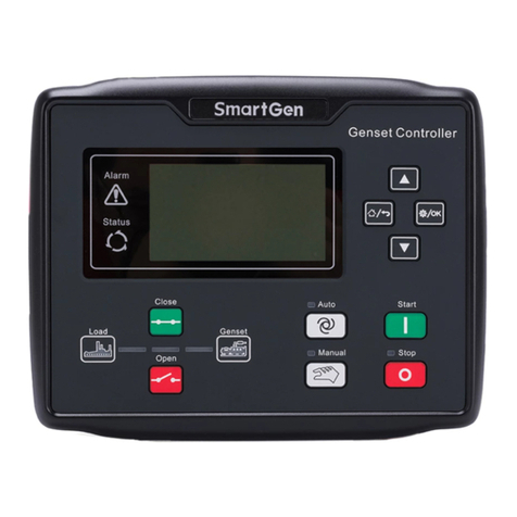
4.1 KEY FUNCTION
Table 3 - Key Function Descriptions
Icon
Function
Description
Stop/ Reset
Stop the running genset both in Auto/Manual mode;
Remove the alarm in stop mode;
Press for 3 seconds or over and panel indicators can be tested
(lamp test);
Press again in stop process and genset shall stop immediately.
Start
Start genset in manual mode.
Manual
Set the module to manual mode.
Auto
Set the module to auto mode.
C/O
Control breaker close and open in manual mode.
Set/Confirm
Enter menu list page;
Move cursor in parameter setting and confirm the set information.
Up/Increase
Scrolls the screen up;
Shift cursor up or increase the set value in parameter setting.
Down/Decrease
Scrolls the screen down;
Shift cursor down or decrease the set value in parameter setting.
Home/Return
Return to home page in main interface;
Return to last interface in parameter setting;
Press for 3 seconds or over, trip alarm can be reset.
NOTE: press any key to mute alarms in main screen.
HGM7220N/HGM7220S GENSET CONTROLLER USER MANUAL
HGM7220N/HGM7220S Genset Controller 2019-02-28 Version 1.0 Page 10 of 60
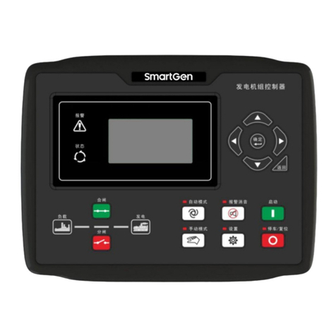
4.2 CONTROLLER PANEL
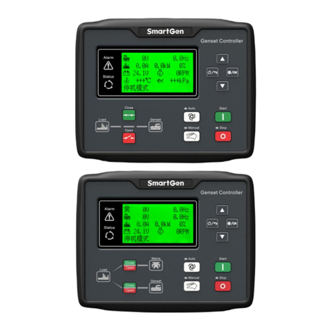
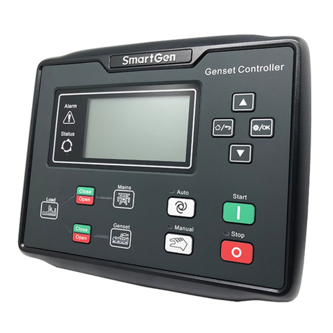
Figure 1 - HGM7220N/7220S Front Panel Indication
NOTE: Illustration for part indicators.
Table 4 - Alarm Indicator Description
Alarm Type
Alarm Indicators
Warning alarm
slowly flashing (once per second)
Trip alarm
slowly flashing (once per second)
Shutdown alarm
fast flashing (5 times per second)
Trip and stop alarm
fast flashing (5 times per second)
NOTES:
a) Status Indicators: illuminate always after crank disconnection and before ETS; extinguished during other periods.
b) Gen Normal Indicator: illuminates always when generator is normal; flashes when generator is abnormal;
extinguished when generator is standby.
c) Mains Normal Indicator: illuminates always when mains is normal; flashes when mains is in fault; extinguished
when gen is standby.
d) When mains is disabled, mains normal indicator is extinguished, and meanwhile mains C/O key does not work.
HGM7220N/HGM7220S GENSET CONTROLLER USER MANUAL
HGM7220N/HGM7220S Genset Controller 2019-02-28 Version 1.0 Page 11 of 60
4.3 AUTO START/STOP OPERATION
4.3.1. ILLUSTRATION
Press and the indicator beside is illuminated, meaning genset is inAuto Start mode.
4.3.2. AUTO START SEQUENCE
a) HGM7220N/HGM7220S Start Conditions:
Mains Enable: When mains is abnormal (over and under voltage, over and under frequency, loss of
phase and inverse phase), genset enters “mains abnormal delay” and LCD displays countdown time.
When mains abnormal delay is over, it enters “start delay”. Or when remote start (load on) input is active,
it enters “start delay”.
Mains Disable: When remote start (load on) input is active, genset enters “start delay”.
b) “start delay”countdown is shown on LCD.
c) When start delay is over, preheating relay outputs (if configured), “Pre-heat
Delay XX s” is shown on LCD.
d) When preheating delay is over, fuel relay outputs for 1s. Then start relay outputs; if engine cranking
fails during “cranking time”, the fuel relay and start relay are deactivated and enter “crank rest time”
waiting for next crank.
e) If engine crank fails within setting times, controller will initiate “failed to start” shutdown signal and
“failed to start” message appears on LCD display at the same time.
f) In case of successful cranking, “safety on time” starts. During this period, low oil pressure, high water
temperature, under speed, and charge failure alarms are disabled. As soon as “safety on delay”is
over, “start idle delay” is initiated (if configured).
g) During “start idle delay” period, under speed, under frequency, under voltage alarms are inhibited.
When this delay is over, “warming up delay” starts (if configured).
h) In case mains is abnormal and HGM7220N remote start (on-load) input is active, when “warming up
delay” is over, if generator status is normal, the indicator will be illuminated; if voltage and frequency
has reached to on-load requirements, the closing relay will be energized, generator will accept load,
generator power indicator will be lit on, and generator will enter Normal Running status; if voltage and
frequency are abnormal, the controller will initiate shutdown alarm (shutdown alarm will be displayed
on LCD alarm page).
i) In case HGM7220S remote start (on-load) input is active, when “warming up delay”is over, if
generator status is normal then the generator status indicator shall be illuminated. Until genset and
mains satisfy the synchronization conditions, the controller shall issue close signal and when the
controller detects the close feedback signal, it shall issue immediately the open signal, and genset is
on-load.
NOTE: when remote start (off-load) signal input is active, the auto start sequence is the same as above except
item h), generator closing relay will not output, and genset is off-load.
4.3.3. AUTO STOP SEQUENCE
a) In case HGM7220N/7220S genset is at normal running, if mains recovers normal, genset shall enter
mains voltage “normal delay”. As soon as mains normal status is confirmed, mains status indicator
shall be illuminated and “stop delay”starts; Or if remote start input is not active, “stop delay”starts.
b) As soon as “stop delay”is over,
HGM7220N/HGM7220S GENSET CONTROLLER USER MANUAL
HGM7220N/HGM7220S Genset Controller 2019-02-28 Version 1.0 Page 12 of 60
①HGM7220N: starts “cooling delay”, meanwhile generating close relay is disconnected.After “transfer
reset delay”, mains close relay outputs, mains is on-load, gens power supply indicator is light off,m
and mains supply indicator is light on.
②HGM7220S: and mains meet the synchronization conditions, the controller shall issue mains close
signal.When the controller detects mains close feedback signal,it shall give outimmediately the gens
open signal, gens supply indicator is extinguished, mains is on-load, mains supply indicator is
illuminated, and genset starts “cooling delay”.
c) When genset enters “stop idle delay”(if configured), idle relay is energized and outputs.
d) When genset enters “ETS hold delay”, ETS relay is energized. Fuel relay is deactivated and detects
whether it stops or not automatically.
e) Then it enters “wait stop time”, and controller shall detects whether genset stops or not is
automatically.
f) After genset is stopped completely, it enters “after stop delay”, otherwise it enters “failed to stop”and
the controller issue “failed to stop”warning (after stop failure warning, if gen-set stops after the alarm,
it will enter “after stop delay” and “failed to stop” alarm will be eliminated automatically).
g) When “after stop delay”is over, genset shall enter standby status.
4.4 MANUAL START/STOP OPERATION
a) HGM7220N/7220S: Press button and controller enters “Manual Mode”, Manual Mode indicator
is illuminated. In this mode, Press button and genset is started. Start success is detected
automatically and genset goes up to high speed running automatically. In case high water
temperature, low oil pressure, over speed and abnormal voltage occur during diesel genset running,
controller can effectively protect genset to stop (for detailed procedures please refer to 4.3.2 Auto
Start Sequence c~i.). In manual mode, load breaker won’t transfer automatically. It needs to press
C/O key to open/close.
b) Manual Stop: press key and the running genset shall be stopped. (for detailed procedures
please refer to 4.3.3Auto Stop Sequence b-g.)
4.5 EMERGENCY START
Simultaneously press and in manual mode and the generator shall be forced to crank.
Successful start will not be judged according to crank disconnect conditions, but controlled by operator.
When operator observes that the genset has started, he/she should release the button and start output
will be deactivated. “Safety on delay”will be initiated.
5 BREAKER CONTROL PROCESS OF GENSET CONTROLLER
5.1 HGM7220N BREAKER CONTROL PROCESS
5.1.1. MANUAL SWITCHING PROCESS
Breaker is switched by manual control if controller in manual mode.
HGM7220N/HGM7220S GENSET CONTROLLER USER MANUAL
HGM7220N/HGM7220S Genset Controller 2019-02-28 Version 1.0 Page 13 of 60
Operator controls load transfer ofATS via pressing button.
Mains Enable: When breaker open detection is disabled, (1) press generator button, open
breaker will output if generator is on-load; generator will be closed if load is disconnected; mains will
be opened if mains is on-load, and generator is closed after open delay is over; (2) press mains
button, if mains is on-load, open breaker output; if load is disconnected, mains will be closed; if
generator is on-load, generator will be opened, and mains will be closed after open delay is over.
If breaker open detection is enabled, mains on-load is changed to gens on-load. It is needed to
press mains and press generator after open delay, then generator is closed (directly
press gens close button, and none action occurs.). Gens on-load is changed to mains on-load, which
is the same as above.
Mains Disable: Press generator button, and if generator is not on-load, then generator
close outputs. Press generator and if generator is on-load, then generator open outputs.
5.1.2. AUTO SWITCHING PROCESS
Breaker is switched by automatic control if controller is in auto mode or stop mode.
a) In case input port is configured as close status auxiliary input,
Mains Enable:
When breaker open detection is enabled, mains on-load changes to generator on-load.After open
delay and transfer rest delay, in the process of open output, transfer failure is detected. When the
detection time is due, if open fails, then generator close does not occur, otherwise generator close
occurs. In the process of generator close, transfer failure is detected. When the detection time is due, if
close fails, then generator close is waited for. If transfer failure warning is enabled, then open/close
failures shall issue warning signals. For generator on-load transfers to mains on-load, it is the same
process as above.
When breaker open detection is disabled, mains on-load changes to generator on-load. After
open delay and transfer rest delay, generator close occurs. In the process of generator close, transfer
failure is detected. When the detection time is due, if close fails, then generator close is waited for. If
transfer failure warning is enabled, then warning signal is issued. For generator on-load transfers to
mains on-load, it is the same process as above.
Mains Disable:
When breaker open detection is enabled, mains on-load changes to generator on-load.After open
delay in the process of open output, transfer failure is detected.When the detection time is due, if open
fails, then open is waited for, otherwise open is completed. For generator off-load changing to
generator on-load, after close delay, in the process of close output, transfer failure is detected. When
the detection time is due, if close fails, then close is waited for, otherwise close is completed.
If transfer failure warning is enabled, then open/close failures shall issue warning signals.
When breaker open detection is disabled, generator on-load changes to generator off-load. After
open delay, open is completed. For generator off-load changing to generator on-load, after close delay,
in the process of close output, transfer failure is detected. When the detection time is due, if close fails,
then close is waited for, otherwise close is completed. If transfer failure warning is enabled, then close
HGM7220N/HGM7220S GENSET CONTROLLER USER MANUAL
HGM7220N/HGM7220S Genset Controller 2019-02-28 Version 1.0 Page 14 of 60
failure shall issue warning signal.
b) In case input port is not configured as close status auxiliary input,
Mains Enable:
For mains on-load changing to generator on-load, after open delay and transfer rest delay,
generator close occurs. For generator on-load changing to mains on-load, it is the same as above.
Mains Disable:
For generator off-load changing to generator on-load, generator close outputs. For generator
on-load changing to generator off-load, generator open outputs.
NOTE: In case of applying ATS without neutral breaking, open detection shall be disabled.
NOTE: In case of applying ATS with neutral breaking, open detection can be enabled and disabled. If it is enabled,
please configure open output.
NOTE: In case of applying AC contactor, open detection is recommended to be enabled.
5.2 HGM7220S BREAKER CONTROL PROCESS
5.2.1. MANUAL SWITCHING PROCESS
Breaker is switched by manual control if controller in manual mode.
Operator controls ATS load transfer via C/O button.
Mains Enable:
Press generator button,
1. In case of generator on-load, then generator open outputs;
2. In case of generator&mains off-load, then generator close occurs;
3. In case of mains on-load, when generator synchronization close is over, mains open occurs and
generator is on-load.
NOTE: In the process of waiting for synchronization or if synchronization fails, press generator C/O button to cancel
synchronization, and generator breaker is open. Then press mains C/O button to force mains on-load.
Mains Disable:
Press generator C/O button, and if generator is off-load, then generator close outputs; if generator
is on-load, then generator open outputs.
5.2.2. AUTO SWITCHING PROCESS
Breaker is switched by automatic control if controller in auto mode.
Mains Enable:
1. For mains on-load changing to generator on-load,
Controller shall output generator close when genset and mains meet synchronization conditions.
When it detects generator close feedback signal, mains open outputs and generator is on-load. If
generator close is outputted, generator close feedback signal is not detected during the C/O
synchronization period, generator open is outputted and mains is on-load. Mains open status is
detected at the time of mains open output. When the C/O synchronization time is due, if mains open
fails, generator open outputs. If synchronization signal is not detected during the set synchronization
failure time, then synchronization failure alarm is issued. If synchronization failure alarm is warning
and transfer is forced to be enabled after synchronization failure ten mains open outputs. After open
delay, mains open status is detected at the time of mains open output. When detection time is due, if
mains open fails, then generator shall not close, otherwise, after transfer delay generator close outputs.
Generator close status is detected at the time of generator close output. When the detection time is
HGM7220N/HGM7220S GENSET CONTROLLER USER MANUAL
HGM7220N/HGM7220S Genset Controller 2019-02-28 Version 1.0 Page 20 of 60
6.4 TRIP ALARM
When controller detects trip alarms, it will immediately disconnect the generator close signals but
genset does not stop.
Table 8 - Trip Alarms
No.
Type
Description
1
Over Current
When controller detects the genset current value is higher than the set
value and action is selected “Trip”, it will send trip signals.
2
Reverse Power
When controller detects that the genset reverse power value (power is
negative) exceeds the pre-set value, and action is selected “Trip”, it will
send trip signals.
3
Over Power
When controller detects that the genset power value (power is positive)
exceeds the pre-set value, and action is selected “Trip”, it will send trip
signals.
4
Input Trip
When input port is configured as “Trip”, and if it is active, controller will
send trip signals.
5
Mains Breaker
Fail
HGM7220S controller: when controller detects mains C/O fails, it shall
issue the alarm signal.
6
Gen Breaker Fail
HGM7220S controller: when controller detects generator C/O fails, it shall
issue the alarm signal.
7
Fail to Sync
HGM7220S controller: When controller is in auto mode, if synchronization
signal is not detected during the synchronization time for mains/generator
synchronization close, it shall issue a warning signal.
HGM7220N/HGM7220S GENSET CONTROLLER USER MANUAL
HGM7220N/HGM7220S Genset Controller 2019-02-28 Version 1.0 Page 21 of 60
7 WIRINGS CONNECTION
HGM7220N/7220S controller back panel is as below.
Figure 2 - Back Panel
HGM7220N/HGM7220S GENSET CONTROLLER USER MANUAL
HGM7220N/HGM7220S Genset Controller 2019-02-28 Version 1.0 Page 22 of 60
Table 9 - Terminal Wiring Connection
No.
Function
Cable Size
Remarks
1
B-
2.5mm2
Connected with negative of starter battery.
2
B+
2.5mm2
Connected with positive of starter battery. If wire length
is over 30m, it’s better to double wires in parallel. Max.
20Afuse is recommended.
3
Emergency Stop
2.5mm2
Connect with B+ via emergency stop button.
4
Fuel (16A)
1.5mm2
B+ is supplied by Terminal 3, rated 16A.
5
Crank (16A)
1.5mm2
B+ is supplied by Terminal 3, rated 16A.
Connect with starting coil of starter.
6
Aux. Output 1(8A)
1.5mm2
B+ is supplied by Terminal 2, rated 8A.
7
Aux. Output 2(8A250VAC)
1.5 mm2
NC output, rated 8A.
For items please see
Table 11.
8
Relay common port.
9
NO output, rated 8A.
10
Aux. Output 3(16A 250VAC)
2.5 mm2
Relay NO volt free contact,
rated 16A, volt free contact
output.
11
12
Aux. Output 4(16A 250VAC)
2.5 mm2
13
14
Charger(D+)
1.0mm2
Connected with charger starter’s D+ (WL) terminal.
Please hang it up if there is not this terminal.
15
Aux. Output 5(8A)
1.5 mm2
B+ is supplied by Terminal
2, rated 8A
For items please see
Table 11.
16
Aux. Output 6(8A)
1.5 mm2
17
Speed Sensor Input
Connect with speed sensor, and shielded wire is recommended.
18
Speed sensor input, battery
negative electrode has been
connected inside controller.
19
Engine Temp.
Connect with temperature sensor
For items please see
Table 13.
20
Oil Pressure
Connect with pressure sensor
21
Fuel Level
Connect with fuel level sensor
22
Aux. Input 1
1.0mm2
Ground connected is active (B-)
For items please see
Table 12.
23
Aux. Input 2
1.0mm2
Ground connected is active (B-)
24
Aux. Input 3
1.0mm2
Ground connected is active (B-)
25
Aux. Input 4
1.0mm2
Ground connected is active (B-)
26
Aux. Input 5
1.0mm2
Ground connected is active (B-)
27
Sensor Common Port
Sensor common port, battery negative electrode has been
connected inside controller.
28
Aux. Input 6
1.0mm2
Ground connected is active (B-)
For items please see
Table 12.
29
Aux. Input 7
1.0mm2
Ground connected is active (B-)
HGM7220N/HGM7220S GENSET CONTROLLER USER MANUAL
HGM7220N/HGM7220S Genset Controller 2019-02-28 Version 1.0 Page 23 of 60
No.
Function
Cable Size
Remarks
30
Configurable Sensor 1
Connected with temp/pressure/fuel level
sensor.
For items please see
Table 13.
31
Configurable Sensor 2
32
CTA-phase Monitoring Input
1.5mm2
Outside connected to secondary coil of CT (5A rated).
33
CT B-phase Monitoring Input
1.5mm2
Outside connected to secondary coil of CT (5A rated).
34
CTC-phase Monitoring Input
1.5mm2
Outside connected to secondary coil of CT (5A rated).
35
CT Common Port
1.5mm2
Details to see the following installation description.
36
Gen U-phase Voltage
Monitoring Input
1.0mm2
Connected to U-phase output of genset (2Afuse
recommended).
37
Gen V-phase Voltage
Monitoring Input
1.0mm2
Connected to V-phase output of genset (2Afuse
recommended).
38
Gen W-phase Voltage
Monitoring Input
1.0mm2
Connected to W-phase output of genset (2A fuse
recommended).
39
Gen N2-line Input
1.0mm2
Connected to N-line output of genset.
40
Mains R-phase Voltage
Monitoring Input
1.0mm2
Connected to R-phase of mains (2Afuse
recommended).
41
Mains S-phase voltage
monitoring input
1.0mm2
Connected to S-phase of mains (2Afuse
recommended).
42
Mains T-phase voltage
monitoring input
1.0mm2
Connected to T-phase of mains (2Afuse recommended).
43
Mains line N1 Input
1.0mm2
Connected to N-line of mains.
44
Terminal Resistor (120Ω)
0.5mm2
If 120Ω resistor is needed, short connect 44 and 46.
45
RS485-
0.5mm2
120Ωshielding wire is recommended with single end
ground connected.
46
RS485+
0.5mm2
47
VOUT(+5V)
0.5mm2
Output DC +5V.
48
NC
49
ECU CAN L
0.5mm2
120Ωshielding wire is recommended with single end
ground connected. Between CAN L and CAN H there is
already 120Ωresistor inside the controller.
50
ECU CAN H
0.5mm2
NOTE: USB ports in controller rear panel are programmable parameter ports, and users can directly configure the
controller on PC.
NOTE: Modem expansion module can be connected from the rear panel.
HGM7220N/HGM7220S GENSET CONTROLLER USER MANUAL
HGM7220N/HGM7220S Genset Controller 2019-02-28 Version 1.0 Page 24 of 60
8 SCOPES AND DEFINITIONS OF PROGRAMMABLE PARAMETERS
8.1 CONTENTS AND SCOPES OF PARAMETERS
Table 10 - Parameter Settings and Scope
No.
Items
Range
Default
Description
Mains Setting
1
Mains Enable
(0-1)
1
0: Disable; 1: Enable
2
AC System
(0-3)
0
0: 3P4W;
1: 3P3W
2: 2P3W
3: 1P2W
3
Rated Voltage
(30-30000)V
230
Provide standard for judging mains
over/under voltage or not; if voltage
transformer is applied, this value is the
primary voltage of transformer.
4
Rated Frequency
(10.0-75.0)Hz
50.0
Provide standard for judging mains
over/under frequency or not.
5
Normal Time
(0-3600)s
10
The time from mains abnormal to normal.
6
Abnormal Time
(0-3600)s
5
The time from mains normal to abnormal.
7
Voltage
Transformer (PT)
(0-1)
0
0: Disabled; 1: Enabled
8
Over Voltage
(0-200)%
120
The setting value is mains rated voltage
percentage; return value and delay value
also can be set.
9
Under Voltage
(0-200)%
80
10
Over Frequency
(0-200)%
Disabled
The setting value is mains rated frequency
percentage; return value and delay value
also can be set.
11
Under Frequency
(0-200)%
Disabled
12
Loss of Phase
Check
(0-1)
1
0: Disabled; 1: Enabled
13
Reverse Phase
(0-1)
1
Timer Setting
1
Start Delay
(0-3600)s
1
Time between mains abnormal or remote
start signal is active and genset start.
2
Return Delay
(0-3600)s
1
Time between mains normal or remote start
signal is deactivated and genset stop.
3
Preheat Delay
(0-3600)s
0
Power-on time of heater plug before starter
is powered up.
4
Cranking Time
(3-60)s
8
Each starter power-on time
5
Crank Rest Time
(3-60)s
10
The waiting time before second power up
when engine start fails.
6
Safety On Time
(0-3600)s
10
Alarms for low oil pressure, high temp,
under speed, under frequency/voltage,
charge alt failure are deactivated.
7
Start Idle Time
(0-3600)s
0
Running time for idling speed when genset
starts up.
8
Warming Up Time
(0-3600)s
10
Warming up time for genset after entering
high speed running before breaker close.
HGM7220N/HGM7220S GENSET CONTROLLER USER MANUAL
HGM7220N/HGM7220S Genset Controller 2019-02-28 Version 1.0 Page 33 of 60
No.
Items
Range
Default
Description
SGE02-4G Setting
1
SGE02-4G Enable
(0-1)
1
0: Disabled; 1: Enabled
2
SMS Enable
(0-1)
0
0: Disabled; 1: Enabled
3
Mobile Number
Max. 20 bits
All numbers are needed to add district or country
number, e.g. China 13666666666.
4
GPRS Enable
(0-1)
1
0: Disabled; 1: Enabled
5
GPS Enable
(0-1)
1
0: Disabled; 1: Enabled
6
Longitude
(-180-180)°
113.33
When GPS is disabled, monitor module
GPS position and altitude information can be
inputted.
7
Latitude
(-90-90)°
34.48
8
Altitude
(-9999.9-9999.9)m
100
Cloud Server Setting
1
Site Name
20 characters/40 letters/40 numbers
2
URL Server
www.monitoryun.com
3
Server Port
(0-65535)
91
4
Module Password
123456
16 characters
8.2 DEFINITION CONTENT OF PROGRAMMABLE OUTPUT PORTS 1~6
Table 11 - Programmable Output Ports 1~6
No.
Type
Description
0
Not Used
1
Custom Period 1
For details about function description please see the following
content.
2
Custom Period 2
3
Custom Period 3
4
Custom Period 4
5
Custom Period 5
6
Custom Period 6
7
Custom Combined 1
8
Custom Combined 2
9
Custom Combined 3
10
Custom Combined 4
11
Custom Combined 5
12
Custom Combined 6
13
Reserved
14
Reserved
15
Reserved
16
Reserved
17
Air Flap Control
It is activated when over speed shutdown and emergency
shutdown alarms occur, which can turn off the engine intake.
18
Audible Alarm
It is activated when warning, shutdown and electrical trip
alarms appear. Announciator can be connected externally; if
aux. input port is configured as “Mute Alarms”and if it is
HGM7220N/HGM7220S GENSET CONTROLLER USER MANUAL
HGM7220N/HGM7220S Genset Controller 2019-02-28 Version 1.0 Page 45 of 60
Table 15 - Common Unit Conversion Table
Items
N/m2 (pa)
kgf/cm2
bar
(p/in2.psi)
1Pa
1
1.02x10⁻⁵
1x10⁻⁵
1.45x10⁻⁴
1kgf/cm2
9.8x10⁴
1
0.98
14.2
1bar
1x10⁵
1.02
1
14.5
1psi
6.89x10³
7.03x10⁻²
6.89x10⁻²
1
12 COMMISSIONING
Please make sure the following checks are made before commissioning,
—Ensure all the wiring connections are correct and wire diameter is suitable.
—Ensure that the controller DC power has fuse, and controller’s positive and negative and start battery
are correctly connected.
—Emergency stop input is connected to the positive pole of starter battery via emergency stop button’s
normally closed point and fuse.
—Take proper actions to prevent engine from cranking successfully (e. g. Remove the connection wire
of fuel valve). If checking is OK, make the start battery power on; choose manual mode and controller
will executive routine.
—Set controller under manual mode, press “start” button, and genset will start. After the cranking times
set before, controller will send signal of Start Failure; then press “stop” to reset controller.
—Recover the action to prevent engine from cranking successfully (e. g. Connect wire of fuel valve),
press start button again, and genset will start. If everything goes well, genset will be normally running
after idle running (if idle run is set). During this time, please watch engine’s running situation and AC
generator’s voltage and frequency. If there is something abnormal, stop genset and check all wiring
connections according to this manual.
—Select the AUTO mode from controller’s panel, and connect mains signal. After the mains normal
delay, controller will transfer ATS (if set) into mains load. After cooling time, controller will stop genset
and make it into “at rest” mode until there is mains abnormal situation.
—When mains is abnormal again, genset will be started automatically and enter into normal running,
then controller send signal to make generator switch on, and control the ATS transfer into generator
load. If it is not like this, please check ATS’ wiring connection according to this manual.
—If there is any other question, please contact SmartGen’s service.
HGM7220N/HGM7220S GENSET CONTROLLER USER MANUAL
HGM7220N/HGM7220S Genset Controller 2019-02-28 Version 1.0 Page 46 of 60
13 TYPICAL APPLICATION
Figure 4 - HGM7220S Typical Application
Figure 5 - HGM7220N Typical Application
HGM7220N/HGM7220S GENSET CONTROLLER USER MANUAL
HGM7220N/HGM7220S Genset Controller 2019-02-28 Version 1.0 Page 47 of 60
Figure 6 - Single Phase 2-Wire Connection Diagram
Figure 7 –2-Phase 3-Wire Connection Diagram
NOTE: Expand relay with high capacity in start and fuel output is recommend.
14 INSTALLATION
14.1 SGE02 EXPANSION MODULE
14.1.1 4G ANTENNA PORT
Connect 4G antenna and 4G port of SGE02.
Antenna port: 50Ω/SMA USB.
14.1.2 GPS ANTENNA PORT
Make GPS function enable, and connect GPS antenna and GPS port of SGE02.
NOTE: GPS antenna needs to be placed at open outdoor, otherwise location information shall be incorrect, or
cannot be obtained.
Antenna port: 50Ω/SMA USB. Active antenna.
HGM7220N/HGM7220S GENSET CONTROLLER USER MANUAL
HGM7220N/HGM7220S Genset Controller 2019-02-28 Version 1.0 Page 48 of 60
Figure 8 - HGM7220N/7220S Antenna Connection
14.1.3 SIM CARD INSTALLATION
Insert 4G, 3G or 2G SIM card, and connect it with servicer via wireless network.
NOTE: This module supports 4G wireless network fitting all networks. Standard SIM card (size: 25mmx15mm) is
applied. It displays on the controller, and this means SIM is not inserted or SIM contact is not good.
Please refer to the following installation steps.
Figure 9 –SIM Installation Steps
14.2 FIXING CLIPS
—Controller is panel built-in design; it is fixed by clips when installed.
—Withdraw the fixing clip screw (turn anticlockwise) until it reaches proper position.
—Pull the fixing clip backwards (towards the back of the module) and ensure two clips are inside their
allotted slots.
—Turn the fixing clip screws clockwise until they are fixed on the panel.
—Care should be taken not to over tighten the screws of fixing clips.
HGM7220N/HGM7220S GENSET CONTROLLER USER MANUAL
HGM7220N/HGM7220S Genset Controller 2019-02-28 Version 1.0 Page 49 of 60
14.3 OVERALL DIMENSION
Figure 10 - Overall Dimensions
HGM7220N7220S series controller can suit for wide range of battery voltage DC (8~35) V. Negative
of battery must be connected with the engine shell. Diameter of wire that connects power supply with
battery must be over 2.5mm2. If floating charger is configured, please firstly connect output wires of
charger to battery’s positive and negative directly, then, connect wires from battery’s positive and negative
to controller’s positive and negative input ports in order to prevent charger disturbing the controller’s
normal working.
—SPEED SENSOR INPUT: Speed sensor is the magnetic equipment installed in starter and for
detecting flywheel teeth. Its connection wires with the controller should apply 2-core shielding line. The
shielding layer should connect to No. 18 terminal in controller while another side is hanging in air. The
else two signal wires are connected to No.17 and No.18 terminals in controller. The output voltage of
speed sensor should be within (1~24) VAC (effective value) during the full speed. 12VAC is
recommended (in rated speed). When the speed sensor is installed, let the sensor spun to contacting
flywheel first, then, make it back 1/3 lap, and lock the nuts of sensor at last.
—OUTPUT AND EXPAND RELAYS: All outputs of controller are relay contact output type. If expansion
relays are needed, please add freewheel diode to both ends of expansion relay’s coils (when coils of relay
has DC current) or, increase resistance-capacitance return circuit (when coils of relay has AC current), in
order to prevent disturbance to controller or other equipments.
—AC INPUT: Current input of HGM7220N/7220S series controller must be connected to outside current
transformer. And the current transformer’s secondary side current must be 5A. At the same time, the
phases of current transformer and input voltage must be correct. Otherwise, the current collected and
active power maybe not be correct.
—WITHSTAND VOLTAGE TEST: When controller had been installed on display window, if the high
voltage test is needed, please disconnect controller’s all terminal connections, in order to prevent high
voltage getting into controller and damaging it.
NOTES:
a) ICOM portmust be connected to negative pole of battery.
b) When there is load current, open circuit is prohibited on transformer’s secondary side.

Other manuals for HGM7220N Series

1

This manual suits for next models

1

Other Smartgen Controllers manuals

Smartgen HGM8151 User manual

Smartgen

Smartgen HGM8151 User manual

Smartgen ALC700 SERIES User manual

Smartgen

Smartgen ALC700 SERIES User manual

Smartgen HGM1790N User manual

Smartgen

Smartgen HGM1790N User manual

Smartgen HGM7100N Series User manual

Smartgen

Smartgen HGM7100N Series User manual

Smartgen HGM6100U2C Series User manual

Smartgen

Smartgen HGM6100U2C Series User manual

Smartgen HGM9510N User manual

Smartgen

Smartgen HGM9510N User manual

Smartgen HAT880 Series User manual

Smartgen

Smartgen HAT880 Series User manual

Smartgen HGM1790N User manual

Smartgen

Smartgen HGM1790N User manual

Smartgen HAT530 User manual

Smartgen

Smartgen HAT530 User manual

Smartgen HGM9420N User manual

Smartgen

Smartgen HGM9420N User manual

Smartgen HGM9560 User manual

Smartgen

Smartgen HGM9560 User manual

Smartgen APC715N User manual

Smartgen

Smartgen APC715N User manual

Smartgen HAT530N User manual

Smartgen

Smartgen HAT530N User manual

Smartgen HAT160 User manual

Smartgen

Smartgen HAT160 User manual

Smartgen FPC1700 User manual

Smartgen

Smartgen FPC1700 User manual

Smartgen GENSET HGM8100N Series User manual

Smartgen

Smartgen GENSET HGM8100N Series User manual

Smartgen HGM8100A User manual

Smartgen

Smartgen HGM8100A User manual

Smartgen HGM7110DC User manual

Smartgen

Smartgen HGM7110DC User manual

Smartgen HMAT880 User manual

Smartgen

Smartgen HMAT880 User manual

Smartgen HGM6110U User manual

Smartgen

Smartgen HGM6110U User manual

Smartgen MGC120 User manual

Smartgen

Smartgen MGC120 User manual

Smartgen HGM6000K Series User manual

Smartgen

Smartgen HGM6000K Series User manual

Smartgen HAT600R Series User manual

Smartgen

Smartgen HAT600R Series User manual

Smartgen HGM410E User manual

Smartgen

Smartgen HGM410E User manual

Popular Controllers manuals by other brands

Mitsubishi Electric MELSEC iQ-R RD78G4 user manual

Mitsubishi Electric

Mitsubishi Electric MELSEC iQ-R RD78G4 user manual

AUMA SGExC 05.1 Operation instructions

AUMA

AUMA SGExC 05.1 Operation instructions

Baier PROMETHEUS Series instruction manual

Baier

Baier PROMETHEUS Series instruction manual

MTT MS3714 user manual

MTT

MTT MS3714 user manual

Omron V680-CA5D01-V2 instruction sheet

Omron

Omron V680-CA5D01-V2 instruction sheet

YASKAWA MP2200 manual

YASKAWA

YASKAWA MP2200 manual

ABB ISL-A 24 instruction manual

ABB

ABB ISL-A 24 instruction manual

Consort SLPBWIFI Installation & Control Guide

Consort

Consort SLPBWIFI Installation & Control Guide

elero InDrive M30/1.6 RH Operating and assembly instructions

elero

elero InDrive M30/1.6 RH Operating and assembly instructions

OPTOGAMA LPA-A v2 Series manual

OPTOGAMA

OPTOGAMA LPA-A v2 Series manual

Digital Equipment DEC WANcontroller 618 Problem Solving

Digital Equipment

Digital Equipment DEC WANcontroller 618 Problem Solving

Swagelok RS20 user manual

Swagelok

Swagelok RS20 user manual

Epson RC420 manual

Epson

Epson RC420 manual

Sol SolCon-016 Operation manual

Sol

Sol SolCon-016 Operation manual

GE PACSystems* RX3i user manual

GE

GE PACSystems* RX3i user manual

HTW HTW-KJR86A1E Installation and operation manual

HTW

HTW HTW-KJR86A1E Installation and operation manual

NTN K-EGA57 instruction manual

NTN

NTN K-EGA57 instruction manual

Toho Electronics TTM-300 Series instruction manual

Toho Electronics

Toho Electronics TTM-300 Series instruction manual

manuals.online logo
manuals.online logoBrands
  • About & Mission
  • Contact us
  • Privacy Policy
  • Terms and Conditions

Copyright 2025 Manuals.Online. All Rights Reserved.