Shinco SDP1850 User manual

SERVICE MANUAL
CAUTION : Before servicing this chassis, read the "PRODUCT SAFETY SERVICE FOR VIDEO PRODUCTS" section
on page 2 of this manual.
CONTENTS
SERVICE PRECAUTIONS......................................................2,3
BLOCK DIAGRAMS...................................................................4
TROUBLE SHOOTING...........................................................5,8
BOARD DIAGRAM...............................................................9,10
DVD and CD
PLAYER
MODEL
SDP1850
REPLACEMENT PARTS LIST................................................11
Whenthepowersupplyisbeingturnedon,youmaynotremovethislasercautionslabel.Ifitremoves,radiationoflaser
maybereceived.
LASERBEAMCAUTIONLABEL
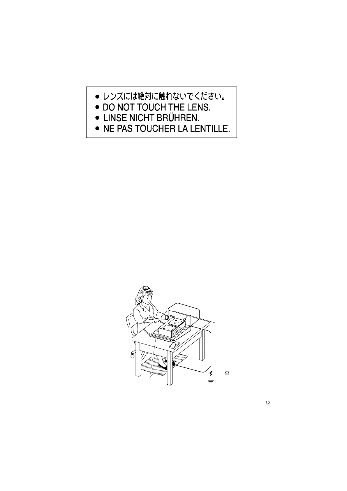
PREPARATIONOFSERVICING
PickupHeadconsistsofalaserdiodethatisverysusceptibletoexternalstaticelectrocity.
Althoughitoperatesproperlyafterreplacement,ifitwassubjecttoelectrostaticdischargeduringreplacement,
itslifemightbeshortened.Whenreplacing,useaconductivemat,solderingironwithgroundwire,etc.to
protectthelaserdiodefromdamagebystaticelectricity.
Andalso,theLSIandICaresameasabove.
Solderingiron
withgroundwire
orceramictype
Groundconductive
wriststrapforbody.
Conductivemat
Thegroundresistance
betweenthegroundline
andthegroundislessthan10
1M
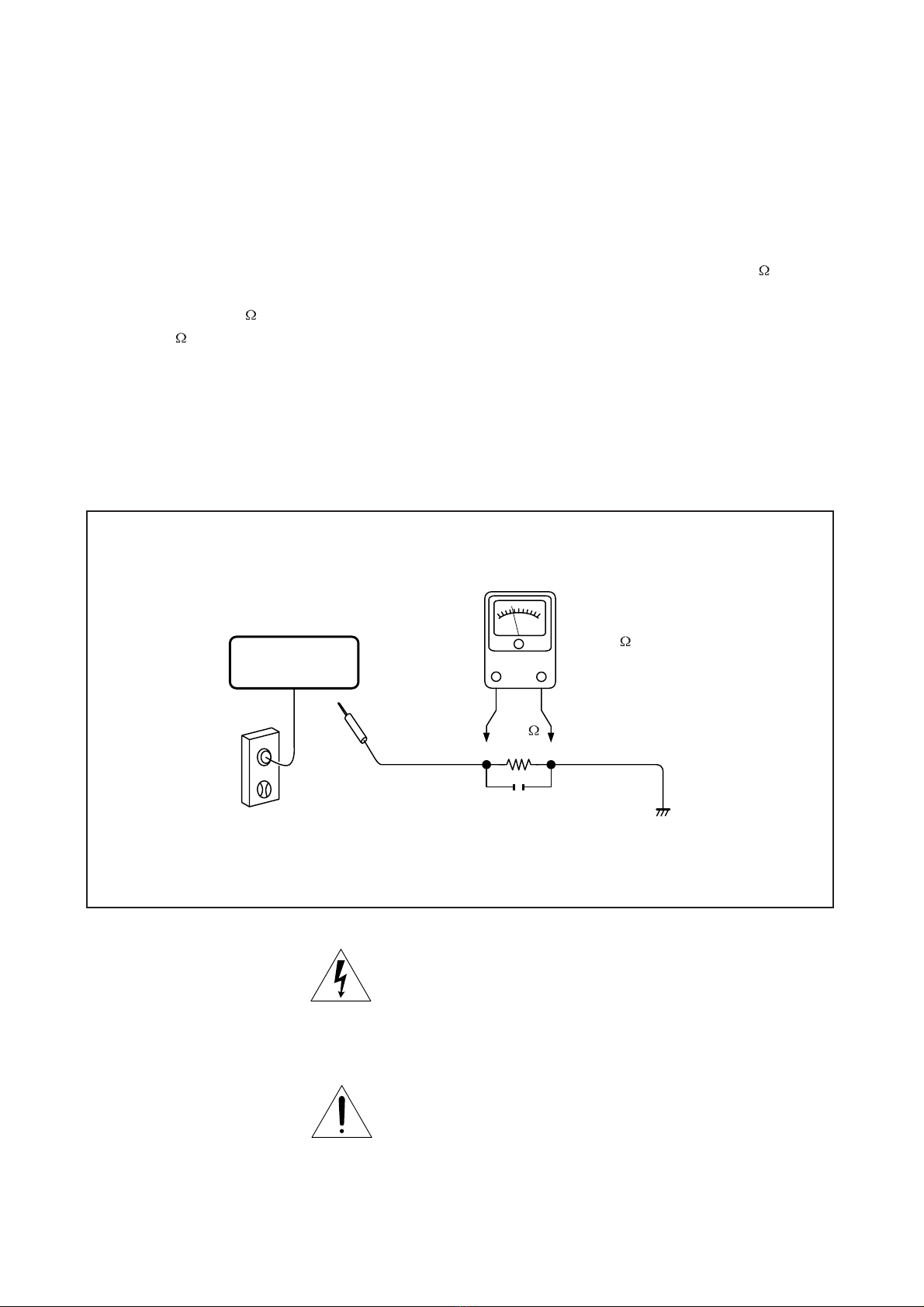
SAFTY NOTICE
Plug the AC line cord directly into a 120V AC outlet (do
not use an isolation transformer for this check). Use an
AC voltmeter, having 5000 per volt or more sensitivity.
Connect a 1500 10W resistor,paralleled by a 0.15uF
150V AC capacitor between a knomn good earth ground
(water pipe, conduit, etc.) and all exposed metal parts of
cabinet (antennas, handle bracket, metal cabinet
screwheads, metal overlays, control shafts, etc.).
SAFTY PRECAUTIONS
LEAKAGE CURRENT CHECK
Measure the AC voltage across the 1500 resistor.
The test must be conducted with the AC switch on and
then repeated with the AC switch off. The AC voltage
indicated by the meter may not exceed 0.3V.A reading
exceeding 0.3V indicates that a dangerous potential
exists, the fault must be located and corrected.
Repeat the above test with the DVD VIDEO PLAYER
power plug reversed.
NEVER RETURN A DVD VIDEO PLAYER TO THE
CUSTOMER WITHOUT TAKING NECESSARY
CORRECTIVE ACTION.
READING SHOULD NOT EXCEED 0.3V
DVD VIDEO PLAYER
AC OUTLET
AC VOLTMETER
Test all exposed metal.
Voltmeter Hook-up for Leakage Current Check
0.15uF 150V AC
1500
10W
(5000 per volt
or more sensitivity)
Good earth ground
such as a water pipe,
conduit, etc.
The lightning flash with arrowhead symbol, within an
equilateral triangle, is intended to alert the user to the
presence of uninsulated "dangerous voltage" within the
product's enclosure that may be of sufficient magnitude to
constitute a risk of electric shock to persons.
The exclamation point within an equilateral triangle is
intended to alert the user to the presence of important
operating and maintenance (servicing) instructions in the
literature accompanying the appliance.

RF AMP & SERVO & DVD PROCESSOR
MPEG-2 DECODER & VIDEO ENCODER
MT1389SE
OVERALL BLOCK DIAGRAM
AC
Adapter
DC IN +9V DC / DC
R1224/IRF7304/PQ05DZ11
BA033/PQ03EZ01
LM1117-1.8/AMC1117-2.5
(BQ2057C) (TPC8207) (VG202C)
110~240V
50/60Hz
BATTERY
DV23(HD80)
PU mechanism
DRIVER
(CMD5954)
16M FlashROM
MX29LV160ABTC-70 64M SDRAM
NT56V6620C0T-75S
TC4W53 27MHz
AUDIO D/A
(PCM1742)
UPD5100 TFT MONITOR
AUDIO AMP
(NJM4558)
NJM4580
CD2822
HIGH VOLTAGE ASS'Y
74HCU04
27MHz
VIDEO OUT
AUDIO OUT
PHONE OUT
SPEAKER LOUT
SPEAKER ROUT
L
R
L
R
DRIVER +5V
+5V
AUDIO +/-5V
+5V
+3.3V
+1.8V
AUDIO +5V
TFT POWER
+3.3V +5V +2.5V +16V -13V
COAXIAL OUT
DC 9V OSCILLATOR
OZ9RR
14.31818MHz
ADG713 UB6220 CARD
USB

1. Troubleshooting
1. No power when turned on.
2. The initial screen is not displayed on the LCD.
3. The DVD drive does not work.
4. The operation of the DVD player stops at initializing display.
5. Image output stops during the operation.
6. No sound orabnormal sound comesout fromthe speakersin the DVD player.
7. No image orsound comesout fromthe external output.
8. No sound comesout fromthe headphones.
9. No image or sound is output by external input.
10. The DVD drive does not operate with the battery.
1.1 No power when turned on.
When the power is turned on, and if the LED on the front panel does not light green, check
the following items and repair the defective parts.
(1) Check the power supply cable
If the cable is not the supplied one, replace it with the supplied cable and turn on the
power again.
If the power supply cable is good, the AC adapter may be defective.
If the LED does not light after replacing, check the following items.
(2) Check the AC adapter
If the AC adapter is not the supplied one, replace it with the supplied AC adapter and
turn on the power.
If the AC adapter is good, the power supply boards may be defective.
If the LED does not light after replacing, check the following items.
(3) Check the Power and Play buttons
Press the POWER button or the PLAY button on the DVD player. If the power does
not turn on, check the following:
zCheck the connector of the switch unit in the DVD player.
(If the connection is loose, repair the connection.)
zReplace the switch unit and turn on the power again.
If the LED does not light after replacing, check the following items.
(4) Replace the main board

1.2 The initial screen is not displayed on the LCD.
If the initial screen is not displayed on the LCD, check the following items.
(1) Check the LED on the front
If the LED does not light, proceed to 1.1.
(2) Check the backlight
If the backlight does not light up, separate. The DVD player into top assembly and
bottom assembly, and check the connector harness, and check the connectors for
defects.
If the connector harness is broken:
Replace the broken harness.
If the connector harness is not broken:
Remove the LCD cover and plate of the LCD unit and check the following:
zCheck the connector of the FL harness, repair connectors.
zIf the connectors are good, replace the FL inverter or the LCD.
(3) Check the lighting of LCD
If the LCD does not light, separate the DVD player into the top assembly and bottom
assembly, and check the LCD harness, and check the connectors on the main board.
If the connector is broken:
Replace the LCD harness or the main board.
If the connector is not broken:
Remove the LCD cover and plate of the LCD unit, and check the connection to the
harness of the LCD unit.
zIf a bad connection is found.
Connect the LCD harness to the LCD unit.
zOther than the above
Replace the LCD unit or the main board.

1.3 The DVD drive does not work.
When the DVD drive does not work after the power is turned on, check the following items
and repair or replace the defective parts.
(1) Press the DISC cover switch at the center of the DVD player and turn on the
power. Then check whether or not the optical pick-up lens of the DVD drive
lights.
CAUTION: Visible laser radiation when open and interlock defeated. Do not stare into
Laser beam.
The optical pick-up lens lights dim:
It is caused by deterioration of the optical pick-up lens. Replace the DVD drive.
The optical pick-up lens does not light:
Check the connectors of the DVD-FFC. Also check the connection to the main
board and to the DVD drive.
zLoose connection is found.
Repair the connection, and then check the operation of the DVD drive again.
zThe DVD-FFC is broken.
Replace the DVD-FFC.
zOther than the above.
Replace the DVD drive or the main board.
(2) Insert a DVD disk and turn on the power
The DVD drive does not work:
The motor of the DVD drive or the main board is defective. Replace the DVD drive
or the main board.
The DVD drive works but the initializing operation of the optical pick-up lens
does not start (the optical pick-up lens operates twice), or abnormal noise
sound:
The DVD drive is defective. Replace the DVD drive.
1.4 The operation of the DVD player stops at initializing display.
If the DVD player does not work after the initializing screen is displayed, check the
indication on the screen. Then repair the defect according to it.
(1) Insert a DVD disk and close the DISC cover, and turn on the power. Then check
the LCD screen or use an external display.
zThe message “loading” is not displayed or the operation stops at the
message “Loading”.
Since the DVD drive or the main board is defective, check in the following order:
1) DVD drive
2) Main board
zThe message “CHECK DISK” is displayed.
Check the DVD disk for fingerprints, dirt, etc.
If the DVD disk is OK, then check the following items:
1) Check the DVD-FFC
If a loose connection, repair the connection.
If it is damaged, replace it with new one.
2) Other than above
For other cases, replace the unit in the following order:
zDVD drive (defective optical pick-up)
zMain board

1.5 Image output stops during the operation.
Ifthe image outputfromthe media in the DVD playerstopsduring the operation,replace
the DVD drive.
1.6 No sound or abnormal sound comes out from the speakers in the DVD player.
Ifno sound comesout fromthe speakersin the DVD player, checkthe following:
(1) Check for moving images on the LCD screen
Check whether or not the move of image stops in halfway. If it stops, replace the DVD
drive.
(2) Check the operation of the DVD driver.
Check whether or not the DVD drive works. If it stops, replace the DVD drive.
(3) Check the connection of the speakers in the LCD unit.
Separate the DVD player into the top assembly and bottom assembly, and then check
the connection of the speaker harnesses to the main board. If a bad connection, repair
the connection.
Other than the above, disassemble the LCD unit and replace the speakers or the main
board.
1.7No image or sound comes out from the external output
Ifanyimage orsoundisoutput fromthe TVconnected bytheexternalcable,replacethe
main board or the connector.
NOTE: Before this test, make sure the drive works.
1.8No sound comes out from the headphones.
Ifno sound comesout fromthe headphones, replace the main board orthe connector.
1.9 No image or sound is output by the external input.
If any image or sound is output by external input, replace the main board or the connector.
1.10 The DVD drive does not operate with the battery.
(1) Check the operation with a good battery.
Install a good battery and make sure the LED lights up orange while the AC adapter is
connected. When the LED does not light up or blinks, check the connection of the
battery harness inside the DVD player. If the connection is loose, repair connection. If
the harness has been connected firmly, replace the main board.
(2) Other than the above, replace the battery.
NOTE:
zFor this check, use a battery which is not fully charged (because the LED does
not light when the battery is fully charged.)
zBefore this check, make sure other function work correctly.

DVD1810H(PA+9RR) HV POWER BOARD DIAGRAM
EARPHONE BOARD DIAGRAM(MAIN BOARD)
IF BOARD DIAGRAM(MAIN BOARD)

DVD1850M(DIVX) BOARD DIAGRAM

PART No. PART NAME Q'TY
11078j RB-LI21 LITHIUM BATTERY 1
21449 DVD1850 KEY ASS'Y 1
21620 DVD1810H(PA+9RR) HV POWER ASS'Y 1
21688 DVD1850M-(DIVX) MAIN ASS'Y 1
a6977b LTA080B441A LCD TFT 1
S8115a DV23 LOADING ASS'Y 1
S0578e ADPV18A AC POWER ADAPTER 1
S5119 SPEAKER 2
S4584k OWNER MANUAL 1
S06115a RC-1730A REMOTE 1
S3421b 20 PIN HARNESS (L160) 1
S3421c 20 PIN HARNESS (L140) 1
S0535 CAR CIGARETTE ADAPTER 1
S3153 RCA CORD VIDEO 1
S3154 RCA CORD AUDIO 1
S3544 SPEAKER CONNECT WIRE 2
S3590 TFT EARTHING WIRE 1
S3418a HV POWER CONNECT WIRE 1
S3590 TFT EARTHING WIRE 1
S4353 EARPHONE 1
ELECTRICAL PARTS LIST
SDP1850
Table of contents
Other Shinco DVD Player manuals

Shinco
Shinco SDP1720A User manual

Shinco
Shinco DVD5860 User manual

Shinco
Shinco DVP-310 User manual

Shinco
Shinco SDP1731A User manual

Shinco
Shinco DVD-8700 User manual

Shinco
Shinco DVD-8320 User manual

Shinco
Shinco SDP6820 User manual

Shinco
Shinco DVP-8830 User manual

Shinco
Shinco DVP-767 User manual

Shinco
Shinco DVD-8320 User manual


