Shindaiwa EC7500 User manual

SHINDAIWA OWNER’S AND OPERATOR’S MANUAL
EC7500/EC7600
ENGINE CUTOFF SAW
Part Number 82044 Rev. 7/07
Read this manual and familiarize yourself with its contents.
This unit is designed primarily for cutting construction materials and
metal according to the type of cutting wheel installed.
To minimize the risk of injury to yourself and others, always wear hearing
protection, a dustproof mask, goggles and a helmet when operating this unit.
Keep this manual handy so you can refer to it when required.
■
■
■
■
WARNING!

Introduction
The Shindaiwa EC7500_7600 cutoff saw
is designed and built to deliver superior
performance and reliability without
compromise to quality, comfort, safety, or
durability. Shindaiwa high performance
engines represent the leading edge of
2-cycle engine technology, and deliver
exceptionally high power at remarkably low
displacement and weight. As a professional
owner/operator, you’ll soon discover why
Shindaiwa is simply in a class by itself.
Throughout this manual are special “atten-
tion statements”.
Attention Statements
WARNING!
A statement preceded by the
triangular attention symbol and the
word “WARNING” contains informa-
tion that should be acted upon to
prevent serious bodily injury.
CAUTION!
A statement preceded by the word
“CAUTION” contains information
that should be acted upon to prevent
mechanical damage.
IMPORTANT!
A statement preceded by the word
“IMPORTANT” is one that possesses
special significance.
NOTE:
A statement preceded by the word “NOTE”
contains information that is handy to know
and may make your job easier.
IMPORTANT!
The procedures described in this manual are intended to help you get the most from your unit as well as to protect you and others from
harm. These procedures are guidelines for safe operation under most conditions, and are not intended to replace any safety rules and/or
laws that may be in force in your area. If you have questions regarding your power tool, or if you do not understand something in this
manual, your Shindaiwa dealer will be glad to assist you. You may also contact Shindaiwa at the address printed on the back of this Manual.
Shindaiwa Inc. reserves the right to make
changes to products without prior notice,
and without obligation to make alterations
to units previously manufactured.
IMPORTANT!
The information contained in these
instructions describes units available at
the time of publication.
Safety and Operation Information Labels
Contents PAGE PAGE
PAGE
Introduction................................................2
Attention Statements .................................2
Safety and Operation Information Labels
....2
Safety Precautions......................................3
Safety Labels .....................................................5
Unit Description.........................................6
Specifications..............................................6
Assembly.....................................................7
Mixing fuel..................................................8
Filling the fuel tank....................................8
Starting the engine ....................................9
Stopping the Engine ................................10
Operation ..................................................11
Inspection and Maintenance...................13
Long Term Storage..................................17
Troubleshooting Guide ...........................18
Emission Warranty ..................................19
2
50:1 Ratio of Fuel/Oil Mixture
Fuel Filler Opening
BE AWARE OF THROWN
OBJECTS! Choke
On-Off Switch
Wheel Rotating Direction
Max Spindle Speed/Rated Spindle Speed
Rated Spindle Speed min-1
Max Spindle speed min-1
No Fire Allowed
Read and follow this operator's
manual. Failure to do so could result
in serious injury.
Always wear an ear muffler, a
dustproof mask, goggles, and a
helmet when operating this machine.
BE AWARE OF KICKBACK!
Kickback may force the cutting-
off wheel up and back toward
the operator with a lightning-fast
reaction. Kickback can occur
whenever the upper-half of the
cutting-off wheel touches an object
while operating the machine.
WARNING!
The engine exhaust from this product
contains chemicals known to the State of
California to cause cancer, birth defects
or other reproductive harm.

3
Using this cut-off saw, or any other
high-speed power tool, can be
hazardous. As a result, you must
employ special safety precautions to
reduce the risk of injury or re.
Children and people who do not
understand this manual must not use
this unit.
Never allow other people or animals
to be near the unit when starting or
operating.
Never touch a rotating cut-off wheel.
Operate the unit only in a well
ventilated area.
Never operate the unit in a closed
area such as a room, warehouse or
tunnel. Running the unit in a closed
area may cause serious illness or
even death due to exhaust gas.
Never allow any people or animals
near exhaust gas.
Never inhale exhaust gas.
Never make unauthorized
modications or alterations to any of
the components of the unit, and never
operate the unit without the wheel
guard or mufer.
This unit is designed for one-man
operation and must be operated by
only one person.
Never operate the unit when you
are tired or under inuence of any
substance that could impair vision,
dexterity or judgement.
■
■
■
■
■
■
■
■
■
■
■
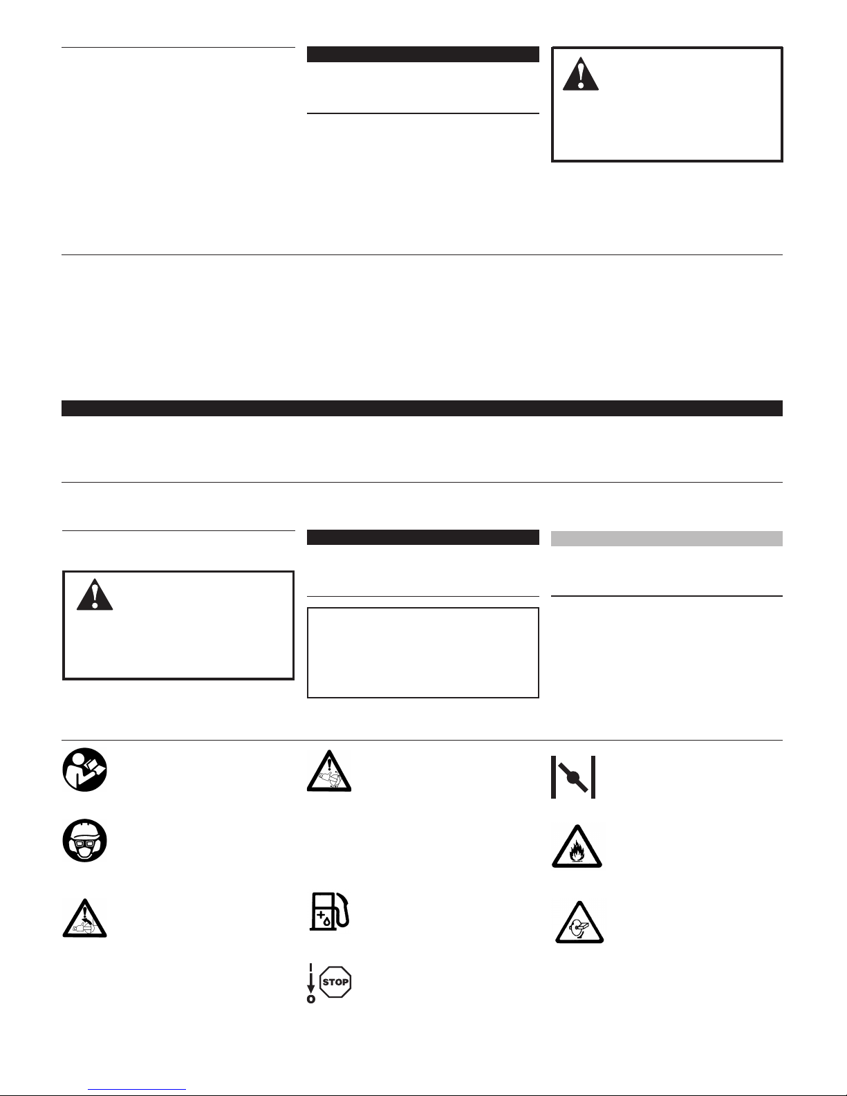
When operating the unit, always
wear snug-tting clothing, safety
gloves, safety non-skid footwear,
hearing protection, a dust-proof
mask, a helmet and goggles. Never
wear oppy clothing, shorts, sandals
or accessories that could become
entangled.
A rst-time operator should obtain
practical instruction from a dealer or an
experienced user before using the unit.
To minimize the risk of sparks igniting
clothing while operating the unit, wear
clothing made of leather, wool, tightly-
woven cotton, or cotton treated with
ame-retardant.
Never use any cut-off wheel that is
not recommended in this manual.
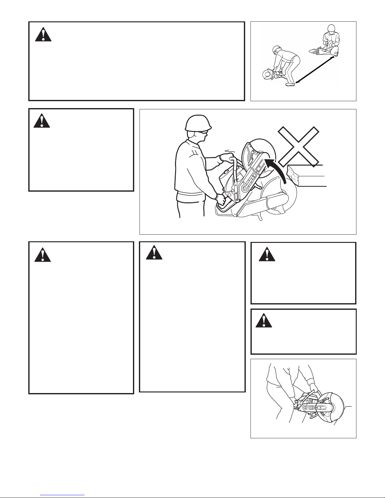
Do not start or operate the unit unless
you have a clear work area and
secure footing.
Do not operate the machine for more
than two hours a day in total. Do not
operate it for more than ten minutes
continuously. Due to vibration,
excessive operation may cause you
white nger disease.
Never smoke or use re near the unit
or its fuel.
Since the mufer and exhaust gas
become very hot, make sure there
are no ammable substances near
the unit.
■
■
■
■
■
■
■
■
Never run the unit if you discover a
fuel leak.
Make sure all the components are
in place and the bolts are securely
fastened.
Make sure the cut-off wheel is
securely fastened and is not
damaged. Never use a cut-off wheel
with cracks, distortion, or one that is
unbalanced.
Make sure the belt tension is properly
adjusted and the wheel guard, belt
guard and clutch cover are securely
assembled.
Always inspect the front handle, rear
handle and wheel guard before use,
and never use the unit if the parts are
damaged.
Before cutting into a material,
familiarize yourself with the risks
associated with dust, fumes, or
mists that may be generated during
operation. Make sure you provide
adequate protection against harmful
emissions. A high-performance
respirator and/or water attachment
may be required.
Do not use the cut-off saw to cut
or disturb asbestos or products
containing or wrapped in asbestos.
If you believe you might be cutting
asbestos, contact your supervisor.
■
■
■
■
■
■
■
Safety Precautions
WARNING!
Before Operation
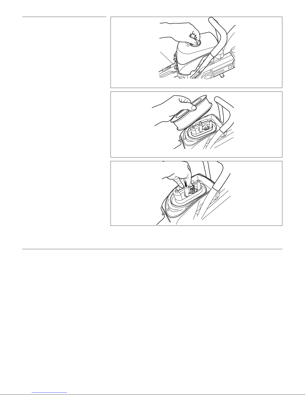
Mixing fuel and engine fueling must
be done outside, and where no other
combustibles are nearby.
Open the fuel cap slowly to release
any possible build-up of pressure.
■
■
Never refuel when the unit is hot.
Allow to cool before refueling.
Never fuel when the engine is
running.
■
■
After fueling, wipe all spilled fuel.
Cutting metal may cause sparks from
the cut-off wheel and may ignite spilled
fuel which could result in serious injury.
■
WARNING!
Fueling the Unit

Always be aware of, and prepared for, kickback.
4
When carrying the unit, make
sure engine and cut-off wheel are
completely stopped.
Carry the unit with the front handle
and with cut-off wheel facing
rearward.
When storing the unit, make sure
the cut-off wheel is removed and
the unit is placed on a secure, dry
place.
Keep the unit away from children.
When storing the unit for more than
a few days, empty the fuel tank
completely.
Store gasoline and mixed fuel in
a closed, dry place and where
combustibles are not nearby.
■
■
■
■
■
■
Safety Precautions (continued)
Figure 1
Start the engine at least 3 meters
from a fueling location.
Start the engine at least 3 meters
away from a fueling location.
When starting the engine, make sure
the cut-off wheel does not touch any
object or ground. As soon as the
engine starts, the cut-off wheel may
begin to rotate.
■
■
Start the engine according to the
instructions in this manual. Start the
engine on a rm, stable surface. Make
sure the area is clear of bystanders.
Starting the engine must be done by
only one person without any assistance.
The cut-off wheel should not rotate at
engine idle. If it does, reduce idle speed.
Never leave the unit running
unattended.
■
■
■
WARNING!
Starting the Engine
Kickback may force the cut-off
wheel up and back toward the
operator lightning-fast.
Kickback can occur whenever
the upper half of the cut-off wheel
touches an object. Never cut an
object using the upper half of the
cut-off wheel.
■
■
WARNING!
Kickback
Figure 2
Always operate below chest level.
Figure 3
The cut-off wheel coasts for a
while after the engine is stopped.
Keep hold of the unit rmly until
the wheel stops completely and
then place it on the ground.
■
Before performing any inspection,
maintenance, repair or cleaning
of the unit, make sure engine
and cut-off wheel are completely
stopped and cooled down.
Inspection and maintenance
operations should be done in a
well ventilated location and where
there are no combustibles nearby.
When replacing parts, always use
Shindaiwa genuine parts. Using
non-Shindaiwa genuine parts may
result in serious injury.
Inspection and maintenance
operations not mentioned in this
manual should be performed by an
authorized Shindaiwa dealer.
■
■
■
■
WARNING!
Stopping the Engine
WARNING!
Inspection and Maintenance
WARNING!
Transport and Storage
WARNING!
This unit must be operated below
chest level. Operating above chest
level may result in serious injury.
■

EC7500.1
Noperformanceguaranteewithout�
usinggenuineShindaiwablades�
No-loadrevolutionspeed:4180min
-1
(rpm)�
Usereinforcedabrasivebladeswith�
maximumuseableperimetervelocityof:�
15,749ft/min.(4800m/min.)
USEONLYGENUINE�
SHINDAIWABLADES
EC7500
Max.bladediameter:12"(305mm)�
Max.bladethickness:0.157"(4.0mm)�
Standardarbor:0.86"(22mm),�
othersavailable;seeowner’smanual
EC7500.18
BELT
DIRECTION
Wheel Guard
Lock Knob
Lock
DECOMPRESSION
VALVE
PRIMER
GASOLINE : OIL
50 : 1 No Fire
Allowed
EC7500 EC7600
4180 min-1
STOP
Free
Rated spindle speed
3800 min-1
Max spindle
speed
3320 min-1
Rated spindle speed
3650 min-1
Max spindle
speed
IMPORTANT!
Make sure all safety and operation
information labels are undamaged
and readable. Immediately replace
damaged or missing safety and
operation information labels, which
are available from your authorized
Shindaiwa dealer.
5
Safety Precautions (continued)
The unit must be held rmly with both
hands, one hand on the rear handle,
the other on the front handle. Never
hold onto any other part of the unit.
When cutting vertically, the unit
should be positioned horizontally
or with the wheel side tilted slightly
down. When cutting horizontally, the
recoil starter-side should face up.
Never impact or apply pressure to
the sides of the cut-off wheel for any
reason.
Maintain rm and stable footing
during operation. Do not overreach.
■
■
■
■
When working in a group, make sure
operators are least 10 meters away
from each other.
If you drop the unit or strike it against
a hard surface, stop the engine
immediately and inspect for damage.
If you discover damage, have it
repaired before you return the unit to
service.
Check the fuel ller cap regularly
during operation to make sure it
remains securely tightened.
If you discover fuel leakage,
immediately stop the engine.
■
■
■
■
Cutting may cause sparks from the
cut-off wheel. Make sure there is no
ammable substances nearby.
Never cut live electrical wires. The
shock you might receive could be
very serious.
Do not touch hot parts
such as the mufer or cylinder. You
could burn yourself severely.
The cut-off wheel gets hot while cutting.
Never touch the wheel immediately after
cutting. You could burn yourself severely.
While the engine is running, never touch
high voltage parts such as the spark
plug cap and plug cord.
■
■
■
■
WARNING!
Operation
Safety Labels
Figure 4

EC7500.18
Figure 5
EC7500.1A
Front
Handle
Cylinder
Cover
Throttle
Trigger
Lockout
Cut-off Wheel
Fuel Filler
Cap
Recoil Starter
Throttle
Trigger
ON/OFF
Switch
Air Cleaner
Cover
Choke
Primer Pump
Carburetor Idle
Adjustment Screw
Wheel Guard
Lock Knob
Belt Guard
Rear
Handle
Clutch Cover
Mufer
Decompression
Valve
6
Engine type................................................................................ 2-cycle, vertical cylinder, air-cooled
Displacement ........................................................................... 73.5 cm3*
Bore x stroke ........................................................................... 2 in. x 1.4 in. /51 x 36 mm
Maximum power output.......................................................... 4.5 hp/3.3 kW
Type of fuel ............................................................................... Unleaded gasoline plus 2-cycle engine oil
(50: 1)
Fuel tank capacity .................................................................... 27.1 oz./800 ml
Carburetor type ........................................................................ Diaphragm
Ignition system ........................................................................ Electronic
Spark plug................................................................................. NGK BPMR7A
Engine starting/stopping........................................................ Toggle switch/recoil starter
Power transmission.................................................................. Automatic centrifugal clutch, V-ribbed belt
Anti-vibration system................................................................ Unified handles with 7-point support
Safety devices............................................................................ Throttle lock-out, wheel guard
Recommended engine idling speed........................................ 2,500 min-1 (RPM)**
Recommended maximum engine idling speed...................... 10,450 min-1 (RPM)**
EC7500 EC7600
Rated spindle speed.................................................................. 3,800 min-1 (RPM) 3,320 min-1 (RPM)
Maximum spindle speed.......................................................... 4,180 min-1 (RPM) 3,650 min-1 (RPM)
Maximum peripheral wheel speed
................................................
67 m/s 68 m/s
Speed reduction ration............................................................. 2.50 : 1 2.87 : 1
Dry weight (without wheel).................................................... 22 lb./10.0 kg 23.1 lb./10.5 kg
Dimensions (L x l x H)............................................................ 29.1 x 8.7 x 14.8 in./740 x 220 x 375 mm
30.1 x 8.7 x 15.4 in./765 x 220 x 390 mm
Maximum cutting depth
Abrasive Wheel................................................................ 12 in. - 4 in./305 mm - 102 mm 14 in. - 5 in./355 mm - 127 mm
Diamond wheel................................................................ 12.6 in. - 4.3 in./320 mm - 109 mm 14.2 in. - 5.1 in./360 mm - 129 mm
Recommended cut-off wheels
Abrasive............................................................................ 12 in./305 mm 14 in./355 mm
Diamond............................................................................ 12.6 in./320 mm 14.2 in./360 mm
Arborsizes.................................................................................. .8 in., .9 in., 1.0 in./ 20 mm, 22 mm and 25.4 mm
Unit Description
Specications
EPA Emission Compliance Period**.................................. Category A
** The EPA emission compliance referred to on the emission compliance label located on the engine, indicates the number of operating hours for which the
engine has been shown to meet Federal emission requirements. Category C = 50 hours (Moderate), B = 125 hours (Intermediate) and A = 300 hours (Extended).
Specifications are subject to change without notice.
* meets or exceeds these specifications and is recommended for all Shindaiwa products.

20 mm
Collar 22mm
Collar 25.4mm
Collar
Snap
Ring
Flange
Collar
Drive
Shaft
7
WARNING!
Use of the incorrect collar
size may lead to wheel failure and unit
failure that could result in serious injury.
Assembly
Figure 6
Instruction
Manual
Engine Unit
Tool Set
Figure 8
Belt Guard
Hex Wrench
Select a cut-off wheel for your work
according to the following chart. Refer
to the wheel manufacturer’s manual for
additional information.
Make sure the ON-OFF switch is Off
and the engine is stopped.
1.
2.
Before assembling, make sure you have
all the components required for a com-
plete unit. This unit consists of the items
shown in Figure 6.
Carefully inspect the engine unit for
damaged or loosen bolts. If you find any
damage or missing items, check with your
Shindaiwa dealer.
IMPORTANT!
This unit is equipped with a .87 in./22 mm
wheel collar. Wheel adapters for .78 in./20
mm and 1.0 in./25.4 mm cut-off wheels are
located in the tool set. Before mounting a
wheel, determine its arbor diameter. If it is
necessary to replace the collar, remove the
snap ring on the arbor, install the correct size
arbor collar, and then replace the snap ring.
Place cut-off wheel so the inner bore is
properly set onto the collar.
5.
Figure 9
Outer Flange
Bolt
Tighten
Loosen
Replace outer flange and bolt, and then,
while holding hex wrench in the hole in
belt guard, tighten the bolt with wrench.
Make sure the cut-off wheel is securely
fastened. Spin the wheel to make sure it
does not wobble.
6.
7.
WARNING!
Using an inappropriate cut-off
wheel may cause the wheel to break
and may result in serious injury.
Recommended cut-off wheels
Internal
diameter
.79 in., .87 in., 1.0 in.
20 mm, 22 mm, 25,4 mm
Discs for
model
EC7500 EC7600
Abrasive: outer diameter
12 in./305 mm
outer diameter
14 in./355 mm
Diamond:
outer diameter
12.6 in./320 mm
outer diameter
14.2 in./360 mm
Prior to assembly
Mounting the Cut-off Wheel
Insert a hex wrench into the hole in the
belt guard to prevent the arbor from
turning. See Figure 8.
Loosen bolt with the wrench and remove
bolt and outer flange. See Figure 9.
3.
4.
Figure 7

8
NEVER smoke or light res near the
engine.
ALWAYS stop the engine and allow it
to cool before refueling.
ALWAYS Wipe all spilled fuel and move
at least 3 meters from the fueling point
and source before starting.
ALWAYS inspect the unit for fuel
leaks before each use. During each
rell, check that no fuel leaks from
around the fuel cap and/or fuel tank.
If fuel leaks are evident, stop using
the unit immediately. Fuel leaks must
be repaired before using the unit.
ALWAYS move the unit at least 3
meters away from a fuel storage area
or other readily ammable materials
before starting the engine.
NEVER place ammable material
close to the engine mufer.
NEVER operate the engine without
the mufer and spark arrester screen
in place.
Mixing fuel
Place the unit on a flat, level surface.
Clear any dirt or other debris from
around the fuel filler cap.
Remove the fuel cap, and fill the tank
with clean, fresh fuel.
Reinstall the fuel filler cap and tighten
firmly.
1.
2.
3.
4.
Filling the fuel tank
CAUTION!
This engine is designed to operate
on a 50:1 mixture consisting of
unleaded gasoline and ISO-L-EGD
or JASO FC class 2-cycle mixing oil
only. Use of non-approved mixing
oils can lead to excessive carbon
deposits.
CAUTION!
Never use any type of gasoline
containing more than 10% alcohol
by volume! Some types of gasoline
contain alcohol as an oxygenate.
Oxygenated gasoline may cause
increased operating temperatures.
Under certain conditions, alcohol-
based gasoline may also reduce
the lubricating qualities of some
2-cycle mixing oils.
Generic oils and some outboard
oils may not be intended for use
in high-performance two-cycle
engines, and should never be used
in your Shindaiwa engine.
■
■
Use only fresh, clean unleaded gasoline
with a pump octane of 87 or higher.
Mix all fuel with a 2-cycle air-cooled
mixing oil that meets or exceeds ISO-
L-EGD and/or JASO FC classified oils
at 50:1 gasoline/oil ratio.
■
■
Examples of 50:1 mixing quantities
WARNING!
Minimize the Risk of Fire
IMPORTANT
Mix only enough fuel for your immediate
needs! If fuel must be stored longer than
30 days, it should first be treated with a
fuel stabilizer such as STA-BIL™.
Gasoline 2-cycle mixing oil
liters milliliters
2.5 - 1
50 ml
5 - 1 100 ml
10 - 1 200 ml
20 - 1 400 ml

9
WARNING!
Keep well away from re!
Push the decompression valve In.
Pull the choke all the way out (choke
closed). The throttle will automatically
be set to fast idle. See Figure 10.
Place the unit on firm ground.
Secure the unit by placing your right
foot inside the rear handle and your left
hand on the front handle. See Figure 11.
3.
4.
5.
6.
Figure 11
Before starting the engine, place
the unit on a clean, level surface.
Make sure you have good secure
footing and always keep a rm grip
on the unit.
Move at least 9.8 ft./3 meters
away from the fueling site before
starting the engine.
Make sure the cut-off wheel is well
clear of obstacles. The cut-off wheel
may rotate when the engine starts.
Keep bystanders well away.
Never start the engine without a
cut-off wheel installed.
■
■
■
■
■
Starting a cold engine
Figure 10
Primer
Pump
Choke
Turn the on-off switch On.
Depress the primer pump a few times
repeatedly until the primer pump is
almost filled with fuel. See Figure 10.
1.
2.
When the engine fires, push the choke
in to its original position (choke open).
If the engine does not continue to run,
pull the recoil again.
As the engine starts, clear excess fuel
from the combustion chamber by rev-
ving the engine several times.
Let the engine run at idle speed for 2-3
minutes to warm up.
9.
10.
11.
12.
CAUTION!
The recoil starter can be damaged
by abuse.
Never pull the starter cord to its full
length.
Always engage the starter before
cranking the engine.
Always rewind the starter cord
slowly. Do not just let go of the cord.
■
■
■
■
IMPORTANT!
The throttle trigger can not be moved
without first depressing the lockout lever.
Operating the throttle will automatically
disengage the fast idle setting.
WARNING!
Grip the recoil starter handle with your
right hand, pull the starter cord slowly
until you feel the starter engage, then…
…start the engine by pulling the starter
cord upward rapidly.
7.
8.
Turn the on-off switch On.
Push the decompression valve in.
Pull the choke all the way out and push
it back to the original position (choke
open). The throttle is automatically set
at a fast idle position.
1.
2.
3.
Starting the engine
If the engine doesn’t start
WARNING!
The cut-off wheel must not
rotate at idle speed. If it rotates,
reduce idle speed by adjusting the
idle adjust screw.
Follow Steps 5 though 12, Starting a
Cold Engine.
4.
If the engine fails to start, repeat the
appropriate starting procedure for a cold
or warm engine.
Starting a warm engine

10
Pull the choke all way out.
Unscrew the knob on the cleaner cover
and remove the cleaner cover. See
Figure 12.
Unscrew the two bolts securing the
filter element, remove the filter element.
See Figure 13.
Remove the plug cap and disconnect the
spark plug by using the plug wrench.
See Figure 14. Check to see if the spark
plug electrode is fuel-soaked.
If the spark plug is wet, dry it com-
pletely. Clear excess fuel from the
combustion chamber by cranking the
engine several times with the spark plug
is removed.
Reassemble the spark plug, plug cap,
filter and cleaner cover.
Follow the appropriate starting proce-
dure described above.
If the spark plug is dry, fuel is likely
not being supplied to the combustion
chamber properly.
Check the fuel filter and carburetor. Refer
to the Inspection and Maintenance Section
.
Refer to the Troubleshooting Section.
If the engine still does not start, contact
your Shindaiwa dealer.
1.
2.
3.
4.
5.
6.
7.
8.
■
■
■
Figure 14
Let the engine run at idle speed for 2-3
minutes, then turn the on-off switch Off.
If the engine still does not start...
Stopping the Engine
Starting the engine (continued)
Figure 13
Figure 12
Choke

11
WARNING!
When using the cut-off saw,
the wheel guard must be securely
in position as a protection against a
broken wheel. If the wheel guard is
not in place, a broken wheel could
project fragments at high speed
and strike you or others, possibly
resulting in serious injury.
This unit is designed to be operated for
either dry or wet cutting. A water dust-
suppression kit is available for this unit
but is not supplied in the unit packaging.
Please refer to the assembly and operating
instructions supplied with the water dust-
suppression kit.
Operation
This unit performs most efficiently when
cutting between 8,500 and 9,500 min-1
(rpm). While running the engine at full
throttle, apply slight pressure to the cut-
off wheel against an object so that engine
speed stays at 8,500–9,500 min-1 (rpm).
Too much pressure to the wheel will lower
wheel speed, reducing cutting efficiency
considerably.
Figure 15
Wheel Guard
Lock Knob
Wheel Guard
Locked
Wheel Guard
Free
WARNING!
Never permit bystanders or animals
near the unit when starting or
operating the unit.
Be aware of kickback! Kickback
may force the cut-off wheel up and
back toward the operator lightning-
fast. Kickback can occur whenever
■
■
the upper half of the cut-off wheel
touches an object. Never cut an
object using the upper-half of the
cut-off wheel.
When operating, always wear
snug-tting clothing, safety gloves,
safety non-skid footwear, hearing
protection, a dust-proof mask, a
helmet and goggles.
■
Adjust the position of the wheel guard
so that fragments will not fly toward you
if the wheel fractures. To reposition the
wheel guard, loosen the lock knob (coun-
terclockwise). When the wheel guard is
positioned correctly, securely tighten the
lock knob. See Figure 15.
Make sure you have a clear work area
and secure footing.
Position the cut-off wheel vertically to
an object. Start cutting at a low speed
and then gradually accelerate the speed.
1.
2.
Cutting
Wet or Dry Operation
Adjusting Wheel Guard Angle

12
Figure 20
Back off tension screw another 4-5 turns
so that adequate clearance is achieved
where the tension screw contacts the
mount when the mount is turned over.
See Figure 17.
2.
6mm Socket-
Head Bolts
Figure 21
Reversing cutting head for ush cutting operations
WARNING!
Before performing any work
on the cut-off saw, make sure the
engine is stopped and the ignition
switch is OFF.
NOTE:
For units equipped with a water kit, loosen
the (2) water nozzles and disconnect the
main water line from the double nozzle.
Remove the cutting wheel (Refer to
Section Mounting the Cut-off Wheel).
Using a Phillips screwdriver, loosen the
tension screw until the tension indicator
is all the way to the front of the scale.
See Figure 16.
1.
Figure 16
Tension Screw Tension
Indicator
Remove Cutting Wheel
Loosen Two
Bolts
Using a 6mm hex wrench, remove the
two belt guard bolts and slide the belt
guard forward to remove. See Figure 18.
3.
Figure 17
Mount
Tension Screw
Figure 19
Making sure that the drive belt is fully
engaged in the drive pulleys, slide the
belt cover on and install the two socket-
head bolts into the left-hand side of the
mounting surface only until the bolts
bottom on the belt cover. See Figure 20.
5.
Belt Guard
Figure 18
Remove the blade mount from the
mounting surface and rotate the blade
mount 1800, then remount to the right
hand side of mounting surface
. See
Figure 19.
4.
6mm Socket-
Head Bolts
Operating (continued)
Adjust the tension screw until the
tension indicator is in the middle of the
scale. See Figure 21.
6.
Tighten the two mounting bolts securely.
Reconnect the main water line, adjust
and retighten water nozzles (if equipped
with a water kit).
Reinstall the cutting wheel. Back off
tension screw another 4-5 turns so that
adequate clearance is achieved where the
tension screw contacts the mount when the
mount is turned over. See Figure 17.
7.
8.
9.

EC7500.48
Pre-lter
13
Inspection and Maintenance
Inspection and Maintenance Requirements
IMPORTANT!
MAINTENANCE, REPLACEMENT,
OR REPAIR OF EMISSION CONTROL
DEVICES AND SYSTEM MAY BE
PERFORMED BY ANY REPAIR
ESTABLISHMENT OR INDIVIDUAL.
HOWEVER, WARRANTY REPAIRS
MUST BE PERFORMED BY A DEALER
OR SERVICE CENTER AUTHORIZED
BY SHINDAIWA CORPORATION
AND USE OF PARTS THAT ARE NOT
EQUIVALENT IN PERFORMANCE AND
DURABILITY TO AUTHORIZED PARTS
MAY IMPAIR THE EFFECTIVENESS OF
THE EMISSION CONTROL SYSTEM
AND MAY HAVE A BEARING ON THE
OUTCOME OF THE WARRANTY CLAIM.
Dust in the air cleaner will affect engine
life. The air filter must be cleaned every
time you start operating.
Clean the air filter once a day and
replace the filter every 20 hours of
operation according to the following
procedures. See Figure 22.
Pull the choke lever out so that dust will
not enter the carburetor.
Unscrew the knob on the cleaner cover
and remove the cleaner cover and filter.
Remove the pre-filter from the filter.
clean the pre-filter with soap and water
and let dry.
If compressed air is available, blow air
from inside the filter to remove dust. If
compressed air is not available, remove
dust by gently tapping the element on a
hard surface.
Replace the pre-filter onto the filter and
reassemble them into the filter housing.
Make sure both filter bolts are securely
tightened.
1.
2.
3.
4.
5.
6.
Cleaning the Air Cleaner
Remove the Filter and
Pre-lter
Figure 22
Unscrew the
Knob
Choke
Filter
WARNING!
Inspection and maintenance
should be done in a well ventilated
place and where there is no risk of re.
IMPORTANT!
When cleaning the filter, the filter housing
and the inside of the cleaner cover should
also be cleaned.
Item What to do Daily Weekly Monthly As Required
Air cleaner Clean ■
Cut-off wheel Clean and
sharpen ■
Bolts/screws Check and
retighten ■
Fuel cap Check for leakage ■
Fuel tank Check for leakage ■
Wheel guard Check function ■
Clutch bearing Grease ■
Belt Check and adjust ■
Spark plug Check and clean ■
Cylinder ns Clean ■
Fuel lter Clean ■
Carburetor Adjust ■
Reinstall the cleaner cover and make
sure the knob is securely tightened.
7.

14
To adjust idle speed, turn the Idle Adjust
Screw with a screwdriver. See Figure 23.
Turn clockwise to increase idle speed.
Adjust idle speed so the cut-off wheel does
not rotate at idle.
Recommended idle speed: 2,200–2,600
min-1 (rpm)
1.
Figure 23
Adjusting the Carburetor WARNING!
When adjusting the carburetor,
keep bystanders well away, and make
sure the cut-off wheel is clear of any
interference because the wheel may
rotate during carburetor adjustment.
If the engine becomes hard to start or if
idle speed is unstable, inspect the spark
plug according to the following procedures.
Remove the spark plug. See the section
"If the Engine Does Not Start… "
Clean the electrode with a wire brush.
If necessary, adjust the electrode gap.
The gap should be .024 in./0.6mm.
See Figure 24.
1.
2.
Figure 24
.024 in./0.6mm
WARNING!
Before cleaning cylinder
ns, make sure the engine is cold.
Inspection and Maintenance (continued)
It is not necessary to adjust the carburetor
when the unit is new. Adjust the carbure-
tor only when you are sure it is necessary
due to differences in working conditions
such as atmospheric pressure or tempera-
ture, or change in unit conditions after
more than 10 hours of use.
If you are unfamiliar with carburetor
adjustment techniques, ask your dealer
for advice.
Adjust the carburetor in accordance with
the following procedure.
Prior to adjusting, clean the air filter as
described on the previous page and then
run the engine for a few of minutes at idle
speed to warm up the engine.
1.
Adjusting Idle Speed
High and Low Speed Needle
Spark Plug Maintenance
Cleaning Cylinder Fins
The high and low speed needle is fixed
and cannot be adjusted.
Dust and debris may accumulate between
the cylinder fins and can lead to engine
overheating. In order to maintain efficient
service, cylinder fins should be cleaned
once every month.
Checking the Drive Belt
The transmission belt tends to loosen
and wear after a period of operation and
should be checked and adjusted regularly
according the following procedures. If the
belt is worn, torn, cracked, scratched or
otherwise damaged, replace it with a new
one immediately.

15
Loosen the two bolts in the belt guard
by one turn. See Figure 25.
Turn the tension screw so the washer
aligns with the mark on the clutch
cover.
Tighten the two bolts in the belt guard.
1.
2.
3.
Figure 25
Clutch Cover
Bolts
Mark
Belt Guard
Washer
Tension
Screw
Adjusting Belt Tension
Inspection and Maintenance (continued)
Figure 26
Tension
Screw
Clutch
Cover
Bolt
Belt Guard
Slide
forward to
remove
Figure 27
Replacing the Drive Belt
Loosen the tension screw. Loosen the
two bolts on the belt guard and remove
the belt guard by sliding it to the right.
See Figure 26.
Loosen the two bolts in the clutch cover
and remove the clutch cover.
Replace the old belt with a new one.
Reassemble the clutch cover and the
belt guard and adjust the belt tension.
Figure 27 illustrates the components.
1.
2.
3.
4.
Always check the condition of the cut-off
wheel before starting the engine. Make
sure there are no breaks, cracks or warps.
See Figure 28.
A faulty wheel must be replaced with
a new one!
The tips of a diamond wheel should be
sharpened regularly to maintain cutting
efficiency.
Figure 28
Cracks
Missing Tips
Worn Tips
Distortion or Warps
Checking the Cut-off Wheel
WARNING!
Never use a wheel which
has breakage, cracks or distortion.
The wheel may break while operat-
ing and may result in serious injury.

EC7500.42
16
WARNING!
Make sure the replacement
cut-off wheel rpm rating is greater
than the speed indicated on the
wheel guard label.
WARNING!
Using the wrong size collar
may lead to failure of the wheel or the
unit and could result in serious injury.
Make sure the ignition switch is Off and
the engine is stopped.
Insert a 6mm hex wrench into the hole
in the belt guard to prevent the drive
shaft from turning. See Figure 29.
Loosen the outer flange bolt with the
wrench and remove the bolt and outer
flange.
Before mounting a cut-off wheel, deter-
mine its arbor diameter. If necessary,
remove the snap ring from the arbor,
install the correct collar, then re-install
the snap ring.
1.
2.
3.
4.
Figure 29
Outer
Flange
Remove the old wheel and install the
new one. Make sure the inner bore is
properly set onto the collar.
5.
Belt Guard
Hex Wrench
Outer
Flange
Bolt
Wrench
Tighten
Loosen
CAUTION!
Make sure the rotating direction of
wheel corresponds to the one indicated
on the wheel guard. Make sure there is
no dust around the outer ange.
Label Showing
Direction of
Rotation
Label Showing Rated
and Maximum Spindle
Speed
Wheel Guard
Diamond
Wheel
Replacing the Cut-off Wheel
Figure 31
Hooked Wire
Fuel Filler
Cap
Fuel Filter
Inspection and Maintenance (continued)
Replacing the Cut-off Wheel
Replace the outer flange and bolt, then
holding the hex wrench in the hole of
the belt guard, tighten the bolt with the
wrench.
Make sure the cut-off wheel is securely
fastened and does not wobble.
6.
7.
Figure 30
While running the engine at low speed,
make about 10 passes at cutting a concrete
block or a soft brick. Keep the block
watered while sharpening.
Sharpening a Diamond Cut-off Wheel
WARNING!
KEEP AWAY FROM FIRE
OR EXCESS HEAT!
CAUTION!
Make sure the fuel line is not pierced
by the hooked wire. The fuel line can
be easily damaged.
Remove the fuel filler cap.
Take the filter out from the fuel opening
by using a hooked wire. If the filter is
hard and clogged with debris, replace it
with a new one. See Figure 31.
1.
2.
Checking the Fuel Filter
Put the filter back into the fuel tank.
Make sure the fuel tube is not bent and
the filter stays at the bottom of the tank.
Put the fuel filler cap back and tighten it
securely.
3.
4.

Cover
Screws
Direction
Arrows
Cover
Front of
Mufer
Arrester
Screen
CAUTION!
Carbon deposits in the combustion
chamber or exhaust port cannot
be removed in the eld. For decar-
bonization, return the unit to your
Shindaiwa dealer.
CAUTION!
When installing the spark arrester
cover make sure the arrows are
directed to the front of the mufer. If
the spark arrester cover is installed
incorrectly, the hot exhaust gases will
be directed into the unit and may cause
heat damage to surrounding parts.
Hard starting or a gradual loss of perfor-
mance can be caused by carbon deposits
lodged in the muffler’s spark arrester screen.
To service or replace the spark arrester,
remove the two cover screws and cover,
then remove the screen. Clean the screen
with a small wire brush. Replace if damaged.
Reinstall the screen and cover with the
arrows directed to the front of the muffler.
Spark Arrester Maintenance
17
Grease Gun
Figure 32
Grease the clutch bearing every 20 hours
of operation. Squeezing a grease gun
three times will deliver an appropriate
amount of grease. See Figure 32.
Inspection and Maintenance (continued)
Lubricating the Clutch Bearing
Whenever the unit will not be used for 30
days or longer, use the following procedures
to prepare if for storage:
Clean external parts thoroughly.
Drain all the fuel from the carburetor
and the fuel tank.
■
■
Long Term Storage
CAUTION!
Gasoline stored in the carburetor for
extended periods can cause hard start-
ing and could also lead to increased
service and maintenance costs.
IMPORTANT!
All stored fuels should be stabilized with a
fuel stabilizer such as StaBil™.
To remove the remaining fuel from the
fuel lines and carburetor and with the fuel
drained from the fuel tank…
Prime the primer bulb until no more
fuel passes through.
Start the engine and idle until it stops
running.
Repeat Steps 1 and 2 until the engine
will no longer start.
1.
2.
3.
Remove the spark plug and put a small
amount of 2-cycle mixing oil (1-2 cm3)
into the cylinder through the spark
plug hole. Slowly pull the recoil starter
2 or 3 times so oil will evenly coat the
interior of the engine. Reinstall the
spark plug.
Before storing the unit, repair or
replace any worn or damaged parts.
Remove the air cleaner element from
the carburetor and clean it as described
in "Cleaning the Air Cleaner", then
reassemble the element.
Clean the exterior of the unit thoroughly.
Store the unit is a clean, dust-free area.
■
■
■
■
■
Figure 33

18
If the above inspections and maintenance procedures do not correct the problem,
contact your Shindaiwa dealer for assistance.
Troubleshooting Guide
PROBLEM
Engine does not start
Cutting performance is poor
Is spark plug wet?
Is spark plug dry?
Make sure the choke is pushed in fully.
Make sure air cleaner element is clean.
Make sure carburetor is properly adjusted.
Make sure the cut-off wheel is appropriate to your work.
Make sure the diamond wheel is sharp.
Remove the spark plug.
Make sure the drive belt is properly tightened.
Dry the spark plug. Pull the recoil
starter several times to remove fuel
from the cylinder. Restart.
Make sure the fuel tank contains fresh, clean fuel.
Replace fuel filter.
PROBLEM

19
Shindaiwa Corporation warrants to the initial purchaser and each
subsequent owner, that this utility equipment engine (herein
engine) is designed, built and equipped to conform at the time of
initial sale, to all applicable regulations of the U.S. Environmental
Protection Agency (EPA), and that the engine is free of defects in
materials and workmanship that would cause this engine to fail
to conform with EPA regulations during its warranty period. This
emission warranty is applicable in all States, except the State of
California.
For parts listed under PARTS COVERED, the dealer authorized by
Shindaiwa Corporation will, at no cost to you, make the necessary
diagnosis, repair, or replacement of any defective emission-related
component to ensure that the engine complies with applicable U.S.
EPA regulations.
MANUFACTURERS WARRANTY COVERAGE
When sold within the U.S., this engine’s emission control system is
warranted for a period of two (2) years from the date this product is first
delivered to the original retail purchaser.
OWNER’S WARRANTY RESPONSIBILITIES
As the engine owner, you are responsible for the performance of
the required maintenance listed in your owner’s manual. Shindaiwa
Corporation recommends that you retain all receipts covering maintenance
on your engine, but Shindaiwa Corporation cannot deny a warranty claim
solely for the lack of receipts or for your failure to ensure the performance
of all scheduled maintenance.
As the engine owner, you should however be aware that Shindaiwa
Corporation may deny your warranty coverage if your engine or a part
has failed due to abuse, neglect, improper maintenance or unapproved
modifications.
You are responsible for presenting your engine to the nearest dealer
authorized by Shindaiwa Corporation when a problem exists.
If your Shindaiwa Dealer is unable to answer questions regarding your
warranty rights and responsibilities, you should then contact your
Shindaiwa Distributor.
For the name and telephone number of the Shindaiwa Distributor in your
area, please call Shindaiwa Inc. at (503) 692-3070 between the hours of 8:00
AM and 5:00 PM Pacific Standard Time.
PARTS COVERED
Listed below are the parts covered by the Federal Emission Design
and Defect Warranty. Some parts listed below may require scheduled
maintenance and are warranted up to the first scheduled replacement of
that part. The warranted parts include:
1. Carburetor Internal Components
• Valve Assembly-throttle, Jet, Metering Diaphragm
2. Ignition System Components
• Ignition Coil
• Flywheel Rotor
The emission control system for your particular Shindaiwa engine may also
include certain related hoses and connectors.
The following statement only applies to United States and its territories
Shindaiwa Corporation
Federal Emission Design And Defect Limited Warranty
Utility And Lawn And Garden Engines
LIMITATIONS
The Federal Emission Design and Defect Warranty shall not cover any of
the following:
(a) conditions resulting from tampering, misuse, improper adjustment
(unless they were made by the dealer or service center authorized
by Shindaiwa Corporation during a warranty repair), alteration,
accident, failure to use the recommended fuel and oil, or not
performing required maintenance services,
(b) the replacement parts used for required maintenance services,
(c) consequential parts used for required maintenance services,
(d) diagnosis and inspection fees that do not result in eligible warranty
service being performed, and
(e) any non-authorized replacement part, or malfunction of authorized
parts due to use of non-authorized parts.
MAINTENANCE AND REPAIR REQUIREMENTS
You are responsible for the proper use and maintenance of the engine.
You should keep all receipts and maintenance records covering the
performance of regular maintenance in the event questions arise.
These receipts and maintenance records should be transferred to each
subsequent owner of the engine. Shindaiwa Corporation reserves the right
to deny warranty coverage if the owner has not properly maintained the
engine. Shindaiwa Corporation will not deny warranty repairs, however,
solely because of the lack of repair, maintenance or failure to keep
maintenance records.
MAINTENANCE, REPLACEMENT OR REPAIR OF EMISSION CONTROL
DEVICES AND SYSTEMS MAY BE PERFORMED BY ANY REPAIR
ESTABLISHMENT OR INDIVIDUAL; HOWEVER, WARRANTY REPAIRS
MUSTBEPERFORMEDBYADEALERORSERVICECENTERAUTHORIZED
BY SHINDAIWA CORPORATION THE USE OF PARTS THAT ARE NOT
EQUIVALENT IN PERFORMANCE AND DURABILITY TO AUTHORIZED
PARTSMAYIMPAIRTHEEFFECTIVENESSOFTHEEMISSIONCONTROL
SYSTEM AND MAY HAVE A BEARING ON THE OUTCOME OF A
WARRANTY CLAIM.
If other than the parts authorized by Shindaiwa Corporation are used
for maintenance replacements or for the repair of components affecting
emission control, you should assure yourself that such parts are warranted
by their manufacturer to be equivalent to the parts authorized by Shindaiwa
Corporation in their performance and durability.
OBTAINING WARRANTY SERVICE
All repairs qualifying under this limited warranty must be performed by a
dealer authorized by Shindaiwa Corporation
If any emission-related part is found defective during the warranty period,
it is your responsibility to present the product to an authorized Shindaiwa
dealer. Bring your sales receipts showing the date of purchase for this
engine. The dealer authorized by Shindaiwa Corporation will perform
the necessary repairs or adjustments within a reasonable amount of time
and furnish you with a copy of the repair order. All parts and accessories
replaced under this warranty become the property of Shindaiwa
Corporation
To locate an authorized Shindaiwa dealer near you, contact your Shindaiwa
Distributor. For the name and telephone number of the Shindaiwa
Distributor in your area, please call Shindaiwa Inc. at (503) 692-3070
between the hours of 8:00 AM and 5:00 PM Pacific Standard Time.
THIS WARRANTY IS ADMINISTERED BY
Shindaiwa Inc.
11975 S.W. Herman Rd.
Tualatin OR. 97062
(503) 692-3070

Shindaiwa Inc.
11975 SW Herman Road
Tualatin, Oregon 97062
Telephone 503-692-3070
Fax 503-692-6696
www.shindaiwa.com
Shindaiwa Corporation
6-2-11 Ozuka-Nishi
Asaminami-Ku, Hiroshima
731-3167, Japan
Telephone 81-82-849-2220
Fax 81-82-849-2481
©2007 Shindaiwa Inc.
Part Number 82044
Shindaiwa is a registered trademark of
Shindaiwa Inc.
NOTES
Other manuals for EC7500
2
This manual suits for next models
1
Table of contents
Other Shindaiwa Saw manuals

Shindaiwa
Shindaiwa RC45 User manual

Shindaiwa
Shindaiwa 68002-94310 Owner's manual

Shindaiwa
Shindaiwa 402s User manual

Shindaiwa
Shindaiwa EC741s User manual

Shindaiwa
Shindaiwa EC7500 User manual

Shindaiwa
Shindaiwa 68006-94310 Owner's manual

Shindaiwa
Shindaiwa 490 Owner's manual

Shindaiwa
Shindaiwa EC7600W User manual

Shindaiwa
Shindaiwa 340s User manual

Shindaiwa
Shindaiwa 446s Owner's manual