Shinerich SRPHN02 User manual
Manual,Instructions & Parts List
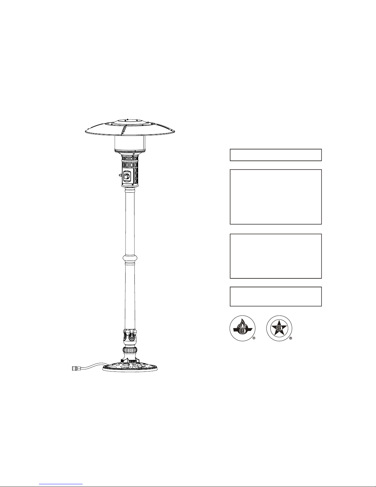
PATIO HEATER
FOR YOUR SAFETY
If you smellgas:
1. Shut off gas tothe appliance.
2. Extinguish anyopen flame.
3. If odorcontinues ,immediately
call gas supplier.
FOR YOUR SAFETY
Do not storeor use gasolineor
other flammable vaporsor liquids
in the vicinityof this orany other
appliance.
WARNING: For Outdoor Use Only.
CAUTION: Retain the instructions
for future use.
Natural Gas
CERTIFIED
I
S
G
E
N
D
C
D
E
E
R
I
T
F
I
Model No.:SRPHN02
Master Contract No.:217109
Customer Item No.:PTHC38NK
2
TOOLS AND PARTS NEEDED FOR ASSEMBLY
TOOLS AND PARTS NEEDED FOR ASSEMBLY
TOOLS NEEDED:
7/16 Wrench
3/8 Open End Wrench
Adjustable Opening Wrench, 8 Long
Philips Head Screwdriver
Leak Detection Solution ( Instructions how to make solution are included in Step 10 )
For questions, replacement parts, service help, or other assistance, please
call SHINERICH at: 86- 755-26930633 or local Shinerich dealer .
WARNING
For outdoor use only.
The unit shouldbe secured ormoved indoors
if winds exceed35 km/h.
Storage indoors ispermissible only ifthe
natural gas isdisconnected.
WARNING: Improper installation,
adjustment, alteration, serviceor
maintenance can causeinjury, death or
property damage.
Read the installation,operating and
maintenance instructions thoroughly
before installing orservicing
this equipment.

3
PARTS
4 Reflector Cap
1
2
3
4
5
1 Centre Reflector Cap
1 Head Assembly
18 6mm Washers
4 8mm Washers
4 M8 Nuts
6
7
8
11
12
9
10
13
1 Mid Post
1 Lower Post
1 Upper Post
15 M6 Nuts
4 8mm Spring Washers
1 Base
4 M8 x55 Bolts
14
15
12 M6x10 Bolts
3 M6x70 doublepointed bolts
8
11 12
10
13
7
9
12
13
2
15
15
1
3
16
14
14
4
5
6
7
911
10
8
16 1 Gas Hose

4
PRECAUTIONS
Do not paint radiant screen, control panel or top canopy
reflector.
Young children should be carefully supervised when they
are in the area of the heater.
Clothing or other flammable material should not be hung
from the heater, or placed on or near the heater.
Keep the appliance area clear of combustible materials
such as gasoline and other flammable vapors and liquids.
Do not obstruct the flow of combustion and ventilation air.
NOTE: PLEASE READ THE FOLLOWING SAFETY RULES
All leak tests should be done with a soapy solution. NEVER
USE AN OPEN FLAME TO CHECK FOR LEAKS.
The natural gashose assembly shallbe located outof
pathways where peoplemay trip overit or inareas
where the hosewill not besubject to accidentaldamage.
Children and adultsshould be awareof the hazardsof high
surface temperature andshall stay awayto avoid burnsor
clothing ignition.
Do not use the heater in an explosive atmosphere.
Keep the heater away from areas where gasoline or other
flammable liquids or vapors are stored.
Do not clean the heater with cleaners that are combustible
or corrosive.
The appliance shallnot be usedin basements orbelow
ground level.
It must alwaysbe placed ona solid andlevel surface.
Read the instructionsbefore use.
This appliance mustbe installed in
accordance with suchregulations as
are in force.
This appliance mustonly be usedoutdoors.
Using this productin an enclosedarea may cause
injury, death or propertydamage.
WARNING
DISCONNECT Natural Gas beforemoving the heater.
Do not attemptto alter unitin any manner.
EXAMPLE: using theheater without thetop canopy
reflector or radiantscreen.
Do not shortenthe burner postassembly.
Always assure there is ample fresh air ventilation.
For outdoor use ONLY.
The installation offixed appliances shallonly be carriedout
by competent personsand be inaccordance with localcodes
or in theabsence of localcodes, with thenational fuel gascode
ANSI Z223.1 in theUSA orthe CSAB149.1 natural gasand
propane installation codein Canada. The manifold pressureand
minimum inlet supplypressure is 7.0inches water column.
The maximum supplypressure is 10.5inches water column.
Prior to use,check for damagedparts such asgas hoses,
natural gas pipe,pilot or burner.
The appliance andits individual shutoff valve must be
disconnected from thegas supply pipingsystem during any
pressure testing ofthat system attest pressures inexcess
of 0.5 PSIG(3.5 KPA).
The appliance mustbe isolated fromthe gas supplypiping
system by closingits individual manualshut off valve during
any pressure testingof the gassupply piping systemat test
pressures equal toor less than0.5 PSIG (3.5KPA).
Warning: This appliance requires a gashose and natural
gas pipe, checkwith your gassupplier and orproduct supplier.
Regularly check thegas hose andnatural gas pipe,
if necessary, replace thegas hose ornatural gas pipe.
At least once a year,the unit should be inspected for the
presence of spiders, spider webs or other insects. Check the
heater immediately if any of the following exist:
1. The smell of gasin conjunction withextreme yellow
colored tips ofthe burner flames.
2. The heater does notreach temperature.
3. The burner makes poppingnoise during use(a slight
popping noise isnormal when theburner is extinguished
after using).
The natural gasshould be turnedoff when the heater is
not in use.
Installation and repairshould be doneby a qualified
service person. The heater shouldbe inspected before
use and cleaningmay be requiredat least oncea year,or as
necessary. It is imperativethat control compartment,burner
and circulating airpassageways of theheater be keptclean.
ASSEMBLY FOR LIGHT SYSTEM
WARNING:
TO BE INSTALLED ONLY BY AN
AUTHORISED PERSON
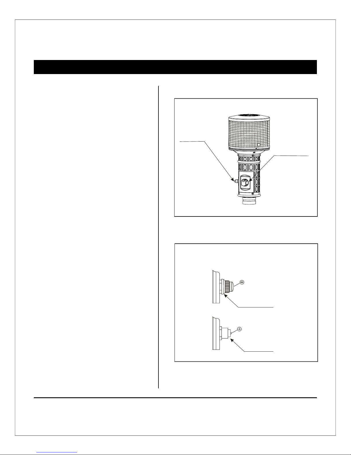
Instruction For Battery Installing
Upon first timeuse of theproduct,please remove the
ignition button andinstall anAA batteryas indicated.
Ignition button
Replace Battery
Control knob
Ignition button
AA battery
5

6
ASSEMBLY
NOTE: Assembly of this heater requires
basic mechanical skills. Proper assembly
is the responsibility of the installer.
Step 1
Turn the mid post clockwise to the
Step 2
Step 1 ----Assembly for lowerpost
Step 2 ----Attach mid postto lower post
6
6
7
9
11
10
8
5
Attach lower post to base
Place the lower post on the top of
base.Then connect them
using 4pcs M8*55 bolts,4pcs 8mm
washers,4pcs 8mm spring washers
and 4pcs M8 nuts
Lower post asillustrated until tighten
them securely.

7
ASSEMBLY
NOTE: Assembly of this heater requires
basic mechanical skills. Proper assembly
is the responsibility of the installer.
Step 4 ---- Attach HeadAssembly to Post
Load head assemblyby inserting gashose
into post.
Step 4
Step 3 ----Attach upper postto mid post
Turn theupper post clockwiseto the
mid post asillustrated until tighten
them securely.
Step 3
4
5
3
4
Turn the head assembly clockwise to
the upper post as illustrated until
tighten them securely.

8
ASSEMBLY
Step 5
Step 5 ----
Route hose throughopening
in cylinder base.
NOTE: Assembly of this heater requires
basic mechanical skills. Proper assembly
is the responsibility of the installer.
Step 6
Step 6 ---- Attach Double PointedBolt to
Head Assembly
Attach M6x70 doublepointed bolts(3pcs) and
6mm washers(3pcs) tothe top ofhead assembly
and tighten thebolts securely.
12
15
3
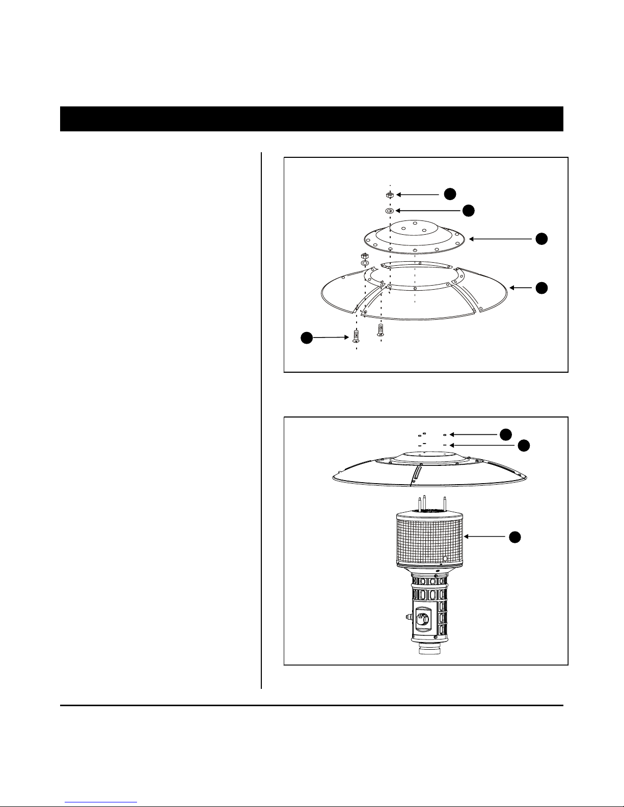
Step 7 ---- Attach Center Reflector to Reflector
Attach center reflectorto the topof reflector (4pcs)
by M6 X10 mm screws(12 pcs) ,
Step 7
1
6mm washers (12pcs) and nuts(12 pcs).
Step 8 ---- Attach Center Reflectorand Reflector
Load center reflectorand reflector tothe top
of head assemblyby
M6 X 70double pointed bolts(3 pcs)
to the topof HeadAssembly
6mm washers (3 pcs) andnuts (3 pcs).
9
NOTE: Assembly of this heater requires
basic mechanical skills. Proper assembly
is the responsibility of the installer.
ASSEMBLY
Step 8
12
13
2
14
12
13
3
10
ASSEMBLY
NOTE: Assembly of this heater requires
basic mechanical skills. Proper assembly
is the responsibility of the installer.
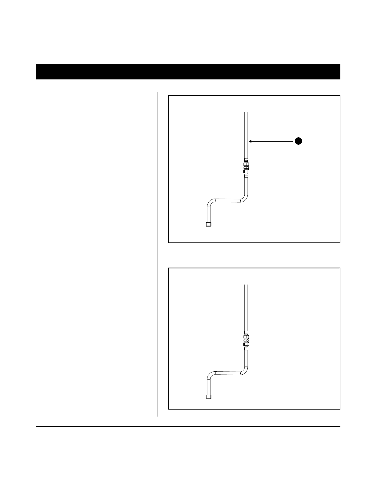
Step 9 ----Connect Gas Hoseto Natural Gas
Step 9
Attach Gas hoseto Natural Gaswith
Quick disconnect device.
Step 10
Step 10 ----Check for leak
YourPatio Heater hasbeen checked atall
factory connections forleaks,Tocheck the
Connection of thegas hose/natural gaspipe.
1)Make leak solutionby mixing 1part liquid
dish soap and3 parts water.
2)Spoon several drops(oruse squirt bottle)
of the solutiononto the gashose/gas pipe
connection.
3)Open the controlpanel access cover.
Squirt all theconnections inside,including
the hose connectioninside the post.
4)Inspect the connectionsand look forbubbles.
5)If no bubblesappear,the connectionis safe.
6)If bubble appear,there is leak,loosenand
re-tighten this connection.
16

11
ASSEMBLY
WARNING:
Step 11
TO BE INSTALLED ONLYBY A
COMPETENT PERSON
Step 11 ---- Disconnect Natural Gas
When Storing or Transporting
1).Turn offthe heater.
2).Turn offthe valve ofnatural gas.
3).Disconnect the gashose.
12
OPERATION
FOR YOUR SAFETY:
If at anytime you areunable to lightburner
and smell gas,wait5 minutes toallow gas
to dissipate beforeattempting to lightheater.
If,after 1 minute,you are unableto light
burner, wait5 minutes andallow flammable
vapors to dissipatebefore attempting to
light heater again.
WARNING
FOR YOUR SAFETY:
Do NOT touch or moveheater for atleast 45
minutes after use.
Allow emitter anddome to coolbefore
touching.
WARNING
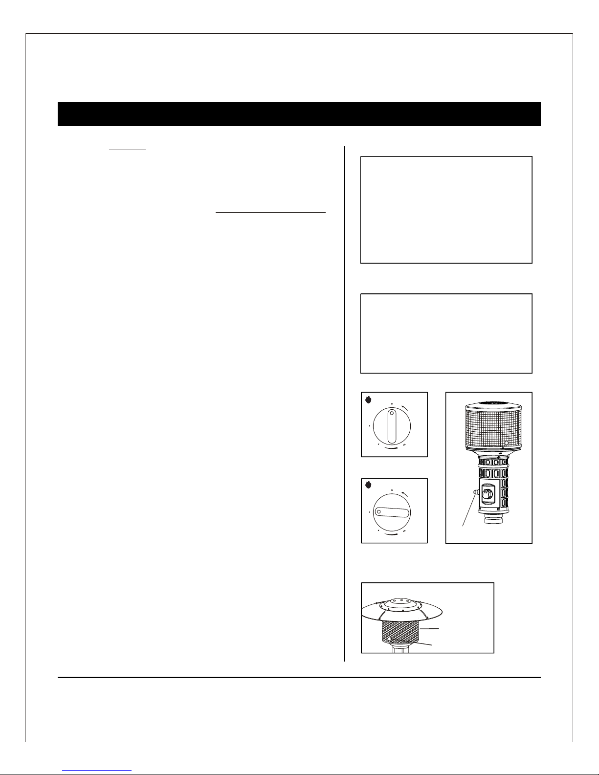
Ignition Hole
Emitter Screen
P
u
s
h
t
o
t
u
r
n
O
F
F
H
G
I
H
L
O
W
T
O
L
I
P
P
u
s
h
t
o
t
u
r
n
O
F
F
H
G
I
H
L
O
W
T
O
L
I
P
Eletronic ignition
WARNING:
DO NOT attempt to operate heater until you have
read and understand all precautions.
Failure to do so can result in serious personal injury, death
or property damage.
Before Turning Gas Supply ON
Yourheater was designedand approved forOUTDOOR USE ONLY. Do NOT
use it insidea building ,orany other enclosedarea.
Make sure surroundingareas are freeof combustible materials,gasoline
and other flammablevapors or liquids.
Ensure that thereis no obstructionto air ventilation.
Be sure allgas connections aretight and thereare no leaks.
Be sure theaccess panel isclear of debris.
Be sure anycomponent removed duringassembly or servicingis replaced
and fastened priorto starting.
Before Lighting
Heater should bethoroughly inspected beforeeach use, andby a qualified
service person atleast annually.
If relighting, alwayswait at least5 minutes.
LIGHTING INSTRUCTIONS
Our heater istested for qualityassurance.
Ignition attempts shouldsucceed 8 outof 10 attempts.
HEATER
HEATER
If you experienceany ignition problem,turn off theheater and gas
supply, and consult "Troubleshooting" on page19.
1)Turn thecontrol knob to "OFF" position.
2)Fully open gasvalve
3) Push incontrol knob andturn counter clockwiseto "PILOT"
position, push inthe ignition buttonand keep thebutton depressing untill
light the pilot.
4) Once thepilot is lit,continue to keepthe control knobdepressed for atleast
30 seconds,After 30 secondsrelease control knob.
5) If pilotdoes not staylit, repeat steps3 and 4.
6) If pilotstill does notstay lit, then:
a) Push ingas control knoband turn counterclockwise to "PILOT"
b) keep depressingthe control knob,put long stemlighter into the
Ignition Hole onthe emitter screento light thepilot.
c) repeat step4.
7) Push inand turn controlknob counter clockwiseto "HIGH" position,
If you wanta lower temperature,push in thecontrol knob andturn
clockwise to the"LOW" position.

OPERATIONOPERATION
CAUTION :
Avoid inhaling fumes emitted from the heater's
first use. Smoke and odor from the burning of oils used in
manufacturing will appear. Both smoke and odor will
dissipate after approximately 30 minutes. The heater
should NOT produce thick black smoke.
NOTE:
""OW
The burner maybe noisy wheninitially turned on.To eliminate excessive
noise from theburner, turnthe Control Knobto the LOW position. Then,
turn the knobto the levelof heat desired.
13
""OW
When heater is ON:
Emitter screen willbecome bright reddue to intenseheat. The color is more
visible at night.Burnerwill display tonguesof blue flame.Theseflames
should not beyellow or producethick black smoke,indicatingan obstruction
of airflow throughthe burners.
RELIGHT
1)Turn thecontrol knob to OFF position.
2)Wait five(5) minutes beforeattempting to relightpilot.
3) Repeat stepsbeginning with step2 of theLighting Instruction above.
SHUT DOWN INSTRUCTIONS
1) Push inand turn controlknob clockwise to"OFF" position.
2) Turnoff the valve of naturalgas.
3)Discomect the gashose.
Note: Afteruse, some discolorationof the emitterscreen is normal.
WARNING :Heater will be hot after use.
Handle with extreme care.
2
1
0
P
u
s
h
t
o
t
u
r
n
O
F
F
H
G
I
H
L
O
W
T
O
L
I
P
P
u
s
h
t
o
t
u
r
n
O
F
F
H
G
I
H
L
O
W
T
O
L
I
P
14
LOCATING HEADER FOR USE
BE CAREFUL: WHEN CERTAIN
MATERIALS OR ITEMS ARE LEFT
UNDER THIS SPACE HEATER WHILE
IN USE, THEY WILL BE SUBJECT TO
RADIANT HEAT AND COULD BE
SERIOUSLY DAMAGED.
This heater is primarily used for the
heating of outdoor patios, decks, spas, pool
and working areas.
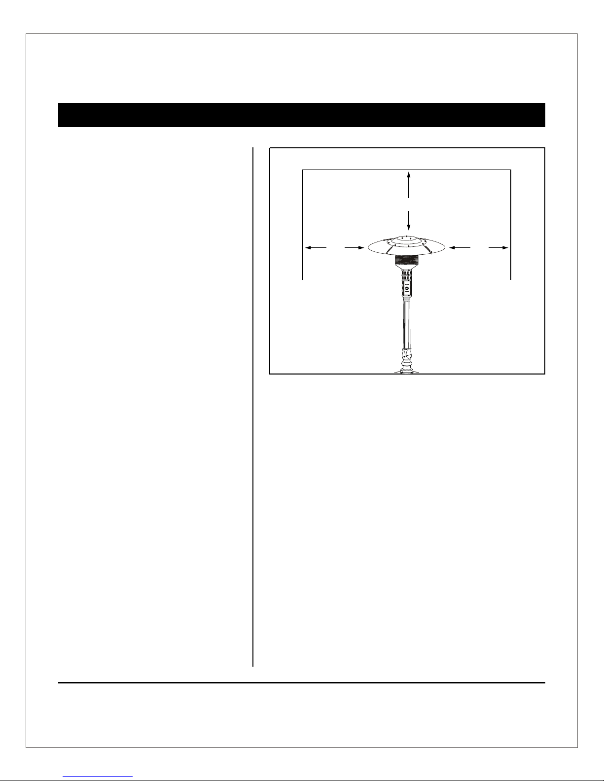
Always make sure that adequate fresh air
ventilation is provided. Follow the spacing
tolerances shown in Figure 1.
This heater clearances, shown in Figure 1,
must be maintained at all times.
This heater must be placed on level, firm
ground.
Never operate in an explosive atmosphere.
Keep away from areas where gasoline or
other flammable liquids or vapors are stored
or used.
Figure 1
24" 24"
36"

15
REPLACING INJECTOR
Step 1
1.Remove the reflectorand emitter byremoving the 4pcs screws( )
that fasten theemitter to thelower screen cone.
2.Remove lower conecylinder by removingthe 4 pcsscrews( )
which attach thelower cone cylinderto the controlcylinder.
3.Remove the 4pcs screws( )at the bottomof control cylinder.
1
1
2
2
3
3
Emitter
Screen
Lower
Cone
Cylinder
Control
Cylinder

16
REPLACING INJECTOR
4
5
4.Use the spannerto take downthe old injector,
assemble the exchangedinjector,and screwit by
spanner.
The picture for pilot flame gas tube exchanged
to 6.4 Aluminum pipe.

17
MAINTENANCE
Toenjoy years ofoutstanding performance fromyour heater makesure
you perform thefollowing maintenance activitieson a regularbasis:
Keep exterior surfacesclean.
Use warm soapywater for cleaning.Never use flammableor
corrosive cleaning agents.
While washing yourunit, be sureto keep thearea around theburner
and pilot assemblydry at alltimes. If thegas control isexposed to
water in anyway, do NOT try to useit. It mustbe replaced.
Air flow mustbe unobstructed. Keepcontrols, burner,and circulating
air passageways clean.Signs of possibleblockage include:
Gas odor withextreme yellow tippingof flame.
Heater does NOTreach the desiredtemperature.
Heater makes poppingnoises.
Heater glow isexcessively uneven.
Spiders and insectscan nest inburner or orifices.This dangerous
condition can damageheater and renderit unsafe foruse. Clean
burner holes byusing a heavy-dutypipe cleaner.Compressed air may
help clear awaysmaller particles.
Carbon deposits maycreate a firehazard. Clean domeand engine with
warm soapy waterif any carbondeposits develop.
WARNING
DO NOT touchor move heaterfor at least
45 minutes afteruse.
Allow all burnerelements to coolbefore
touching.
FOR YOUR SAFETY :
NOTE
In a salt-airenvironment (such asnear an
ocean). corrosion occursmore quickly
than normal. Frequentlycheck for
corroded areas andrepair them promptly.
The installation offixed appliances shallonly be carriedout by competent
persons and bein accordance withthe relevant Codesof Practice.
Warning: This appliance requires a gashose and naturalgas pipe, checkwith
your gas supplierand or productsupplier.
AT LEAST ONCE EACHYEAR check the entirelength of thegas
hose and naturalgas pipe fordamage, if thereis damage, abrasion
or wear, replace the gashose or naturalgas pipe.
Prior to use,check for damagedparts and inspectthe gas hosefrom the
appliance to thegas pipe. Ifthere is damage,abrasion or wear, replace the
hose with partNO 4.
The flame patternat the Emitter Screen should be Visually Checked
whenever heater isoperated.
Check Your Flame:
If flames extendbeyond surface ofthe emitter grid, or thephenomena of
flame lift orlight back, orblack spot isaccumulating on theemitter grid or
reflector, theheater should beTurned OFF immediately.
The heater shouldnot be operatedagain until theunit is serviced
and or repaired.
Normally the burnerflame is blue,but little yellowflame is acceptable.
YellowTip
Primarily Blue Flame
Check Your Hose Assembly:
Maintenance and Cleaning:
AT LEAST ONCE EACHYEAR check the partof the hoseinside the post.
Visually check
Emitter Screen

18
STORAGE
STORAGE :
Between uses:
During periods ofextended inactivity orwhen transporting;
NOTE
Wait until heateris cool beforecovering.
Turn thecontrol knob to"OFF" position.
Turn naturalgas to "OFF"position.
Store heater uprightin an areasheltered from directcontact with
inclement weather (suchas rain, sleet,hail, snow,dust and debris).
If desired, coverheater to protectexterior surfaces andto help prevent
debris in airpassages.
Turn thecontrol knob to"OFF" position.
Disconnect natural gasand move toa secure, well-ventilatedlocation
outdoors. Do NOT store in alocation that willexceed 125 degreesF.
Store heater uprightin an areasheltered from directcontact with
inclement weather (suchas rain, sleet,hail, snow,dust and debris).
If desired, coverheater to protectexterior surfaces andto help prevent
debris in airpassages.

19
TROUBLESHOOTING
PROBLEM PROBABLE CAUSE SOLUTION
Pilot will not light Gas valve may be OFF Turn the gas valve ON
Orifice blocked Clean or replace Orifice
Air in supply system Purge air from lines
Loose connection Check all fittings
Pilot will not stay on Debris around pilot Clean dirty area
Loose connection Tighten connection
Thermocouple bad Replace Thermocouple
Gas leak in line Check connections
Burner will not light Pressure is low
Orifice blocked Remove, clean and replace
Control Valve not ON Turn valve to ON
Thermocouple is bad Replace Thermocouple
Pilot light assembly bent Place pilot in proper
or not in correct location position and retry
Fuel Tank empty Refill LP gas tank
Lack of fuel pressure Fuel tank is near empty
Supply pressure is not enough
Dead battery Replace battery
Table of contents
Other Shinerich Patio Heater manuals

Popular Patio Heater manuals by other brands


Blumfeldt
Blumfeldt Heat Guru 360 manual

Heat Outdoors
Heat Outdoors Athena Plus+ Safety instructions and operation manual

Blumfeldt
Blumfeldt Heat Guard Blackline Assembly instructions

Outsunny
Outsunny 842-274V90 user manual

KALOS
KALOS KLEH133-0300 Assembly instructions

Ravanson
Ravanson OT-1500B Original instructions