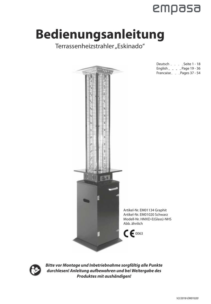
Heat Outdoors Athena Plus+ Operation and maintenance manual

Athena Plus+
Pyramid Flame
Gas Patio Heater
Safety Instructions and Operation Manual
901287P
Heat Outdoors
Unit 9, Stort Valley Industrial Estate
Stansted Road, Bishop’s Stortford
Hertfordshire, United Kingdom
CM23 2TU
www.heat-outdoors.co.uk
01279 466500

2Contents
Contents
Warning . . . . . . . . . . . . . . . . . . . . . 3
Leakage Test . . . . . . . . . . . . . . . . . . . 4
Appliance and Location . . . . . . . . . . . . . . . 4
Safety Precautions . . . . . . . . . . . . . . . . . 5
Installation . . . . . . . . . . . . . . . . . . . . 6
Technical Specications . . . . . . . . . . . . . . 6
Parts List . . . . . . . . . . . . . . . . . . . . . 7
Assembly Instructions . . . . . . . . . . . . . . . 8
Operation . . . . . . . . . . . . . . . . . . . . 12
Customer Service . . . . . . . . . . . . . . . . 15

3
Warning
Warning
Please carefully read all instructions provided before using this appliance. This heater
must be installed in accordance with the instructions and local regulations. The use of
this appliance in enclosed areas can be dangerous and is prohibited.
• Perform the ‘leak test’ after each changing gas cylinder.
Never check for leaks with a naked ame
• Do not store other ammable vapours or liquids near this appliance.
If you smell gas, follow the steps below:
1. Extinguish all naked ames; do not operate any electrical appliances
2. Close the valve of the regulator to stop gas running to the unit and turn the heater to
the OFF position (full disk = • )
3. Ensure the regulator is xed to the bottle correctly.
4. Check the hose from the gas bottle to the unit has no splits - this can be done with
soapy water to identify splits in the hose.
5. If odour persist contact Heat Outdoors or a gas supplier.

4Leakage Test
Leakage Test
Gas connections on the appliance are leak tested prior to shipment. Possible mishandling
of the appliance during shipment can damage the integrity of some parts.
A complete gas leakage test must be performed again at the installation site. Please
follow the procedure below for leakage test.
1. It is advised to make a soap / liquid detergent and water solution to identify any
holes/splits or loose ttings in the tube.
2. Make sure the control tap is in the OFF position (full disk = • ) on the control panel.
3. Apply the solution to the hose using a brush or rag.
4. Turn ON the gas supply and check for bubbles from the hose. If the air bubbles
appear this indicates a leak in the hose.
5. If a leak is present, turn OFF the gas supply immediately, tighten any leaking tting
carefully, turn gas again and recheck.
Appliance and Location
The appliance is for outdoor use only.
Do not use indoors or in an enclosed area.
Always maintain suitable clearance from combustible materials - minimum 800mm from
the top of the unit, and a minimum of 650mm from sides.

5
Safety Precautions
Safety Precautions
• Performance and safety service of this heater should be performed annually by a
qualied gas engineer.
• Do not use the heater in a combustable atmosphere.
• Before using the unit check the hose for splits, twists which may cause gas to leak or
prevent ow.
• Disconnect gas cylinder before moving the heater.
• Do not attempt to modify any parts of the heater.
• The appliance is not recommended to be used in basements, below ground level or
in areas with limited / no ventilation.
• Ensure the heater is placed on a solid and level surface.
• It is recommended that you should change your regulator annually to avoid
blockages.
• Do not clean the heater with cleaners that are combustible or corrosive.
• Do not paint any part of the heater.
• The gas cylinder valve should be turned off when the heater is not in use.
• Avoid using the heater when it is raining to prevent water ingress.
• Keep children and vulnerable people away from the heater when in use.
• Do not move the heater when it is in use.
• Check the heater immediately if any of the following exists:
- There is smell of gas.
- The heater performance of the heater seems to be reduced.
- The burner makes popping noise during use (a slight popping noise is normal
when the ame is extinguished after use).
• When the heater is in use the surface of the grills, reector and glass will reach a
high temperature. Do not touch these parts.
• Do not obstruct the ventilation holes of the cylinder housing.
• It is recommended that the gas tube is replaced annually to avoid any splits or holes
forming.
• Only use the gas specied - 13kg-15kg Propane patio gas.
• In adverse weather conditions it is advised the heater is stored undercover or inside
where possible.

6Installation
Installation
Important safety requirements:
THIS APPLIANCE IS FOR OUTDOOR USE ONLY
1. It is not recommended for this heater to be installed or used indoors, garages or any
other enclosed area.
2. DO NOT place articles on or against this appliance.
3. DO NOT use or store ammable materials near this appliance.
4. DO NOT operate this appliance unless it is fully assembled with re ector and
protection guard in place.
5. Installation and repair should be done by a quali ed service person. The appliance
must be inspected before use and at least annually serviced by a quali ed gas
engineer. More frequent cleaning may be required.
Technical Specifi cations
Item Number KLD7001S
KLD7001SS
901287P
Flame Heater
0359CR1461
Nominal HEAT
INPUT
10.5 kW (762 g/h)
Appliance
Category
I3+(28-30/37) I3B/P(30) I3B/P(37) I3B/P(50)
Gas Reference G30/G31 G30/G31 G30/G31 G30/G31
Normal Gas
Pressure
28-30/37 mbar 30 mbar 37 mbar 50 mbar
FOR USE OUTDOORS ONLY
Close the valve of the gas cyclinder or the regulator after use.
The use of this applicance in closed areas can be dangerous and is PROHIBITED.
Read the instructions before using this appliance.
The appliance must be installed in accordance with the intructions and local regulations.
Country of destination:
I3+(28-30/37) for BE-CH-CY-CZ-ES-FR-GB-GR-IE-IT-LT-L-U-LV-PT-SK-SI
I3B/P(30) for BE-CY-DK-EE-FI-FR-HU-IT-LT-NL-NO-SE-SI-SK-SK-RO-HR-TR-BG-
I3B/P(37) for PL
I3B/P(50) for AT-CH-DE-SK

7
Parts List
Parts List
Part Number Part Name Picture Quantity Remarks
1 Bottom Plate 1
2 Control Box 1
3 Middle Plate 1
4 Damper 1
5 Upper Support 4
6 Lower Support 4
7Glass Tube 1
8Reector 1
9 Lower Protection
Guard
4
10 Wheels 1
11 Fixing Bracket 4
12 Side Panel 3
13 Front Panel 1
14 Handle 1
15 Chain 1
16 AA Battery 1
17 Rubber Ring 1
18 Screw 3/16” 66

8Assembly Instructions
1. Attach wheels (10) to bottom plate (1). 2. Connect and x 4 x lower support (6) to the
bottom plate (1) and middle plate (3) with
screws (19).
Assembly Instructions
18
3. Connect 4 upper supports (5) to the lower
supports (6) with screw (18), then x the
upper plate (4) with screws (18).

9
Parts List
4. Unscrew the red ignitor button on the
control box and insert the AA battery (16)
with the POSITIVE end facing outwards.
Then attach the control box (2) underneath
the middle plate (3) with screws (18).
5. Carefully put the glass tube (7) up through
the center of the hole in the upper plate (4).
Make sure the rubber ring (17) is attached
on the lower end of the glass tube. Now
place the glass tube through the hole on
the middle plate (3). Check to ensure the
glass tube covers the center hole of the
middle plate.
18
16
15
17
6. Attach the reector (8) onto the upper plate
(4) and x with screws (18).

10 Parts List
7. Attach the protection guards (9) to the
upper frame by inserting the hooks at the
top of the guards into the holes on the
supports. Repeat at the bottom of the
supports. Secure the protection guards
to the top of the supports with the xing
brackets (11) and screw in place.
8. Fix the sides panels (12) with the screws
(18). Note: Do not cover the side where the
control knob is.
19
11
13
14
9. Screw the handle (14) on the
front panel (13) - attach the
panel by inserting its two hooks
into the holes on the bottom
plate. Hook the chain (15) to
the hole in the control box,then
close the panel to the middle
plate - the panel is attached
by the magnets. Tips: the
chain can hole the panel while
operating the control.

11
Parts List
10. Connect gas hose to 20. Ib. LPG cylinder
(not included). Attach regulator to cylinder.
Tighten securely. Move cylinder to the
plate of base assembly. Attach the cylinder
to the base with 3pcs M8x12 bolts and
tighten it in order to prevent the cylinder
from moving on the base. Note: The
regulator with gas hose is supplied.
Complete

12 Operation
Operation
Preparation
You will need to purchase a suitable size LPG cylinder that can be installed to the
compartment. You must use a pressure regulator and exible tube which complies with
the outlet pressure of the appliance. Connect the hose to the hose connector on the
control box.
Warning
Always test the hose for leaks during the leakage test desribed at the start of the
instruction manual.
• Never use the heater while it is raining, the glass tube may break if suddenly coming
into contact with water.
• Never splash liquid on the glass tube when the heater is on.
• The glass tube will be extremely hot when in operation, never try to touch it.
• Children and vulnerable people must be kept away from the heater at all times.
• Always ensure the heater stands rmly, the glass tube may break if the heater falls.
• Never use the heater if the glass tube has signs of damage ie. cracking.

13
Operation
Ignition Instructions
Check and ensure that an AA battery is inside the
ignition chamber and has power. Ensure the anode (+)
faces outwards.
1. Ensure that the control knob is OFF. Slowly open
the gas cylinder valve.
2. Press and turn the control knob to LIGHT position,
push the igniter to generate spark while keeping
control knob in pressed position
3. Check for pilot ame through glass tube. If pilot does not light, turn control knob
to OFF position wait two minutes minimum and try again from the start. Several
attempts may be necessary.
4. If the pilot s lit, keep control knob pressed for 15 seconds then turn the control knob
to LOW.
5. For maximum heat turn control knob to HIGH.
6. To turn heater off, turn control knob to OFF.
7. Close the valve of the gas cylinder or the regulator after use.
OFF
LIGHT
LOW
HIGH

14 Operation
Cleaning & maintenance
To enjoy outstanding performance of your heater for years make sure you perform the
following maintenance activities on a regular basis:
• Keep exterior surfaces clean.
• Use warm soapy water for cleaning. Never use ammable, corrosive or abrasive
cleaners.
• While washing your unit, be sure to keep the area around the burner and pilot
assembly dry at all time. If the gas control is exposed to water in any way, do NOT try
to use it. It must be replaced.
• After a long break from operation, the unit should be inspected for spiders, spider
webs or other insects.
• Air ow must be unobstructed. Keep controls. Burner and circulating air
passageways clean.
Signs of possible blockage include:
• Gas odour with extreme yellow tipping of ame.
• Heater does NOT reach the desired temperature.
• Heater glow is excessively uneven.
• Heater makes popping noises.
• Spider and insects can nest in burner or orices. This dangerous condition can
damage the heater and render it unsafe for use. Clean burner holes by using a heavy-
duty pipe cleaner. Compressed air may help clear away smaller particles.
• Carbon deposits may create a re hazard. Clean reector and glass tube inside with
soapy water if any carbon deposits develop. Always be careful when cleaning the
glass tube.
Storage
Between uses:
• Turn the control knob to “OFF” position.
• Turn LPG cylinder to “OFF” position.
• Store heater upright in an area sheltered away from weather conditions (such as rain,
sleet, hail, snow).
• If desired, cover heater to protect exterior surfaces and to help prevent dust and
debris collecting in air passages.

15
Customer Service
During periods of extended inactivity or
when transporting:
• Turn the control knob to “OFF” position.
• Disconnect LPG Cylinder and move to a secure, well-ventilated location outdoors.
• DO NOT store in a location that will exceed 50 degrees C.
• Store heater upright in an area sheltered away from weather conditions (such as rain,
sleet, hail, snow).
• If desired, cover heater to protect exterior surfaces and to help prevent dust and
debris collecting in air passages.
Disposal
In accordance with European Directive 2001/96/EG concerning used
electrical and electronic appliances (waste electrical and electronic
equipment – WEEE), please return any electrical equipment that you will no
longer use to the collection points provided for their disposal.
This symbol indicates that the appliance cannot be treated as normal
domestic trash, but must be handed to a collection point for recycling electric
and electronic appliances.
Information concerning where the equipment can be disposed of can be obtained from
your local authority.
Customer Service
• Repairs must be carried out by authorized specialists, thus ensuring electrical safety.
• Please contact with the service agent or a suitably quali ed electrician.
• Improper repairs could lead to danger to the user.
Warranty does not cover damage of failure which results from alteration, accident,
misuse, abuse, neglect, commercial use or improper maintenance. In line with our policy
of continuous product development we reserve the right to change the product and
documentation speci cations without notice.
Warning
FOR YOUR SAFETY:
• DO NOT touch or move heater for at least
45 minutes after use.
• Allow all burner elements to cool before
Touching.
NOTE
• In a salt-air environment (such as near an
Ocean) corrosion occurs more quickly
than normal.
• Wait until heater is cool before covering.

Heat Outdoors
Unit 9, Stort Valley Industrial Estate
Stansted Road, Bishop’s Stortford
Hertforshire, United Kingdom
CM23 2TU
www.heat-outdoors.co.uk
01279 466500
Table of contents
Other Heat Outdoors Patio Heater manuals

Heat Outdoors
Heat Outdoors 902114 Operation and maintenance manual

Heat Outdoors
Heat Outdoors UMBRA Tulip Operation and maintenance manual

Heat Outdoors
Heat Outdoors Shadow Diffusion Operation and maintenance manual

Heat Outdoors
Heat Outdoors SHADOWFB2400 Operation and maintenance manual

Heat Outdoors
Heat Outdoors Goliath User manual

Heat Outdoors
Heat Outdoors Shadow Nirvana Instruction Manual

Heat Outdoors
Heat Outdoors CH18A11W2 901698 Operation and maintenance manual

Heat Outdoors
Heat Outdoors 902112 Operation and maintenance manual

Heat Outdoors
Heat Outdoors LONDON User manual

Heat Outdoors
Heat Outdoors 901735 Operation and maintenance manual