2. SPECIFICATIONS WK
-2-
2.1 STANDARD SPECIFICATIONS
Current Output
4 to 20mA
OUTPUT RANGE
0 to 100µm pk-pk
0 to 125µm pk-pk
0 to 200µm pk-pk
0 to 250µm pk-pk
0 to 400µm pk-pk
4 to 20mA OUTPUT
CONVERSION
ACCURACY
±1.5 % of Full Scale Range
(From test signal input pin to current output)
MAX. LOAD
REGISTANCE
43.5 × (Vps-12) ( (Vps=Power supply voltage)
NOT-OK FUNCTION Current output : 3.6mA or less.
Not-OK condition : Open or short of sensor,
Outside of linear range.
Delay time to resume ; 2 to 3 seconds after
Not-OK condition is removed.
GAP Output
(Wave form output)
CALIBRATION
MATERIAL
JIS SCM440 FLAT (AISI 4140 equivalent )
LINEAR RANGE* 1.4mm (Gap : 0.3 to 1.7mm)
SCALE FACTOR* 7.87mV/µm
SCALE FACTOR
ERROR*
7.87mV/µm±6.5% typ.
(including interchangeability errors)
Step : 200µm, Target : 30 mm dia.
OUTPUT
IMPEDANCE*
10kΩ(It is calibrated load impedance at 10MΩ)
System
1. CALIBRATION MATERIAL
MODEL WK-142K 2-wire Vibration Transmitters are calibrated with
JIS SCM440 (AISI 4140 equivalent) flat surface (more than 15 mm
dia.).
It is not calibrated with any other target.
2. CONNECTOR ISOLATION, etc.
The connector connecting the sensor cable and the extension cable
shall be insulated with the attached insulation sleeve (transparent
shrink tube) or fluoro resin insulation tape.
The vinyl-insulating tape shall not be used, which may cause the
wiring trouble in the case of the temperature more than 80°C.
The connector shall not be located in the oil environment.
The oil penetration to cable through the connector may cause the
sensitivity change, due to the change of the cable capacitance.
3. MEGGER TEST OF SIGNAL CABLE
If megger test is made on the signal cable (2-wire shielded cable), be
sure to discharge the charged electric load before connecting the
cable to transmitter.
If this caution is not adhered the transmitter could be damaged.
4. WIRING BETWEEN GAP OUT TERMINAL AND EQUIPMENT
a). Non-grounding type equipment
Connect directly with coaxial cable within 3 meters long.
b). Grounding type equipment
Use an isolator between the transmitter and the equipment.
Use coaxial cable within 3 meters long between the transmitter
and the isolator.
5. SENSOR INSTALLATION
Not available for rainwater at out door use.
It may cause the sensitivity change and insulation down.
FREQUENCY
RESPONSE*
5Hz to 6,000Hz (+0dB, -3dB) at 900µm Gap
TEMPERATURE
RANGE OF
TRANSMITTER
Operating : 0 to 70°C(32 to 158°F)
Storage : -34 to +100°C(-29 to +212°F)
TEMPERATURE
RANGE OF SENSOR
AND EXTENSION
CABLE
Operating : -34 to +177°C (-29 to +350°F)
(Connector : Max. 125°C (257°F))
Storage : -34 to +177°C (-29 to +350°F)
(Connector : Max. 125°C (257°F))
RANGE OF
TEMPERATURE AT
EXPLOSION PROOF
CONSTRUCTION
CSA,ATEX :
0 to +70°C (Sensor, Ext. Cable &Transmitter)
RELATIVE HUMIDITY
95%RH (non condensing)
POWER SUPPLY
VOLTAGE
12 to 35VDC
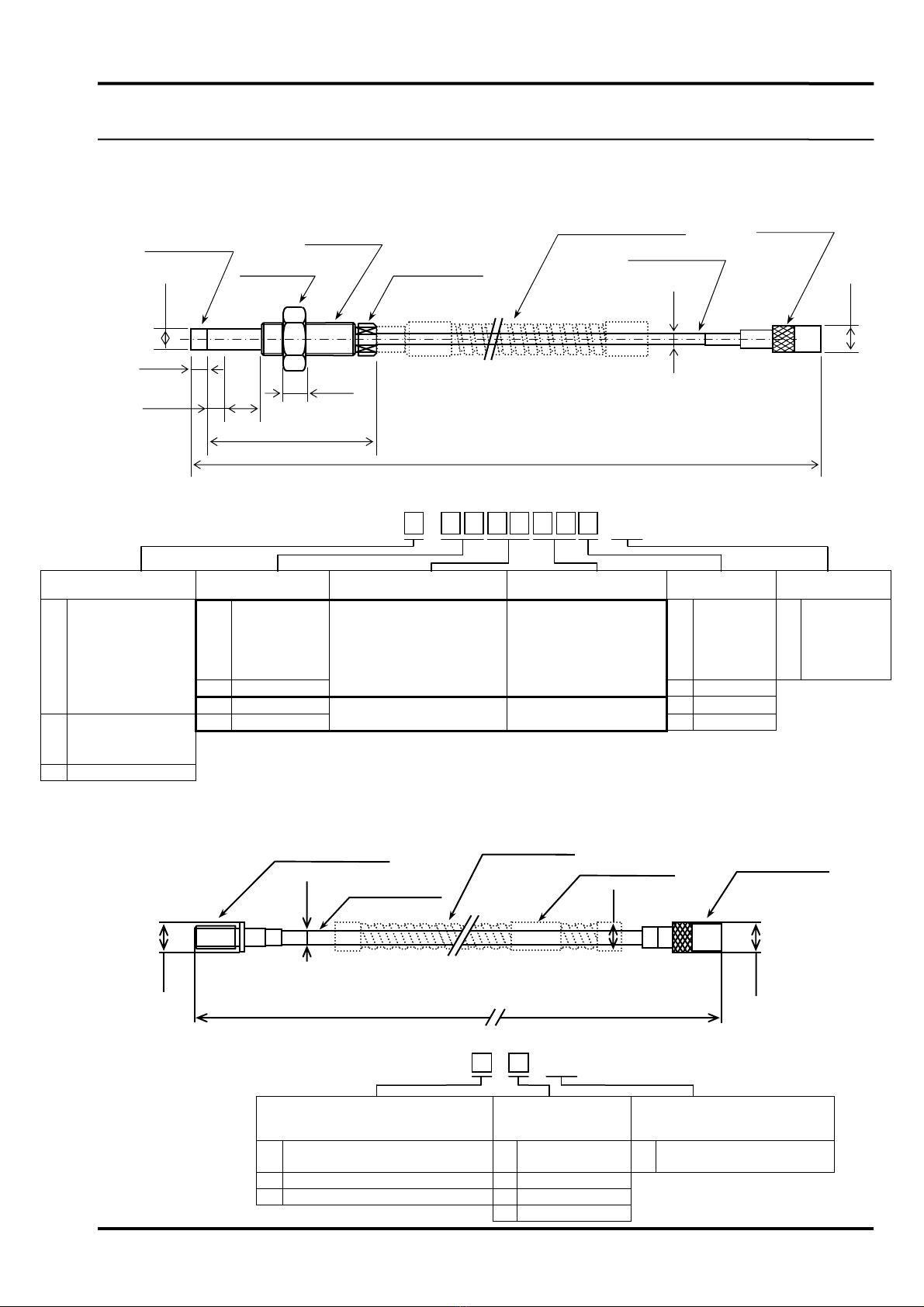
SENSOR TIP
DIAMETER
Approx. 5.5mm (0.217 inch) dia.
CABLE DIAMETER Approx. 2.7mm (0.106 inch) dia.
CONNECTOR
DIAMETER
Approx. 7.1mm (0.280 inch) dia.
SYSTEM CABLE
LENGTH
5m or 7m
TRANSMITTER SIZE (L) 100mm × (W) 74 mm × (H) 50 mm
(3.94 in) (2.91 in) (1.97 in)
Mass : Approx. 530g (1.2 lb)
*The above specifications apply at 25°C with 24VDC power supply and
SCM440 (AISI 4140 equivalent) steel flat target.
Other
SPECIFICATIONS NOTICE
CONFIGURATION
WL Sensor WW Extension Cable
WK Transmitter
Connecto
System Cable Length : 5m or 7m
30101E1.9