Shinko Denshi FZ623Ex User manual

410026M31
Intrinsically
Safe
Explosion
-
Proo
f
High-Precision Tuning Fork Scale
FZ-Ex Series
Operation Manual
SHINKO DENSHI CO., LTD.
IMPORTANT
•
To ensure safe and proper use of the balance, please read this
manual carefully.
•
After reading this manual, store it in a safe place near the balance, so
you can review it as needed.


-i-
Preface
Thank you very much for having purchased our dust- and water-proof intrinsic safety
explosion-proof structure electronic scale.
This document is the Operation Manual for the following dust- and water-proof intrinsic safety
explosion-proof structure electronic scale.
In the first place, install this product properly referring to the Installation Manual attached
separately, and then read this document.

-ii-
Instructions
●
The copyright of this document belongs to SHINKO DENSHI CO., LTD. Reprinting or
duplicating of all or part of this document without notice shall not be allowed.
●
Please note that product improvement or modification may cause partial discrepancy
between the product and the description of this document.
●
The description of this document is subject to change without notice.
●
This document has been created carefully. If, however, any error or imperfection is found
by any chance, please let us know.
●
Documents of which pages are missing or irregularly bound will be exchanged. Please
inform the store where you purchased the product or our sales department.
●
Trouble related to the product or system will be dealt with in accordance with the
individual maintenance contract. Please note, however, that we will not take
responsibility for consequential trouble such as discontinuation of operation caused by
the product trouble.
●
is the registered trademark of SHINKO DENSHI CO., LTD. Company names
and product names appearing in this document are the trademarks or registered
trademarks of the respective company concerned.

-iii-
Important Notice
・It should be known that this product contains potential danger. And so
please be sure to observe this document when installing, operating or
servicing this product.
・SHINKO DENSHI CO., LTD. will not take any responsibility for any
injury or damage caused by the non-observance of this document or
misuse or unauthorized modification of this product.
●
Potential dangers are increasing in the industrial equipment industries due to the
advent of new materials and processing methods, and speeding up of machines. It
is impossible to foresee all situations related to these dangers. In addition, there
are so many “impossible” and “don’ts” and so writing all of them in the operation
manual is impossible. Therefore, it is safe to think that what is not written in the
operation manual “cannot be performed” unless the operation manual positively
writes “it is possible.” When performing installation, operation, maintenance or
inspection of this product, not only observe what is written or indicated in this
document or on the product surface but also pay adequate consideration to safety
measures.
●
The copyright of this document is held and reserved by SHINKO DENSHI CO.,
LTD. Duplicating or disclosing its drawings and engineering materials without prior
approval of SHINKO DENSHI CO., LTD. in writing is not permitted.
●
For any question or further information concerning this document, please contact
the store where you purchased the product or with its model (type) name and serial
number informed.
●
Manufacturer: SHINKO DENSHI CO., LTD.
Adress: 3-9-11 Yushima, Bunkyo-ku, Tokyo 113-0034 JAPAN

-iv-
How to use this document
■Symbols used in this document
Understand the meaning of the following symbols and observe the instructions of this document.
Symbols
Meaning
Used for the situation that invites an imminent risk of death or severe injury
unless avoided.
Used for the situation that invites a risk of death or serious injury unless
avoided.
Used for the situation that damages device/equipment, or destructs, deletes or
overtypes data unless avoided.
Used for the situation in which special care should be taken or specific
information is emphasized
Used for reference information on operation
Used for “Prohibition” items
Used for “Mandatory” items requiring positive action
Used for prohibition items to avoid “Electrical shock”.
This symbol indicates a legal metrology.

-v-
■About how to read this document
This document consists of the following contents:
■Symbols used in this document
Understand the meaning of the following symbols and observe the instructions of this document.
This product
/The product
Refers to the product.
[On/Off] key
The name of an operation key located in front of the main unit is
represented in a bracket ([ ]).
“Mode”
A message on the display is represented in double quotation marks
(“ ”).
Push the key
Signifies pushing lightly an operation key once.
Push the key long
Signifies keeping pushing an operation key until the designated
indication appears.
1 When beginning to use
Describes about operating precautions, names
and functions of each section, etc. Please be
sure to read this section when using this product
for the first time.
2 Basic usage
Describes about basic usage related to weighing
such as how to turn on and off the power in
addition to the setting procedures to set various
functions.
3 Functions related to the operation
Describes about setting items to change the
operation of the scale.
4 Functions related to the performance
Describes about setting items related to the
indication stability and the response speed of the
scale.
5 User information setting
Describes about setting items related to the
various user’s IDs, and their upper and lower
limits.
6 External input/output functions
Describes about setting items related to the
specifications and conditions in regard to the
external communication.
7 Functions related to the lock
Describes about setting items related to change
prohibitions and invalid keystrokes on each menu
item.
8 Controlling and adjustment functions
Describes about setting items related to the scale
ID setting, the span adjustment and the date and
time setting.
9 Execution menu
Describes about menus other than setting
menus.
10 When this is the case
Describes about methods of troubleshooting this
product such as how to respond to errors and
when you are in need of help.
Appendix
Provides necessary data such as the
specifications of this product.

-vi-
Contents
Preface.................................................................................................................................. i
Important Notice...................................................................................................................iii
How to use this document....................................................................................................iv
Contents...............................................................................................................................vi
1Prior to use .....................................................................................................................1
1-1 Precautions ....................................................................................................................1
1-2 Names and functions of each section.............................................................................3
1-3 Performance of operation keys.......................................................................................4
1-4 How to interpret the display............................................................................................5
1-4-1 Main LCD........................................................................................................................5
1-4-2 Sub LCDs ( i03 only).......................................................................................................6
1-4-3 LCD character font..........................................................................................................6
2Basic usage....................................................................................................................7
2-1 Turning on / off the power, and checking for the operation.............................................7
2-2 Making a zero adjustment ..............................................................................................8
2-2-1 Zero adjustment range when in use................................................................................9
2-3 Weighing an object placed on a container (tare) ..........................................................10
2-4 Weighing with an object to be weighed added ............................................................. 11
2-5 Selecting the main LCD indication................................................................................12
2-6 Selecting the sub LCD indication ( i03 only).................................................................12
2-7 Basic operation.............................................................................................................13
2-7-1 Hierarchy of a setting menu..........................................................................................13
2-7-2 Operation of the setting menu, setting of various functions ..........................................14
2-7-3 Operation of the setting menu, inputting of numeric values..........................................16
2-7-4 Operation of the setting menu, inputting of characters .................................................17
3Functions related to the operation................................................................................19
3-1 Hierarchy of functions related to the operation.............................................................19
3-2 Unit setting ...................................................................................................................20
3-3 Percent scale function..................................................................................................20
3-4 Adding function.............................................................................................................21
3-4-1 Weighing by means of the plus side addition................................................................22
3-4-2 Weighing by means of the minus side addition.............................................................23
3-5 Comparator function.....................................................................................................24
3-5-1 How to perform discrimination ......................................................................................24
3-5-2 Discrimination criteria, and upper and lower limits setting ............................................24
3-5-3 Comparator function setting..........................................................................................25
3-6 Buzzer setting...............................................................................................................26
3-7 Bar graph indication .....................................................................................................26
3-8 Conditions for stability waiting......................................................................................27
3-9 Tare weight value storage function...............................................................................27
3-10 Direct start....................................................................................................................28
3-11 Auto power-off..............................................................................................................28
4Function srelated to the performance...........................................................................29
4-1 Hierarchy of functions related to the performance........................................................29
4-2 Zero tracking ................................................................................................................30

-vii-
4-3 Stability discrimination width.........................................................................................30
4-4 Stability discrimination frequency .................................................................................31
4-5 Response speed ..........................................................................................................31
4-6 Weight renewal interval................................................................................................32
5User information setting................................................................................................33
5-1 Hierarchy of user information setting............................................................................33
5-2 Measurer’s ID setting ...................................................................................................33
5-3 Product name ID setting...............................................................................................34
5-4 Lot number setting........................................................................................................34
5-5 Code number setting....................................................................................................34
5-6 Preset tare weight setting.............................................................................................35
5-6-1 Inputting of a preset tare weight value..........................................................................35
5-6-2 Registration of a preset tare weight value.....................................................................37
5-6-3 Calling of a preset tare weight value.............................................................................37
5-7 Setting of a percent scale reference value ...................................................................38
5-8 Setting of the discrimination value of the comparator function .....................................39
5-8-1 Numeric value setting method ......................................................................................39
5-8-2 Actual value setting method..........................................................................................42
5-9 Coefficient value setting ...............................................................................................45
6External input/output functions.....................................................................................46
6-1 Hierarchy of the external input/output functions ...........................................................46
6-2 Connecter terminal numbers and their functions..........................................................47
6-3 FZ communication format (CRC provided)...................................................................47
6-4 GZIII format..................................................................................................................47
6-4-1 Basic communication specification ...............................................................................47
6-4-2 Basic data output format...............................................................................................48
6-4-3 Meaning of the data......................................................................................................48
6-4-4 Input command composition.........................................................................................49
6-4-5 Transmission procedure ...............................................................................................49
6-4-6 Command format..........................................................................................................50
6-5 GZII format...................................................................................................................51
6-5-1 Command format..........................................................................................................51
6-6 Response.....................................................................................................................52
6-6-1 Response command format (when set to the A00, Exx format)....................................52
6-6-2 Response command.....................................................................................................52
6-6-3 Response command format (when set to the ACK, NAK format)..................................52
6-6-4 Response command.....................................................................................................52
6-7 External contact input (tare weight subtraction / zero adjustment / tare weight subtraction &
zero adjustment) ..........................................................................................................................52
6-8 Power supply box communication setting ....................................................................53
6-9 Maintenance setting .....................................................................................................55
7Functions related to the lock.........................................................................................56
7-1 Hierarchy of functions related to the lock......................................................................56
7-2 Locking of functions related to the operation................................................................56
7-3 Key lock function..........................................................................................................57
7-4 Total lock release..........................................................................................................57
8Controlling and adjustment functions ...........................................................................58
8-1 Hierarchy of controlling and adjustment functions........................................................58
8-2 Outputting of the span adjustment result......................................................................59

-viii-
8-3 Span adjustment history...............................................................................................59
8-4 Scale ID setting............................................................................................................60
8-5 Maintenance setting .....................................................................................................60
8-6 Date and time setting ...................................................................................................61
8-7 Date indication format ..................................................................................................61
8-8 Output character setting...............................................................................................61
8-9 Password control..........................................................................................................62
8-10 Password change.........................................................................................................62
8-11 Password cancellation history......................................................................................63
8-12 Operation of minimum weight indication ......................................................................64
8-13 Minimum weight indication value setting......................................................................64
8-14 Designation of minimum indication...............................................................................65
8-15 Reset to the factory settings.........................................................................................67
8-16 Span adjustment ..........................................................................................................67
8-17 Setting for maintenance ...............................................................................................70
9Execution menu............................................................................................................71
9-1 Operation of the execution menu .................................................................................71
9-2 Calling of the registered user information.....................................................................72
9-3 Registration of user information....................................................................................73
9-4 Calling of device setting information.............................................................................74
9-5 Storage of device setting information ...........................................................................74
9-6 Printing of the GLP header...........................................................................................75
9-7 Printing of the GLP footer.............................................................................................75
9-8 Program number and check sum indication .................................................................76
9-9 Outputting of weight data..............................................................................................77
9-9-1 Outputting of tare weight...............................................................................................77
9-9-2 Outputting of gross weight............................................................................................77
9-9-3 Outputting of accumulated value. .................................................................................78
9-10 Indication of minimum weighed value ..........................................................................78
10 Troubleshooting..........................................................................................................79
10-1 Error messages..........................................................................................................79
10-2 Troubleshooting..........................................................................................................82
10-3 Maintenance method..................................................................................................82
Appendix ............................................................................................................................83
Appendix 1 Specification ....................................................................................................83
Appendix 1-1 Connectable scales..........................................................................................83
Appendix 1-2 Functional specification....................................................................................84
Appendix 1-3 Dimensional outline drawing............................................................................85
Appendix 2 Operation of the setting menu .........................................................................86
Appendix 3 Setting menu hierarchy list ..............................................................................88
Appendix 4 Print sample.....................................................................................................93
Index of Terms....................................................................................................................95

FZ- Ex series operetion manual 1Prior to use
-1-
1Prior to use
1-1 Precautions
■ No disassembling or modification.
Unless specifically stated in this document, disassembling or modification of this product,
mounting or removal of an undesignated component no longer maintains the function of the
explosion-proof structure, leading to a serious accident or bodily injury.
■ Install the power supply box in“non dangerous location.”
Use of the power supply box in a dangerous place will cause trouble such as an explosion or
a fire.
■ Connect the grounding terminal and cables properly.
Improper connection of the grounding terminal and cables will cause trouble such as an
explosion or a fire.
■ Do not replace fuse, optional slots of the power supply box or access to the
AC power terminal when the AC power cord is connected to the mains power.
That may cause an electric shock, short-circuiting or failure. Make sure disconnect from the
AC mains or shut down theAC mains before accessing to those parts.
■ Do not connect the cables with its connector or jack being wet.
That may cause an electric shock, short-circuiting or failure.
■ Do not wet the power supply box.
That may cause an electric shock, short-circuiting or failure.
■ Do not open the AC connector cover unless the power supply box is
installed as a built-in unit on a distribution board or other enclosure of which
access is permitted to the trained and authorised persons only.
That may cause an electric shock, short-circuiting or failure.
■ Do not move the device with a sample to be weighed set on the scale.
That may cause the sample to fall from the weighing pan, leading to a bodily injury or
destruction of the sample.
■ Do not connect to the main unit the power supply cord, scale cable, or
communication cable with its connector or jack being wet.
That may cause an electric shock, short-circuiting or failure.
■ Do not use the product on an unstable table or a place that is subject to
vibration.
That may cause the article to fall from the weighing pan, leading to a bodily injury or
destruction of the article. Besides inaccurate weighing may result.
■ Do not move the scale holding its windshield.
That may cause the scale itself to fall, leading to a bodily injury or malfunction of the scale
itself. Be sure to hold the main unit of the scale to move it.
■ Do not place an unstable sample on the weighing pan.
The sample may fall down and cauyse injury. Put an unstable sample in a container (tare)
before weighing it.

1Prior to use FZ-Ex series operetion manual
-2-
■ Do not use the product in an abnormal condition.
If it should happen that an abnormal event such as smoking or unusual odor occurs, ask the
store where you purchased the product for repair. Keeping using the product may result in an
electric shock or fire. In addition, do not ever try to repair it for yourself, or very dangerous
situation is likely to occur.
■ Do not touch the electrode with a wet or dirty hand.
Otherwise, an electric shock or short-circuiting may result.
■Avoid miswiring of the barrier.
Erroneous barrier wiring in the power supply box is likely to cause failure.
■Do not give a shock to the scale.
It may cause breakage or failure. Place a sample to be weighed softly.
■Do not let an overload situation (o-Err indication) continue.
It may cause breakage or failure. Remove the sample to be weighed immediately.
■Do not use volatile solvent.
Use of volatile solvent is likely to deform the main unit. Dirt on the main unit should be
removed with a piece of dry cloth or cloth wet with small amount of neutral detergent.
■Do not use the product where wind from an HVAC equipment directly
applies.
Accurate weighing may be impeded due to the fluctuation of surrounding temperature.
■Do not use the product where there is direct sun.
Accurate weighing may be impeded due to the rise of internal temperature.
■Do not use the product where floor is soft.
Accurate weighing may be impeded due to the tilting of the main unit when an object is
placed on it.
■Do not use the product where there is violent fluctuation of surrounding
temperature or humidity.
Accurate weighing may possibly be impeded. Use within a temperature range of 5 to 40 C
and below a humidity of 85% RH.
■Do not use the product on an unstable table or a place that is subject to
vibration.
It may cause not only inaccurate weighing but also the sample to fall from the weighing pan,
leading to a bodily injury.
■Be sure to make adjustment at the time of installation or changing a use
place.
There occurs an error in measurement value. For the sake of accurate measurement, be
sure to make adjustment.
■Check for an error periodically.
Use environment and chronological change cause an error in measured value, leading to an
inaccurate measurement.
■Align the level of the scale without fail before use.
Weighing with a slanted scale causes an error, leading to an inaccurate measurement. Put
the scale on a robust place.
FZ- Ex series operetion manual 1Prior to use
-3-
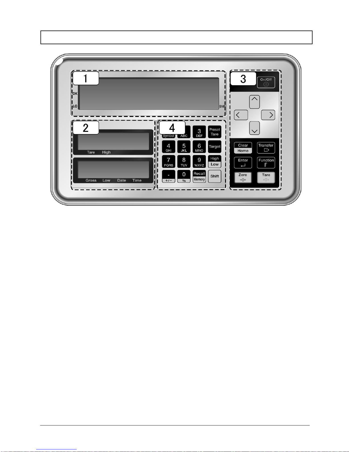
1-2 Names and functions of each section
1
Main LCD
3
Main keys
2
Sub LCDs ( i03 only)
4
Numeric keypad

1Prior to use FZ-Ex series operetion manual
-4-
1-3 Performance of operation keys
No.
Type / name of a key
Performance
1
[On / Off]
Turns on and off the power for the scale.
2
[Direction]
Used for function setting.
3
[Transfer]
Used for outputting.
4
[Function F]
Used for function calling.
5
[Tare]
Used for tare weight subtraction.
6
[Clear Home]
Used for cancelling the setting.
7
[Enter]
Used for finalizing various setting values.
8
[Zero]
Used for zero adjustment.
9
[Preset tare]
Used for setting preset tare weight value.
10
[Target]
Used for setting the reference value for comparator function.
11
[High / Low]
Used for setting the upper and lower limit values for comparator
function.
12
[Shift]
Used for inputting the key function indicated in red.
13
[Recall / Memory]
Used for registering or calling the preset tare weight value or
user information.
14
[Numeric keypad]
Used for inputting a numeric value or setting an ID.

FZ- Ex series operetion manual 1Prior to use
-5-
1-4 How to interpret the display
1-4-1 Main LCD
No.
Symbol
Name
Description
1
Gram
Represents gram unit.
2
Kilogram
Represents kilogram unit.
3
Percent
Lights when in the percent scale mode.
4
Zero point
Indicates the zero point.
5
Plus
Plus
6
Minus
Minus
7
Lower right
Shift
Represents that the [Shift] key was pushed.
8
Tare weight subtraction
Indicates that the tare weight is being subtracted.
9
Preset tare weight
Indicates the preset tare weight.
10
Stable indication
When illuminated: The scale is in the stable condition.
When not illuminated: The scale is not in the stable
condition.
11
Addition available
- Lights in the standby status.
- Addition available status when the adding function is used.
12
Memory access
- Flashes when the scale is in the process of stabilization.
- Lights when writing in the memory.
13
Accumulated values
Lights when various accumulated values are being
indicated.
14
7-segment display
Displays numbers and simple letters.
15
Data output
Lights when data are being output to external devices.
16
Discrimination result
Lights when indicating the discrimination result (HI/OK/LO)
of the operation of the comparator function.
17
Span
calibration/adjustment
Lights at the time of span calibration and adjustment.
18
Bar graph
Indicates the present total amount relative to the weighing
capacity defined as 100%.
19
Coefficient scale
Lights when the coefficient scale is effective.
20
Weighing accuracy
Unguaranteed indication
Lights when accuracy guarantee is difficult due to the
condition of span adjustment.

1Prior to use FZ-Ex series operetion manual
-6-
1-4-2 Sub LCDs ( i03 only)
■Upper sub LCD
■Lower sub LCD
No
Symbol
Name
Description
1
Gram
Represents gram unit.
2
Kilogram
Represents kilogram unit.
3
Percent
Lights when in the percent scale mode.
4
7-segment display
Displays numbers and simple letters.
5
Minus
Minus
6
Arrow
Represents tare weight / upper limit / total amount
/ lower limit / date / time.
1-4-3 LCD character font
FZ-Ex series operetion manual 2Basic usage
-7-
2Basic usage
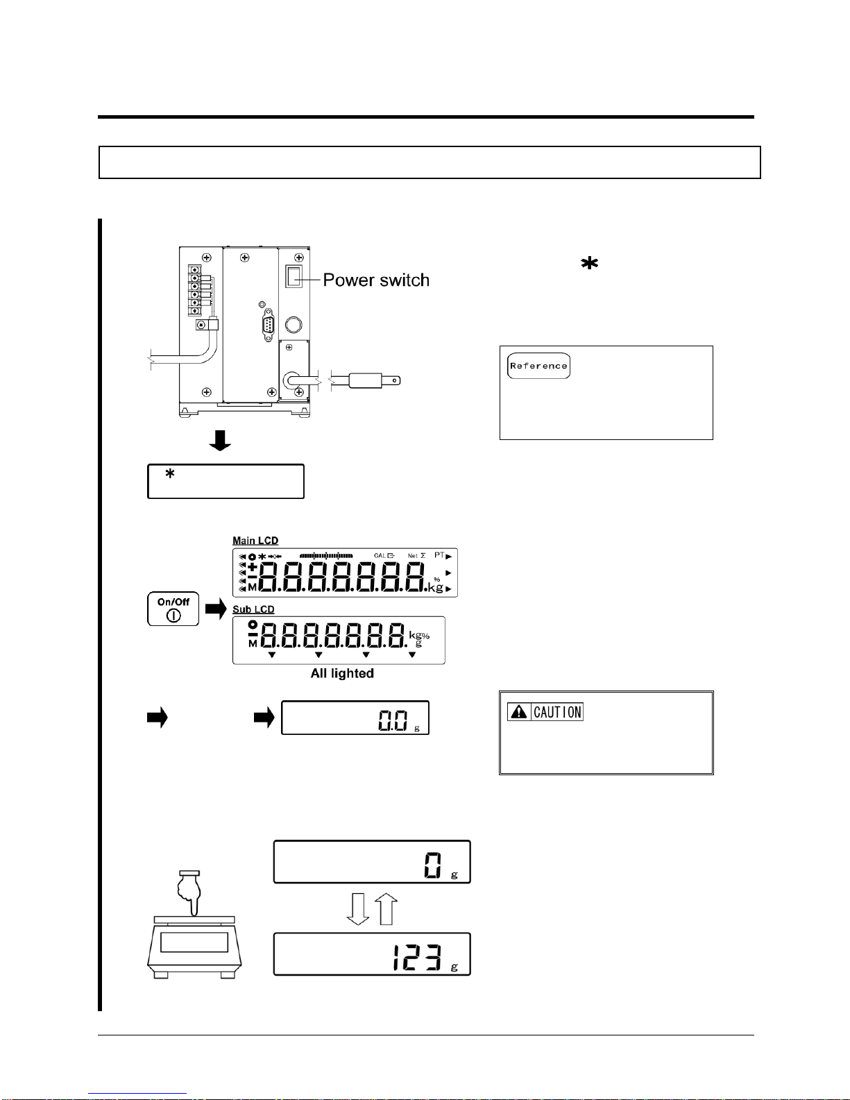
2-1 Turning on / off the power, and checking for the operation
Turn on and off the power for this product.
1
Turn on the power.
Turn on the power for the power
supply box.
An asterisk ( ) mark lights on the
main LCD, and the product becomes
standby status.
Setting the direct start function to
“ON” shifts to the state of
weighing automatically.
2
Turn on the power for the scale.
“Self-check”
The sub LCD is installed only on the i03.
Push the [On/Off] key.
All displays on the main and sub
LCDs light, followed by the
self-check of the scale. During the
self-check, the LCD displays
automatically change.
Completion of the self-check is
followed by the weight scale mode.
Do not push any key during the
self-check.
3
Scale operation check
Press the weighing pan lightly to
check if the indication changes.

2Basic usage FZ-Ex series operetion manual
-8-
4
Turn off the power for the scale.
Push and hold the [On/Off] key.
The product becomes standby status
and the symbol ( ) lights.
Pushing and holding the [On/Off]
key obtains the standby status
from any operation status.
2-2 Making a zero adjustment
Adjusting the indication to zero is called “zero adjustment.”
1
Check the top of the weighing pan.
Make sure that nothing is placed on the top
of the weighing pan.
2
Make a zero adjustment.
Push the [Zero] key.
Displays on the main LCD become zero and the
symbol “ ” lights.
(1)
It might be possible that the “Zero adjustment” cannot not be performed when an object
is placed on the weighing pan. In that case, make the “tare weight subtraction” referring
to the “Weighing an object placed on a container (tare)”
(2)
Stability waiting during the zero adjustment can be set using the function item “Stability
waiting.” In the case the “Stability waiting” is set, the symbol “M” flashes during the
stability waiting. For its setting method, refer to “3 Functions related to the operation.”
(1)
“Stability waiting” setting function of the above (2) can not be use.
FZ-Ex series operetion manual 2Basic usage
-9-
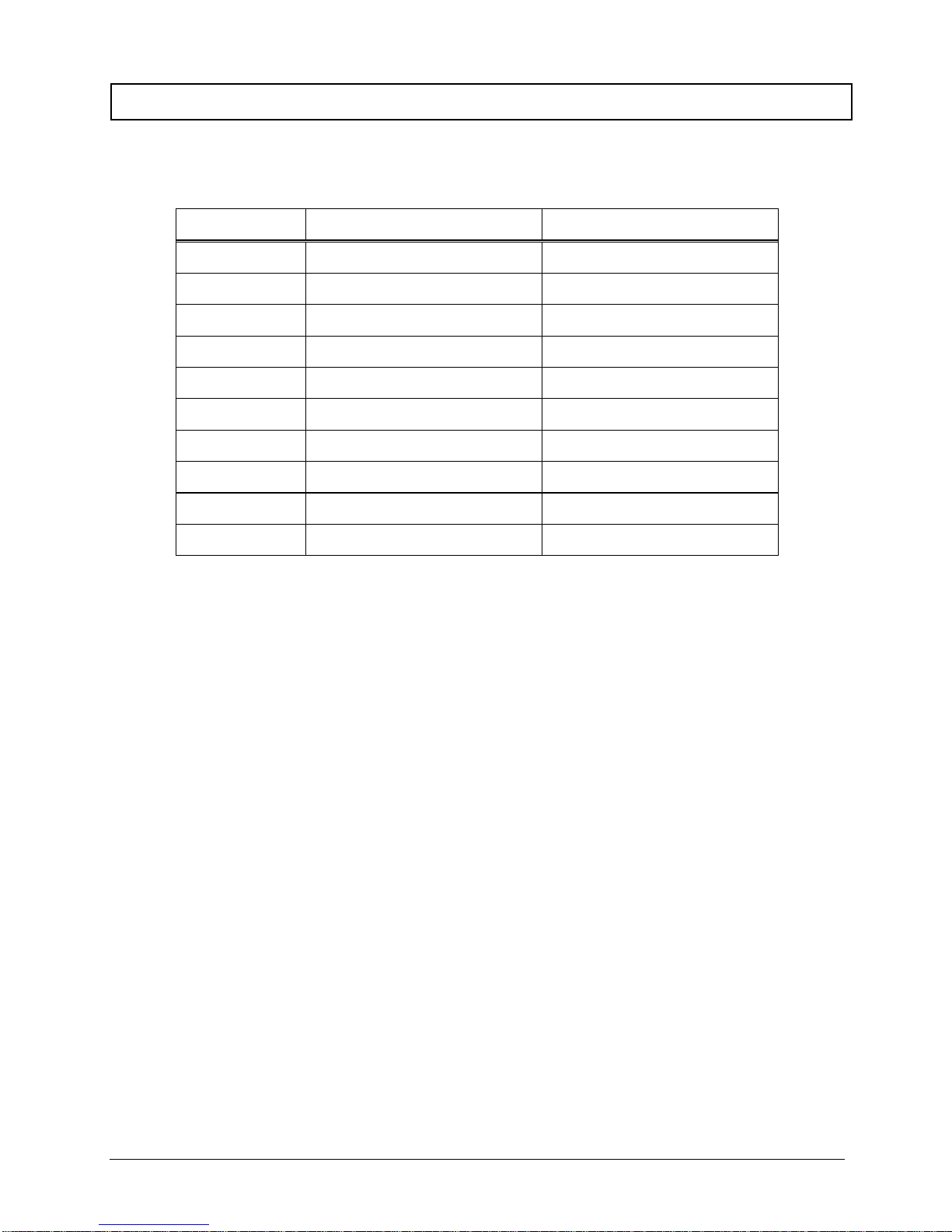
2-2-1 Zero adjustment range when in use
Zero adjustment range when in use is limited in this product.
The available zero adjustment range when in use is shown below:
Model
Lower limit (g)
Upper limit (g)
FZ623Ex
-9.3
9.3
FZ3202Ex
-48
48
FZ6202Ex
-93
93
FZ15001Ex
-225
225
FZ30K0.1GEx
-450
450
FZ60K0.1GEx
-900
900
FZ100K1GEx
-1500
1500
FZ200K1GEx
-3000
3000
FZ150K1GFEx
-2250
2250
FZ300K1GFEx
-4500
4500

2Basic usage FZ-Ex series operetion manual
-10-
2-3 Weighing an object placed on a container (tare)
When weighing an object to be weighed with the object placed on a container (tare), the
weight of the container must be subtracted from the total weight to get the actual weight of the
object to be weighed. This is called “tare weight subtraction.”
1
Place a container on the weighing pan.
The weight of the container is displayed.
2
Perform the tare weight subtraction.
Push the [Tare] key.
The indication changes to zero and the “Net”
symbol lights.
The indication changes to zero and the
“ ” symbol lights.
3
Place an object to be weighed on the
container.
The net weight of the object to be weighed
alone is indicated.
4
Clear the tare weight.
or
Remove the tare and the object to be weighed
from the weighing pan.
[Push the [Zero] key or the [Tare ] key.
The indication changes to zero and
the“ ” symbol goes out.
(1)
Performing the tare weight subtraction narrows the weighing range as much as the amount
of the tare weight mass (tare weight).
Weighable range = weighing capacity - tare weight
(2)
Stability waiting during the tare weight subtraction can be set using the function item
“Stability waiting.” In the case the “Stability waiting” is set, the symbol “M” flashes during the
stability waiting. For its setting method, refer to “3 Functions related to the operation”.
(3)
When using a tare whose tare weight is already known, the tare weight subtraction can be
performed in advance by inputting its tare weight (preset tare weight subtraction). For its
setting method, refer to “5 User information setting”.
(4)
When turning on the power placing a tare that exceeds the zero adjustment range at the
time of power supply, the tare weight subtraction is executed.
(1)
Operation of the above (4) is not performed.
This manual suits for next models
9
Table of contents
Other Shinko Denshi Scale manuals

Shinko Denshi
Shinko Denshi CT603 User manual

Shinko Denshi
Shinko Denshi PF-R150 User manual

Shinko Denshi
Shinko Denshi HTR-80CE User manual

Shinko Denshi
Shinko Denshi LN 223CE User manual

Shinko Denshi
Shinko Denshi LN 423 User manual

Shinko Denshi
Shinko Denshi LF124R User manual

Shinko Denshi
Shinko Denshi FS623 User manual

Shinko Denshi
Shinko Denshi AZ Series User manual


