Shinko Denshi HTR-80CE User manual

270011M21
T u n i n g F o r k A n a l y t i c a l B a l a n c e
HT/HTR-CE
Series
Operation Manual
SHINKO DENSHI CO., LTD.
IMPORTANT
To ensure safe and proper use of the balance, please read this
manual carefully.
After reading this manual, store it in a safe place near the balance, so
you can review it as needed.
PREFACE
Thank you for purchasing an HT/HTR Series electronic balance.
The HT/HTR Series is a new balance equipped with a high-precision tuning fork sensor
mechanism. It windshield is made of antistatic plastic, helping to reduce its weight, and the
balance is equipped with a variety of functions such as parts counting, percentage weighing,
gravimeter and limit functions that are helpful in weighing fixed amounts. This multifunctional
balance employs a user-friendly program, and the keys are arranged in a way that makes the
balance easy to operate. In addition, the fluorescent display is eye-friendly, and the balance’s
high-speed and stable performance improves your work efficiency.
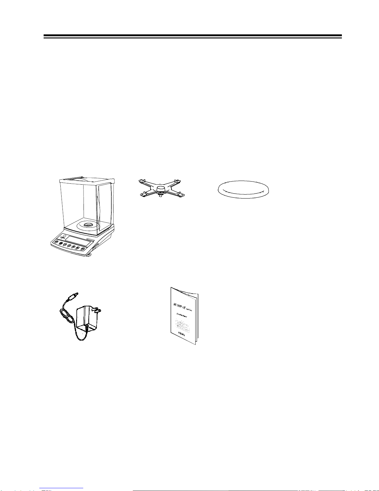
Check for the following accessories before use.
If any items are found to be missing or damaged, immediately contact local dealer.
(1) Main Unit (2) Pan Base (3) Pan
(4) AC adapter (5) Operation manual

1
Contents
Contents.......................................................... 1
1Precautions Relating to Use.................... 3
2Names of Component Parts.................... 7
2.1 Main Unit...................................... 7
2.2 Operation Keys ............................ 8
2.3 Displayed Signs ........................... 9
3Installation of the Balance..................... 10
4Basic Operation..................................... 11
4.1 Power On/Off ............................. 11
4.2 Weighing .................................... 11
4.3 Zero Adjustment......................... 11
4.4 Tare (pan) .................................. 11
4.5 Set a Gross Weight.................... 12
4.6 Single-touch Response Setting . 12
4.7 Data Output................................ 13
4.8 Hanging Measurement .............. 13
5Function 1 ............................................. 15
5.1 Setting and Check ..................... 15
5.2 Description of Function 1 ........... 16
5.3 Specific Gravity Setting.............. 19
5.4 Limit/Addition Functions............. 19
5.5 Interface ..................................... 20
6Function 2 ............................................. 21
6.1 Calling and Setting..................... 21
6.2 Description of Function 2 ........... 21
7Weighing and Measurement Modes ..... 22
7.1 Weighing and Measurement
Modes ........................................ 22
7.2 Weighing Machine ..................... 22
8Parts Counting ...................................... 23
9Percentage Weighing............................ 25
9.1 Set a reference weight by
weighing an actual sample ........ 25
9.2 Set a reference weight by
entering a value ......................... 26
10 Unit Converting ...................................... 27
11 Gravimeter .............................................28
11.1 Measurement procedures for
specific gravity............................28
11.2 Entering water temperature or
the specific gravity of the media. 30
12 Addition Function ................................... 32
12.1 Cumulate Function .....................32
12.2 Net Addition Function .................33
13 Limit Function ........................................35
13.1 Setting the Limit Function........... 35
13.2 Judgment and Saving.................35
13.3 Display of Judgment Results...... 35
13.4 Judge by Absolute Values.......... 36
13.5 Judge by Deviation Values......... 39
13.6 Bar Graph for the 2-point Scale .43
14 Calibration and Span Test for the
Balance..................................................44
14.1 Span Adjustment with Built-In
Weights....................................... 44
14.2 Span Adjustment with External
Weight ........................................44
14.3 Span Test with Built-In Weights . 45
14.4 Span Test with External Weight .45
14.5 Calibration of Built-In Weights.... 45
14.6 Entry of Weight Error..................47
14.7 Advice CAL and Full-automatic
Span Adjustment ........................48
14.8 Auto Repeatability
Measurement (ARM) ..................48
15 Date and Time Setup............................. 49
15.1 Time Setup .................................49
15.2 Date Setup..................................49
16 Various Functions .................................. 50
16.1 Auto Backlight OFF ....................50
16.2 Set Unit....................................... 50
16.3 Date Display ...............................50
16.4 Time Stamp Output ....................50
16.5 Direct Start..................................50
16.6 Interval Output Function .............51
16.7 Input of ID No. ............................52

2
17 Input/Output Functions.......................... 53
17.1 RS232C Output.......................... 53
17.2 Output to Peripherals................. 56
17.3 Type of Communication Texts ... 57
17.4 Output Data................................ 57
17.5 Input Commands........................ 61
17.6 Special Format Output............... 67
18 Use Printers .......................................... 69
18.1 Setting up the Printer ................. 69
18.2 Outputting calibration results ..... 69
18.3 Output of Measurement Data in
Compliance with ISO/GLP/GMP 69
19 Output in Compliance with
ISO/GLP/GMP .......................................70
20 Removing the Windshield Door ............. 73
20.1 Removing the Windshield Door.. 73
20.2 Caring for the balance ................ 73
21 Troubleshooting ..................................... 74
22 Specifications.........................................75
22.1 Basic Specifications ................... 75
22.2 Weighing Capacity and
Minimum Readability by Unit...... 76
23 Unit Conversion Table ...........................77
3
1 Precautions Relating to Use
This Section “Precautions Relating to Use” sets forth precautionary notes that the user
should observe in order to prevent physical injury to the user and/or damage to property.
The nature of problems that may result in the event of improper operation, and
consequential effects on the quality and performance of the balance, are indicated under
the two categories of “Caution” and “Recommended,” and explained using symbols.
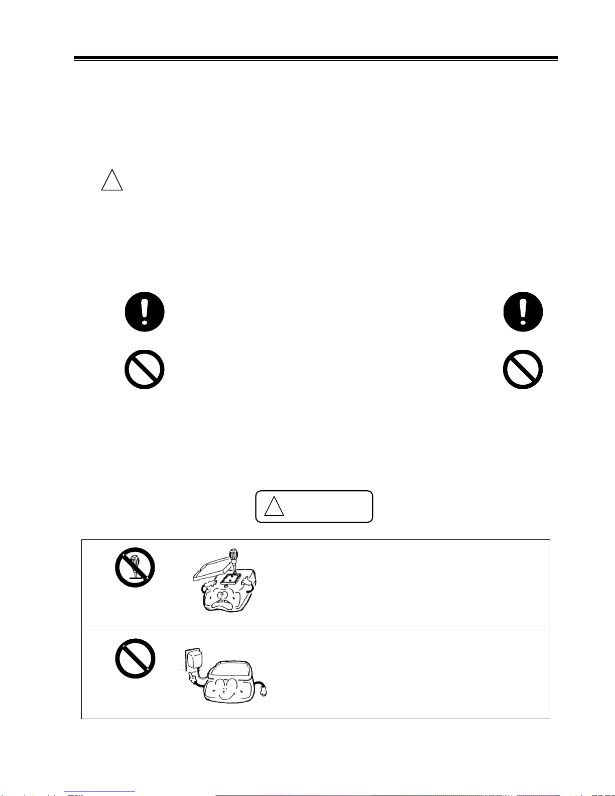
! Caution
This is a category to indicate improper handling that may
cause physical injury or severe damage to property. Be
sure to follow the directions for safe use to avoid serious
consequences.
Recommended This term indicates steps that the user should take to
ensure the quality and reliability of the balance.
Meanings of Symbols Each symbol is accompanied by an instruction.
Mandatory Symbol
Indicates a “mandatory” action that should
be executed without fail.
Example
Check Level
Prohibitive Symbol
Indicates a “prohibited” action that must
not be executed.
Example
Do Not Use
Do not disassemble or modify the unit.
• Could cause malfunction.
• In case of malfunction do not disassemble the
unit. Contact our local dealer.
Only AC power should be used.
Only use the dedicated AC adapter.
• Use of other types of power or adapters may
result in heat generation or malfunction of the
balance.
!Caution!
Do Not Deviate
from Ratings
Do Not
Disassemble
4
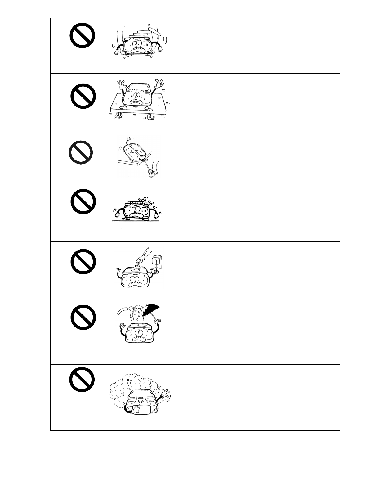
Do not move the balance when a sample is
loaded.
• The loaded sample may fall off the pan and cause
an injury.
Do not place the balance on an unstable base
or use the balance in a location where it may
be subjected to shock.
• The loaded sample may fall off the pan.
• Accurate measurement may be rendered
impossible.
Do not lay the AC adapter cable on the surface
of the passage.
• Somebody may trip on the cable, causing the
balance to fall off, thereby causing injury and/or
damage to the balance.
Do not use the balance with its adjusters
lifted.
• The balance will become unstable, preventing
accurate measurement.
Do not touch the AC adapter or the balance
with wet hands.
• Could result in an electrical shock.
Do not expose the balance to rain or water.
• Could cause an electrical shock or short circuit.
• The balance will corrode and malfunction.
Do not use the balance in a dusty
environment.
• Could cause an explosion or fire.
• Could cause a short circuit or interfere with the
balance’s electrical conductivity, causing it to
malfunction.
Do Not Move
Do Not Drop
Do Not Leave
Afloat
Do Not Touch
with Wet Hand
Do Not Expose
to Water
Do Not Use
Do Not Expose
to Dust
5
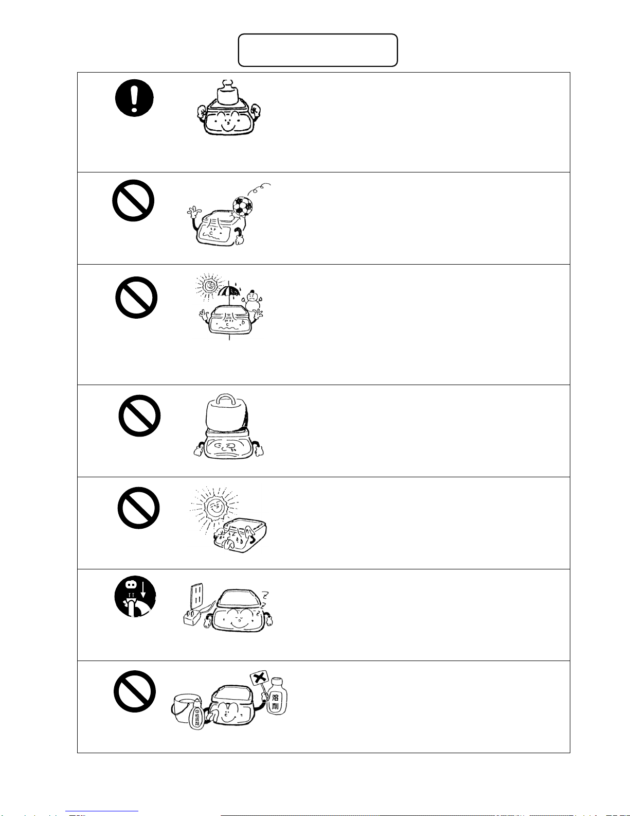
Calibrate the balance after installation or
relocation.
• Measurement values may contain errors,
preventing accurate measurement from being
conducted.
Avoid applying excess force or impact to the
balance.
• Place the sample to be measured on the balance
carefully to prevent breakage or malfunction.
Do not use the balance in a location were it may
be subjected to abrupt changes in ambient
temperature or humidity.
• Accurate measurement may be rendered
impossible.
• Use the balance in an ambient temperature range
of 10°C to 30°C and with 80% or lower relative
humidity.
Do not leave the balance overloaded. (When it
is overloaded, (o-Err) is displayed.)
• Take down the loaded sample immediately to
prevent breakage or malfunction.
Do not use the balance in a location where it is
subject to direct sunlight.
• The indications would be illegible.
• An internal temperature increase in the balance
may lead to inaccurate measurement.
If the balance is to be unused for an extended
period of time, unplug the adapter.
• This conserves power and prevents deterioration.
Do not use volatile solvents for cleaning.
• The body may be distorted.
• To clean the unit of stains, use a piece of dry cloth
or cloth soaked in a small quantity of neutral
detergent.
Recommended
Calibrate Balance
Do Not Apply
Force
Do Not Overload
Do Not Use
Do Not Use
Do Not Use
Unplug Adapter

6
Do not use the balance in a location where it
may be subject to air from an air-conditioning
unit.
• Extreme changes in the ambient temperature may
result in inaccurate measurements.
Do not use the balance on a soft floor.
• When loaded with a sample, the balance may tip or
move, preventing accurate measurements from
being conducted.
Do not use the balance when it is tilted.
• When the balance is tilted, an error may be caused,
preventing accurate measurement from being
conducted. Place the balance on a level surface.
Do Not Use
Check Level
Do Not Use

7
2 Names of Component Parts
2.1 Main Unit
Windshield (door)
Pan
Windshield ring
Level
Operation ke
y
Liquid crystal display
RS-232C connector
(D-SUB9P)
Connector for peripheral
devices
(DIN8P)
* Replace the connector cap
when not using AC power.
AC adapter connector
Adjuster
(Adjustable leg)
Fixed leg
Cover of hanging
hook
8
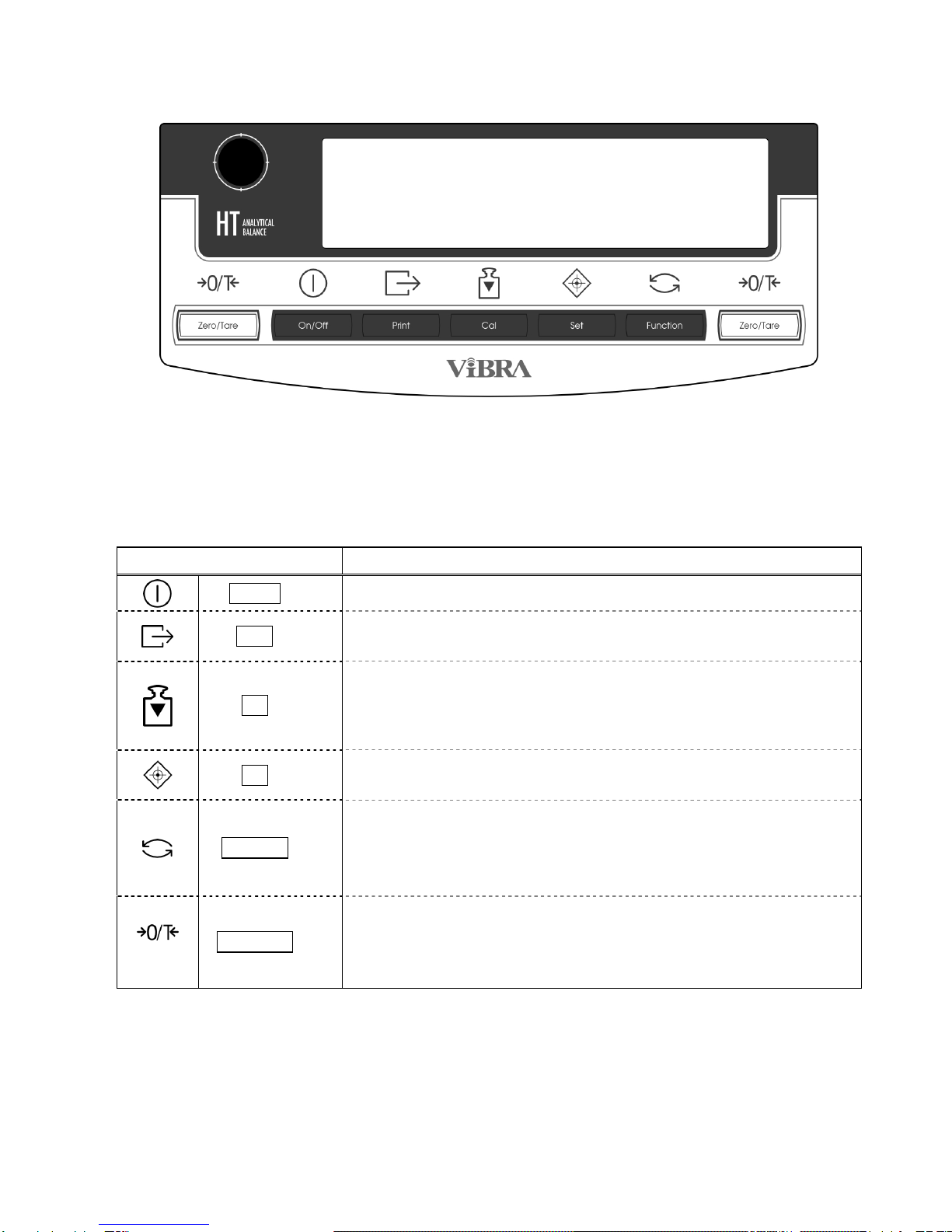
2.2 Operation Keys
Operation key Function
On/Off key Turns the balance on or off.
Print key Starts output.
Pauses the setting and input operation.
Cal key
[Short press] Switches to the span adjustment and span test
modes.
[Continuous press] Starts automatically repeatable
measurements.
Set key [Short press] Toggles the response mode.
[Short press] Stores the settings.
Function key
[Short press] Toggles the weighing modes.
[Short press] Used to enter numerical values.
[Short press] Used to select a function to set.
[Continuous press] Calls functions.
Zero/Tare key
[Short press] Used for zero-setting or sets the display to
zero by tare range.
[Short press] Used to enter numerical values.
[Short press] Used to select a function.
9
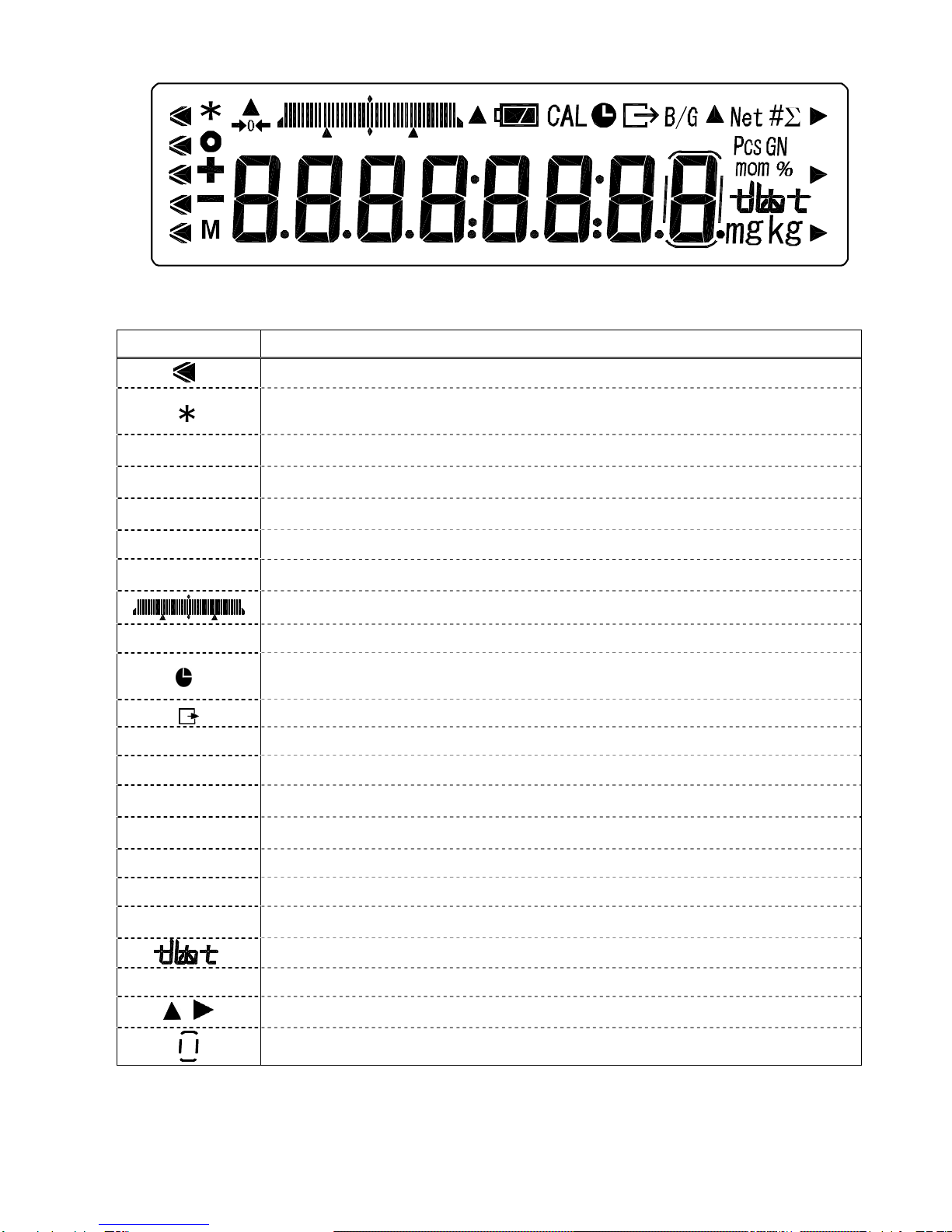
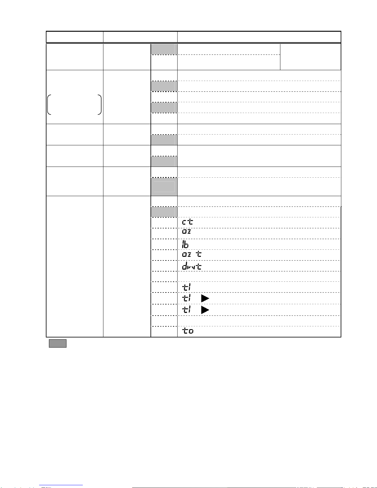
2.3 Displayed Signs
2.3.1 Displayed signs
Display Description
Displays the judgment results when the (five-point) limit function is enabled.
Displayed when the balance is in standby mode.
Indicates that the addition function is enabled for accepting an additional load.
○Indication of stable balance (If this light is off, the balance is unstable.)
+Sign for sample addition when parts counting is performed
-Minus
M Display of set values from memory (If it is flashing, the value is being saved.)
→0←Zero-point
Bar graph (Refer to Hints on page 43).
CAL Displayed when calibration and Advice CAL are enabled.
Lights up when date/time is being set or displayed.
Blinks during interval output.
Displayed when data is output in compliance with ISO/GLP/GMP.
B/G Gross weight
Net Tare sign
#Unit converting
ΣDisplays a sum total.
Pcs Parts counting
mom Momme
%Percentage weighing
Displays the selected unit.
mg Milligram, gram
, Displayed according to the function.
Lights up only when the auxiliary scale interval is being displayed.

10
3 Installation of the Balance
1. Attach the pan base and pan.
Attach the pan base and pan to the main unit as shown in the figure.
2. Level the Balance.
Turn the adjuster so that the air bubble in the level gauge is within the circle.
3. Connect the AC adapter.
Connect the AC adapter to the balance.
After the balance has been moved, open the windshield door to allow it to
adapt to the ambient temperature for stable measurement.
In addition, allow five minutes after turning on the power for the balance to
warm up.
Pan base
(Turn the knob located in
the center to attach it.)
Pan
Adjuster
AC adapter connector
Position of the air
bubble in the level

11
4 Basic Operation
4.1 Power On/Off
Press the On/Off key to turn the power on and off.
The * sign is displayed when the balance is powered by the AC
adapter and is in standby mode.
When an object is lying on the pan, the blinking [ on 0 ] is displayed. In such cases,
remove all the objects on the pan.
If a unit other than “g” (gram), “mg” (miligram) or “ct” (carat) is selected as Unit A,
the unit automatically changes to “g”.
4.2 Weighing
Place a sample on the balance and close the windshield door.
A circle will be displayed after the measurement has stabilized.
Read the measurement while the circle is displayed.
The circle will not be displayed or will flicker if the balance is
subject to disturbance such as vibration. Take appropriate
measures to stabilize the balance.
The bar graph indicates the current load in relation to the
balance’s weighing capacity. As the load approaches the
weighing capacity, the bar extends towards the right.
When the weight of an object exceeds the balance’s weighing
capacity, [o-Err] is displayed.
If the pan is removed and the zero-point falls below the original
zero-point, [u-Err] is displayed.
4.3 Zero Adjustment
Press the Zero/Tare key.
Wait until the display becomes stable (the M sign
flashes), and set the display to “0”.
While the zero point is accurately maintained, the
[→0←] sign is displayed.
4.4 Tare (pan)
Place the tare (pan) on the balance and press the
Zero/Tare key.
When the display becomes stable, “0” is displayed.
(Continued on next page.)
On/Off
Stable
Unstable
Zero Weighing
capacity
Bar graph

12
This operation is called “tare” and “Net” is displayed
while the weight of the pan is being set.
After the weight of the pan has been set, if a sample is placed in the container the balance will
display the weight (net weight).
* When a tare range is set, the weighing capacity is reduced accordingly.
Weighing capacity = original weighing capacity – pan weight
Even after the weight of the pan has been set and the display is set to “0,” the value indicated
by the bar graph includes the pan weight.
4.5 Set a Gross Weight
Press the Function key while the weight of the pan is
being set.
The gross weight, which is the sum of the pan weight
and the weight of the sample put in it, is displayed.
The B/G sign is displayed while the gross weight is
being displayed.
Pressing the Function key will toggle the display
between net weight and gross weight. (Unit B (net
weight) is also displayed if it has been selected.)
Caution:
1. A gross weight can only be displayed when the balance functions as a weighing machine.
2. When a gross weight is displayed, you cannot set a tare range. You can only adjust the
zero-point.
4.6 Single-touch Response Setting
This function allows you to switch the response of the balance with a single touch of the Set
button.
The balance will be subject to different levels of vibration depending on where it is placed.
Adjusting the balance’s response according to the magnitude of vibration reduces the variation
in its display and the time required for the display to stabilize.
Pressing the Set key once displays the current settings ([norMAL] etc.).
Pressing the Set key again toggles the display between [norMAL→SLoW→FASt].
After the balance settings have been completed, the display automatically returns to the
weighing mode.
This function corresponds to the settings [5. rE. *] and [6. Env. *] of Function 1, and the
settings in Function 1 are also changed at the same time.
(Continued on next page.)
(Unit B)
13
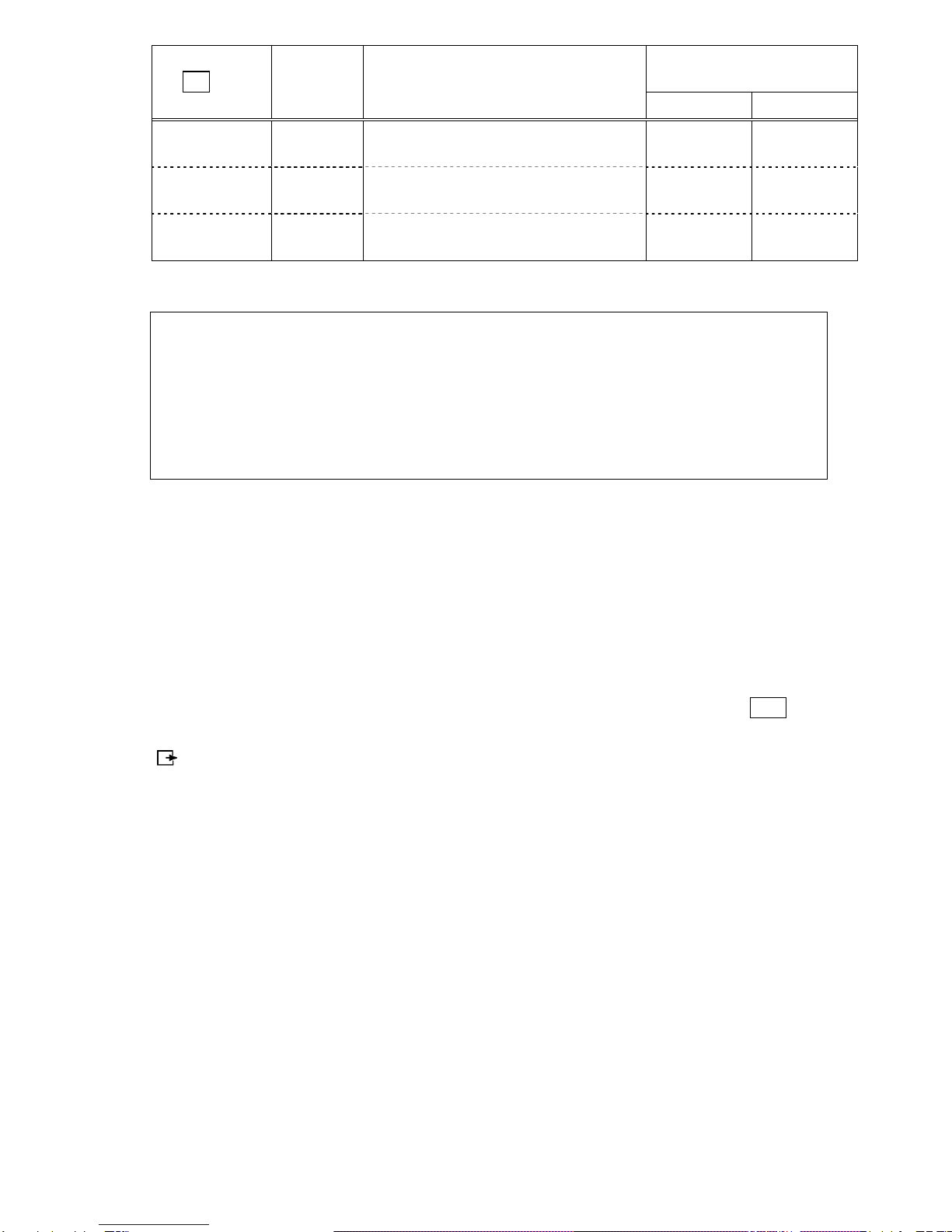
Corresponding settings in
Function 1
Set key Meanings Description
6. EnV. 5. rE.
FASt FAST
The balance responds quickly but it
is easily affected by vibration 0 1
norMAL NORMAL The balance’s response is
somewhere between fast and slow 0 3
SLoW SLOW
The balance responds slowly but is
not easily affected by vibration 1 3
(Refer to “Section 5: Function 1” on page 15 for further information on Function 1.)
In [6. EnV. *], [0] indicates a fast response. Use this setting when the balance is
subject to a low level of vibration.
[1] indicates a slow response. Use this setting when the balance
is subject to a high level of vibration.
In [5. rE. *], [1] indicates the fastest response. Use this setting when the
balance is subject to a low level of vibration. As the number
approaches [5], the balance’s response becomes slower but it is
also less affected by vibration.
* To adjust the response more finely, use Function 1.
Caution
This function is unavailable when the gravimeter or addition function is enabled.
4.7 Data Output
Measured data and GLP data can be output to a personal computer, printer, or similar device
via the built-in RS-232C interface. In the factory default setting, pressing the Print key once
will output the current measured value when the measurement becomes stable.
[] is displayed while the data is being output.
Refer to “Section 5.5: Interface” on page 20 for further information on the output settings.
4.8 Hanging Measurement
The balance is equipped with a hanging hook to suspend a hanging pan for weighing.
Perform hanging measurements when weighing electromagnetic, electrostatic, or
high-temperature samples that cannot be accurately weighed on the normal pan.
Remove the pan and gently tilt the balance backward.
Take care that the door does not fall off.
(Continued on next page.)

14
Caution
1. Tools (hanging pan etc.) suspended from the hook are regarded as a tare (pan). Weights
equal to the weighing capacity cannot be measured.
Measurable weight = Weighing capacity – Total weight of tools suspended
2. Be sure to close the cover of the hanging hook when not in use to prevent dust from
entering the balance.
Hook for hanging
measurements
Loosen the screw and turn the
cover 90°. Then tighten the
screw to secure the cover.
15
5 Function 1
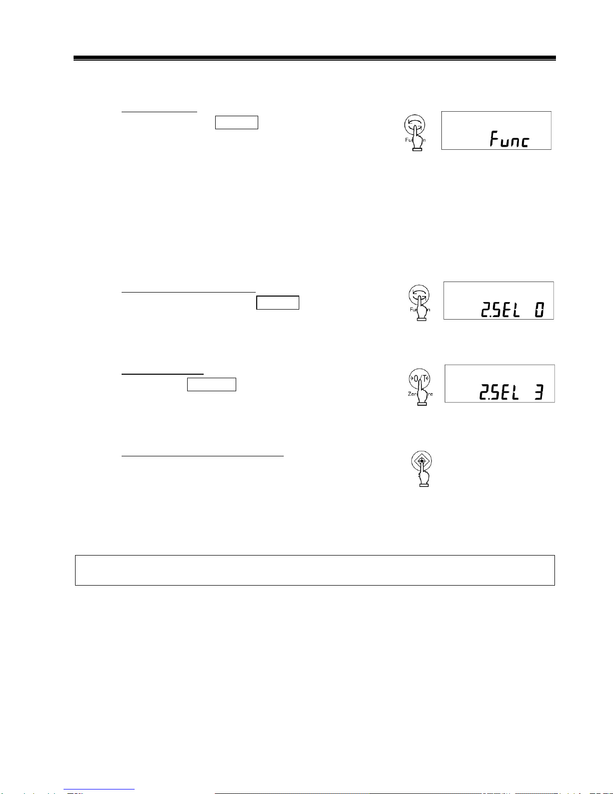
5.1 Setting and Check
1. Call Function 1.
Press and hold the Function key for a few seconds.
When the display is changed to [Func] , release the
key.
The display switches to the Function 1 setting
screen and the first setting item [1. SEt 1] is
displayed.
(Refer to “Section 5.2: Description of Function 1” on
page 16).
2. Select the next setting item.
Every time you press the Function key, you are
moved one item forward.
3. Change settings.
Pressing the Zero/Tare key toggles the right-hand
value. Choose the appropriate setting.
4. Complete the setting of functions.
Press the Set key, or press the Function key
several times until the balance enters
measurement mode.
The setting of functions is completed, and the
balance goes back into measurement mode.
The setting values of Function 1 are stored after the power is turned off. Therefore, you do not
need to reenter the settings the next time the balance is used unless you wish to change them.
Continuous
Press
Key released

16
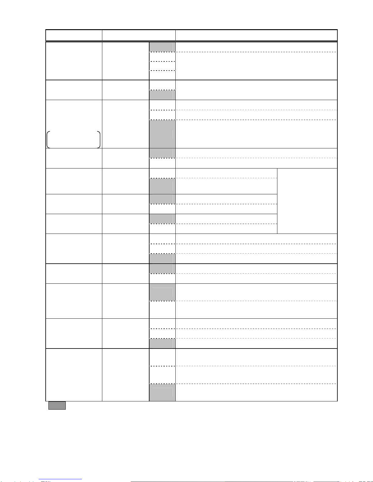
5.2 Description of Function 1
Contents of Function 1 (1/3)
Item Set Value Description
1 Weighing machine (only supports weight measuring)
2 Parts counting (parts counting and weight measuring)
3 Percentage weighing (weight percent measuring and
weight measuring)
4 Unit converting (coefficient multiplying and weight
measuring)
5 Gravimeter (Measuring specific
gravity of a solid)
Weighing Mode 1. SEt
6 Gravimeter(Measuring specific
gravity of a liquid)
→Proceed to
“Section 5.3:
Specific Gravity
Setting.”
0 Disable additional functions
1 Addition function ⇒[26. Ad.M]
2 Limit function
Additional
Functions 2. SEL
3 Addition and limit functions
Refer to “Section
5.4, Limit/Addition
Functions.”
0 Disable
Auto-Zero
(Zero Tracking) 3. A.0 1 Enable
2
3
Stability
Judgment 4. S.d.
4
Wide (Mild)
Narrow (Strict)
0 Measurement by consecutive weighings
1
2
3
4
Response Speed 5. rE.
5
Fast
Slow
0 Use when the balance is subject
to a low level of vibration
Vibration
Response
Setting
6. EnV.
1 Use when the balance is subject
to a high level of vibration
Linked to the
single-touch
response setting
function.
0 Stop input/output
2 Numeric 7-digit format
3 Extended 7-digit numeric format
Interface 7. I.F.
4 Special formats
→Refer to
“Section 5.5:
Interface.”
factory setting.
17
Contents of Function 1 (2/3)
Item Set Value Description
41 Special formats 1
Special Formats 7. I.F. 42 Special formats 2
Displayed when
[7. 1F 4] is
selected.
0 Disable the Cal key.
☆A 1 Span adjustment using built-in weights
2 Span test using built-in weights
☆B 3 Span adjustment with external weight
Span Adjustment
Span Test
HT Series 0,3,and 4
can be selected only.
8. CA.
4 Span test with external weight
0 No display
Bar Graph 9. b.G. 1 Displays the bar graph
0
Auto Power Off A. A.P. 1 Not Available in HT(R)-CE
0 Disable
Auto Backlight
OFF Function b. A.b. 1 Enable (The backlight goes off if the balance is not
used for about three minutes.)
1 [mg]
2 [g]
4 [ ] [carat]
5 [ ] [ounce]
6 [ ] [pound]
7 [ ] [troy ounce]
8 [ ] [penny weight]
9 [GN] [grain]
A [ ] [tael](Hong Kong)
b [ ,Upper right] [tael](Singapore,Malaysia)
C [ ,Lower right] [tael](Taiwan)
d [mom] [momme]
Unit A C1. u.A
E [ ] [tola]
factory setting. ☆A is factory setting of HTR series. ☆B is factory setting of HT series.
18
Contents of Function 1 (3/3)
Item Set Value Description
0 None
1
|
Unit B C3. u.b
E
The settings of [1, 2, 4-E] are the same as those of
Unit A.
0 Disable.
Auxilliary
indication setting d. Ai. 1 Enable
☆B 0 Disable
1 Advice CAL
Advice CAL and
Full-automatic
Span Adjustment
HT series 0, 1 only
be selected.
E. Ad.C.
☆A 2 Full-automatic Span Adjustment (Displayed only with
the HTR series)
0 Disable
Compliance with
ISO/GLP/GMP F. GLP 1 Enable
0 Disable
Output of Span
Adjustment and
test results
F1. out 1 Enable
0 Disable
Data compliant
with GLP F2. od. 1 Enable
1 English
Printed
Language F3. P.F. 2 Japanese (Katakana)
Displayed when
[F. GLP1] is
selected.
1 Output in Year-Month-Day format.
2 Output in Month-Day-Year format.
Date Display G. dAtE
3 Output in Day-Month-Year format.
0 Disable
Time Stamp
Output H. t.o. 1 Outputs time together with measurement data.
0 The balance enters standby mode when the AC
adapter is plugged in.
Direct Start n. d.St.
1 The balance is turned on when the AC adapter is
plugged in.
0 Always OFF
1 ON
Backlight P. b.L.
2 ON
1 No output when an auxilliary scale interval is being
displayed
2 Output in the mormal format even when an auxilliary
scale interval is being displayed.
Auxilliary scale
interval output
format 3
r. Pr.F.
3 A slash “/“ output in the digit preceding the auxilliary
scale interval.
factory setting. ☆A is factory setting of HTR series. ☆B is factory setting of HT series.
This manual suits for next models
11
Table of contents
Other Shinko Denshi Scale manuals

Shinko Denshi
Shinko Denshi FS623 User manual

Shinko Denshi
Shinko Denshi LN 223CE User manual

Shinko Denshi
Shinko Denshi AZ Series User manual

Shinko Denshi
Shinko Denshi LN 423 User manual

Shinko Denshi
Shinko Denshi PF-R150 User manual

Shinko Denshi
Shinko Denshi FZ623Ex User manual

Shinko Denshi
Shinko Denshi LF124R User manual

Shinko Denshi
Shinko Denshi CT603 User manual


