Magnescale SR87 User manual

SR87, CH33
取付説明書 / Installation Manual / Anbringungsanleitung / 安装说明书
スケールユニット / Scale Unit / Maßstabseinheit / 直线标尺器
お買い上げいただき、ありがとうございます。
ご使用の前に、この取付説明書を必ずお読みください。
ご使用に際しては、この取付説明書どおりお使いください。
お読みになった後は、後日お役に立つこともございますので、必ず保管してください。
本説明書は取付寸法と取付方法についての基本的な項目についてのみ記載したものです。
より詳しい内容については、別売の取扱説明書を参照してください。
Read all the instructions in the installation manual carefully before use and strictly follow them.
Keep the manual for future references.
This manual only contains basic information for the installation dimensions and installation
procedures. Please refer to the Instruction Manual (sold separately) for more detailed information.
Lesen Sie die ganze Anleitung vor dem Betrieb aufmerksam durch und folgen Sie beim Betrieb
des Geräts den Anweisungen. Bewahren Sie diese Anbringungsanleitung zum späteren
Nachlesen gribereit auf.
Diese Anleitung enthält nur grundlegende Informationen über die Installationsabmessungen
und Installationsverfahren. Ausführlichere Informationen entnehmen Sie bitte der
Bedienungsanleitung (getrennt erhältlich).
感谢您惠购本产品。
使⽤之前请务必认真阅读本⼿册,并且严格按照⼿册中的规定操作。将此⼿册留作以后的参
考。
本说明书只对安装尺⼨和安装⽅法的基本项⽬进⾏说明,有关详细内容,请参阅另购的使⽤说
明书。

[For U.S.A. and Canada]
THIS CLASS A DIGITAL DEVICE COMPLIES WITH PART15 OF
THE FCC RULES ANDTHE CANADIAN ICES-003. OPERATION
IS SUBJECT TO THE FOLLOWING TWO CONDITIONS.
(1) THIS DEVICE MAY NOT CAUSE HARMFUL
INTERFERENCE, AND
(2) THIS DEVICE MUST ACCEPT ANY INTERFERENCE
RECEIVED, INCLUDING INTERFERENCE THAT MAY
CAUSE UNDERSIGNED OPERATION.
CET APPAREIL NUMÉRIQUE DE LA CLASSE A EST
CONFORME À LA NORME NMB-003 DU CANADA.

(J) 1
SR87, CH33
安全のために
当社の製品は安全に充分配慮して設計されています。しかし、操作や設置時にまちがった取扱
いをすると、火災や感電などにより死亡や大ケガなど人身事故につながることがあり、危険です。
また、機械の性能を落としてしまうこともあります。
これらの事故を未然に防ぐために、安全のための注意事項は必ず守ってください。操作や設置、
保守、点検、修理などを行う前に、この「安全のために」を必ずお読みください。
警告表示の意味
このマニュアルでは、次のような表示をしています。表示内容をよく理解し
てから本文をお読みください。
警告
この表示の注意事項を守らないと、火災や感電などにより死亡や大ケガなど
人身事故につながることがあります。
注意
この表示の注意事項を守らないと、感電やその他事故によりケガをしたり周
辺の物品に損害を与えることがあります。
警告
· 表示された電源電圧以外での電圧で使用しないでください。火災や感電の原因となる恐れが
あります。
· 濡れた手による取付作業はおやめください。感電の原因となる恐れがあります。
· 本体を分解や改造しないでください。ケガの恐れや、内部回路が破損することがあります。
注意
· 作業を行なう前には、装置の状況をよく確かめて作業の安全を確保してください。
· 電源などの駆動源は必ず切って作業をしてください。火災や事故の原因となります。
· 電源などを入れて動かす場合は、周辺機械や装置などに指を挟まれないように充分注意して
ください。
一般的注意事項
以下は当社製品を正しくお使いいただくための一般的注意事項です。個々の詳細な取扱上の注
意は、本取付説明書に記述された諸事項および注意をうながしている説明事項に従い、正しく
お使いください。
· 始業または操作時には、当社製品の機能および性能が正常に作動していることを確認してから
ご使用ください。
· 当社製品が万一故障した場合、各種の損害を防止するための充分な保全対策を施してご使用
ください。
· 仕様に示された規格以外での使用または改造を施された製品については、機能および性能の
保証はできませんのでご留意ください。
· 当社製品を他の機器と組合せてご使用になる場合は、使用条件、環境などにより、その機能
および性能が満足されない場合がありますので、充分ご検討の上ご使用ください。
2 (J)
SR87, CH33
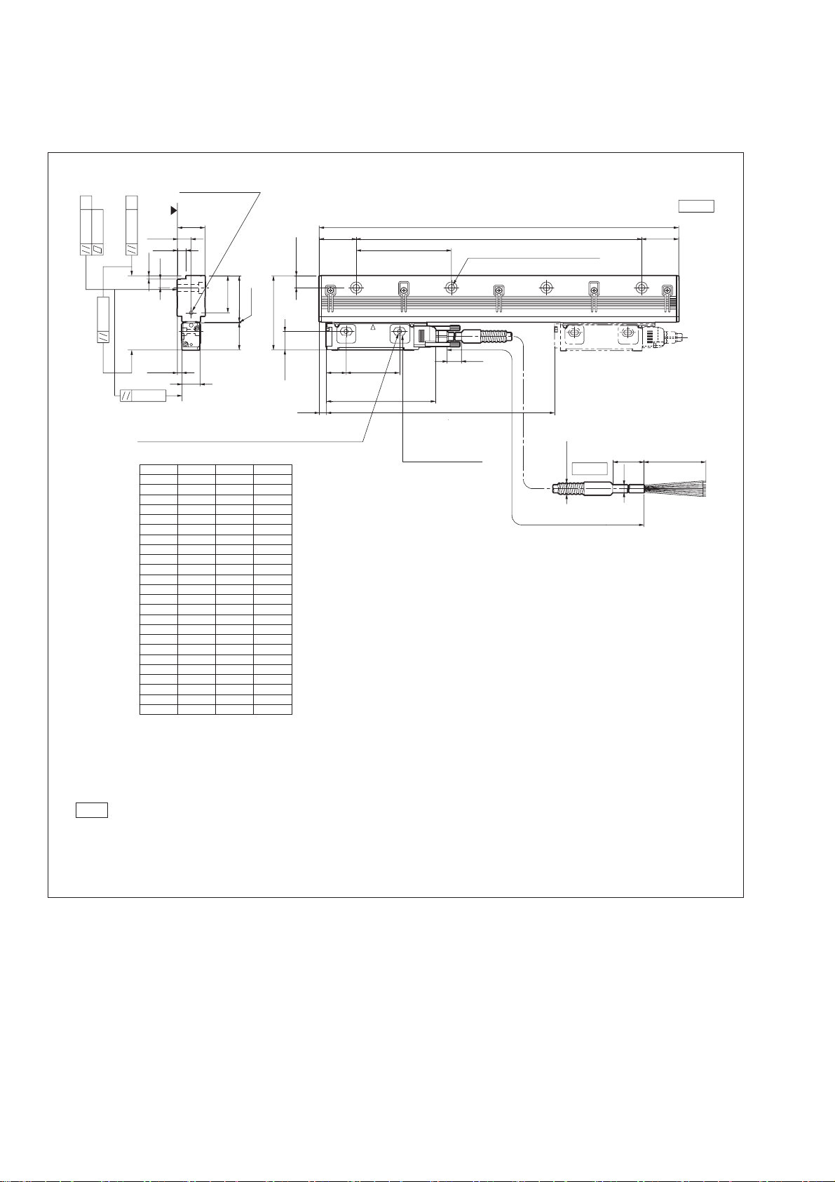
■取付面の許容範囲(平行度、平面度)
L :有効長
CL :ケーブル長
MG :マシンガイド
注意
·▲面を取付面とします。
·図に指示するねじは、標準付属品です。
·有効長(L)を超えてスライダを動かすと破損します。機械の可動長(ストローク)が、有効長(L)の両端から
10mm 以上内側になる設定を推奨します。
32
30
28
26
24
22
20
19
18
17
16
15
14
13
12
11
10
9
8
7
6
5
4
3
n
2300
2100
1900
1800
1700
1600
1500
1400
1300
1200
1100
1000
900
800
600
700
500
400
300
200
3100
2900
2700
2500
3178
2978
2778
2578
2378
2178
1978
1878
1778
1578
1678
1378
1478
1278
1178
1078
978
878
778
478
678
578
278
378
L2
L1L
3040
2840
2640
2440
2240
2040
1840
1740
1640
1540
1440
1340
1240
1140
1040
940
840
740
640
540
440
340
240
140
65
(ø8)
100
CH33
SR87
(ø11.3)
CL=3m,5m,10m,15m
L
115
21 56
7.5
19.5
78
48.5
19
39
28.5
0.1
5±0.2
0.05
0.1
0.05
MG
0.1
MG
9.2
14.5
3.5
(9)
29
1±0.3
100
12.5
39 L2=(100±0.2)×(n‒1)
100±0.2
L1=ML+138
(39)
nø7、ø11 ザグリ 深さ 6.5
単位 :mm
エアパージ用穴
(M5:両端)
六角ザグリ深さ 5
2M6(取付ねじ M420 または M6)
(取付ねじM635)
(J) 3
SR87, CH33
SR87
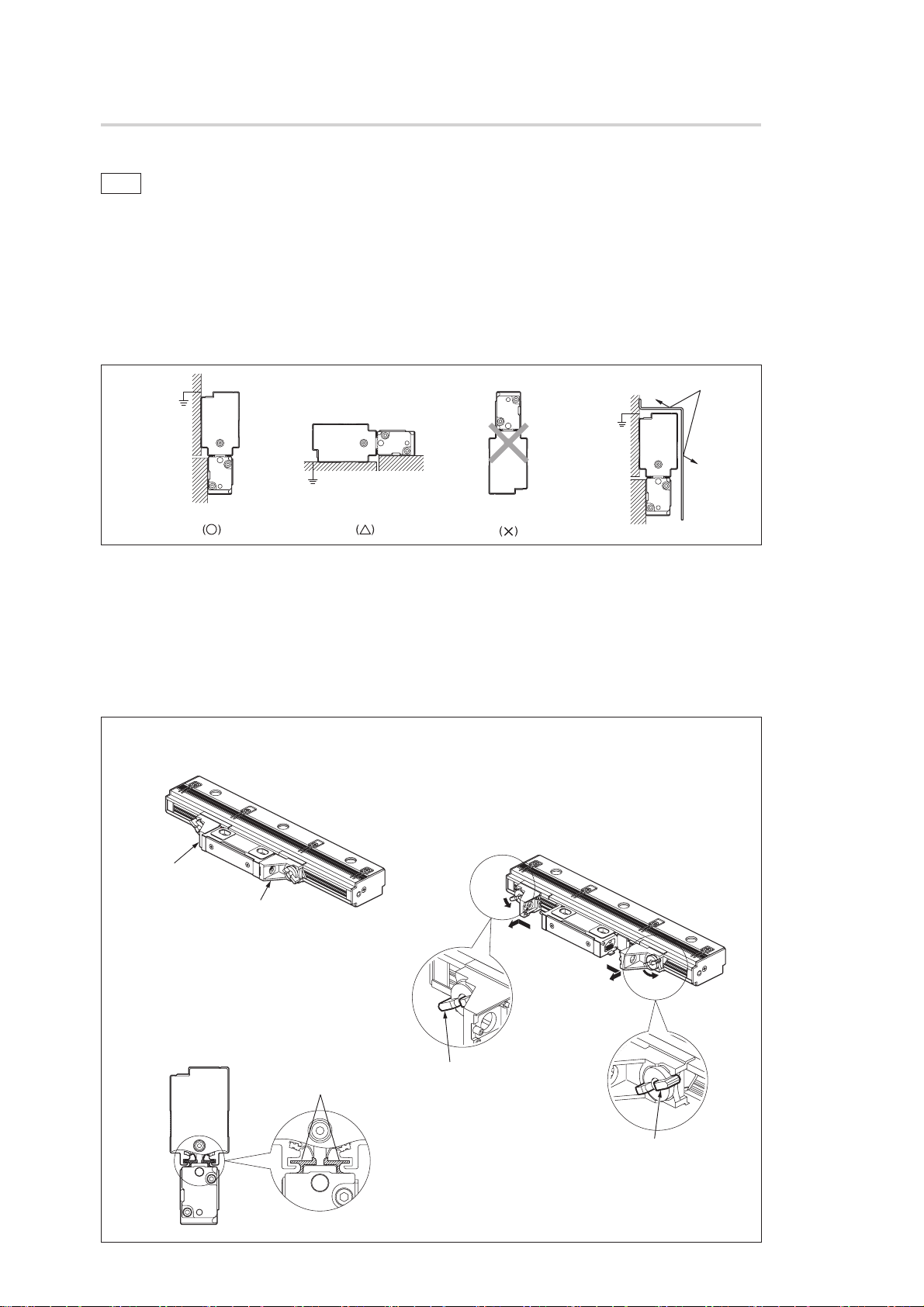
■スケール、スライダの取付の注意
注意
· スケール取付前に電源は投入しないでください。
· スケールは、スケール本体の開口部を下向きにして取付けてください。
下向きが無理な場合は、横向きとしてください。上向きでは取付けないでください。(図 1)
· 取付面はスケールと面接触でアースを取るために、タップ穴の周囲の塗装を剥離してください。
· 有効長(L)を超えてスライダを動かすと破損します。ご注意ください。
· クーラントが直接かかる環境では、クーラントが直接かからないよう、スケールにカバーを
取付けてください。(図 2)
図1
開口部下向き 開口部横向き 開口部上向き
図 2 クーラント
· スライダホルダは、輸送時のスライダ固定用のものです。取付の基準とはなりません。
· スライダホルダは、スライダを固定する直前まで、できるだけ外さないでください。
· スライダホルダを外しても、スライダはスライダに設けられた樹脂フックにより、スケール
本体に対しておおよその位置関係が維持されます。
· 無理にスライダをねじるなどの力を加えると、樹脂フックが外れてしまいます。樹脂フック
が外れたときは樹脂フックを元の位置に戻してから取付作業を行なってください。(図 4 参照)
図3
図4
輸送/固定時の状態
スライダホルダ L
スライダホルダ R
樹脂フック
樹脂フック
スライダホルダの取外し方法
1. ロックの解除
左右のスライダホルダのレバーを反時計方向(イラスト
の位置)に回します。
2. 取り外し
スライダホルダを外側にスライドさせ、スケールから取
外します。
手順 1
手順 1
手順 2
手順 2
レバー
(この位置に回す)
レバー
(この位置に回す)

4 (J)
SR87, CH33
· スケールを取付ける前に、必ず取付面(または取付用ブラケット)のアライメントが規格内
であることを確認してください。
· スケール取付用ブラケットを使用する際は、スケール全長にわたる長さのブラケットを使用
してください。分割されたブラケットを使用する場合でも、必ず取付用ブラケットのアライ
メントが規格内であることを確認してください。
· スケール本体背面が取付基準となります。
· スケール取付ねじは一度に締めず、仮締めし、平行度を出してから規定トルク(図 5 参照)
で締付けてください。
図5
突き当てる
スライダ:M420(2.7N·m)または
M6(9N·m)
スケール:M635(9N·m)
(J) 5
SR87, CH33
取付例
例 1(推奨):ブラケットにスケールとスライダの突き当てを設ける場合
突き当てを設けると、スケールの取付精度が向上します。また、スケールの再取付が簡単にな
ります。
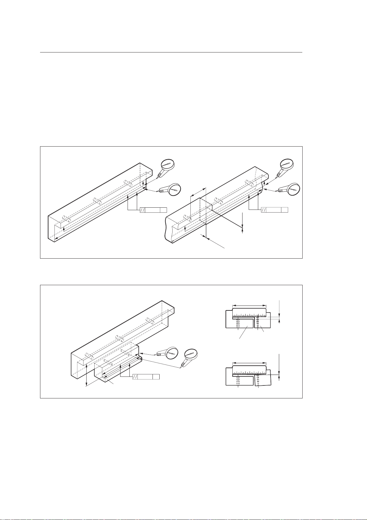
1. スケール用ブラケットのマシンガイドに対する平行度を確認、調整し、固定します。
図のように、分割されたブラケットを使用する場合でも、ブラケット全長で平行度を調整
してください。
図6
単位:mm
50
0.05
MG
0.05
MG
0.05 以下
0.05
以下
または
スケール用
ブラケット
2. スライダ用ブラケットの高さと平行度を確認、調整します。
図7
単位:mm
78±0.3
5±0.2
0.05
MG
78±0.3
78±0.3
0.05 以下
スケール用ブラケット
スライダ用ブラケット
スライダ用ブラケット

6 (J)
SR87, CH33
3. スケールを各突き当て面に突き当てて、取付けます。
図8
例 2:ブラケットにスケールとスライダの突き当てを設けない場合
1. スケール用ブラケットとスライダ用ブラケットのマシンガイドに対する平行度を調整し、
固定します。
スライダ用ブラケットのスケール用ブラケットに対する高さと平行度を調整し、固定しま
す。
図9
単位:mm
78±0.3
5±0.2
78±0.3
0.05
MG
0.05
MG
0.05 以下
スケール用ブラケット
スライダ用ブラケット
スライダ用ブラケット

(J) 7
SR87, CH33
2. スケール背面をダイヤルゲージで測定しながら、スケール背面のマシンガイドに対する平
行度を調整し、固定ねじを締めつけます。
< 測定方法 >
スケール本体背面の取付穴位置付近を測定してください。
図10
0.1
MG
単位:mm
3. スケールとスライダの隙間に、付属品のスペーサ(t=1.0mm)を挿入し、スライダをスケー
ルに突き当てながら、スライダの位置調整を行ないます。
図11
スペーサ(t=1.0mm)
8 (J)
SR87, CH33
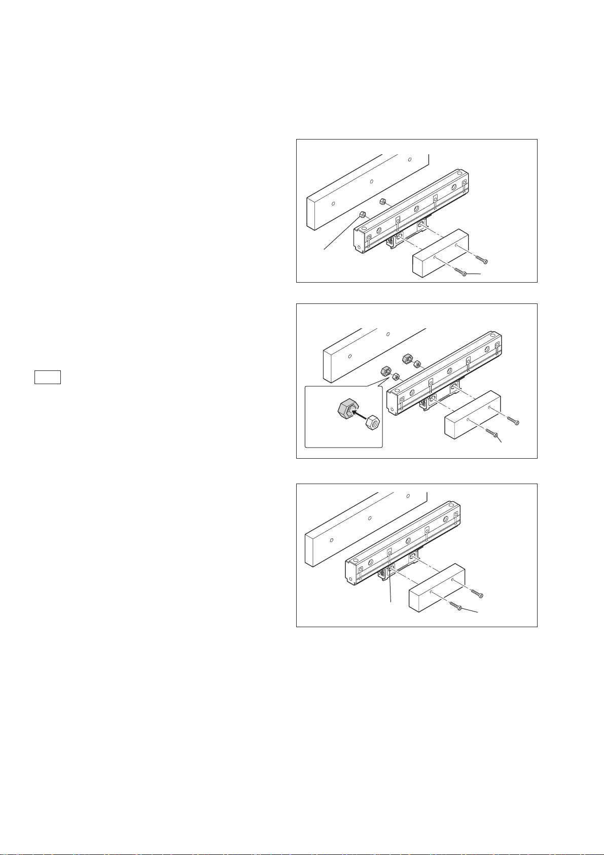
例 3:その他のスライダ取付方法
用途に合わせて取付けてください。
パターン 1
M4 の六角穴付ボルトは、お客様でご用意ください。
パターン 2
M4 ナットにゴムブッシュを取付けることにより、
ナットが脱落することなく取付けできます。
M4 の六角穴付ボルトは、お客様でご用意ください。
注意
ゴムブッシュによりナットの位置が制限されるため、
スライダ取付け穴の公差に気をつけてください。
パターン 3
M6 の六角穴付ボルトは、お客様でご用意ください。
M4
M4 ナット
(対辺8mm)
締付トルク
M4:2.7N·m
M4
ゴムブッシュ
M4 ナット
(対辺7mm)
締付トルク
M4:2.7N·m
締付トルク
M6:9N·m
M6
M6 タップ
■エアパージ
スケール両端のエンドカバー部には、標準でエアパージ用の M5 タップ穴があります。
詳細資料は別売の取扱説明書を参照してください。
Other manuals for SR87
1
This manual suits for next models
1
Table of contents
Languages:
Other Magnescale Scale manuals

Magnescale
Magnescale RS310-1800A User manual

Magnescale
Magnescale SL700 Series User manual

Magnescale
Magnescale BS78 User manual

Magnescale
Magnescale SmartSCALE SQ47-Z Series User manual

Magnescale
Magnescale SQ10 SERIES User manual

Magnescale
Magnescale PL25 User manual

Magnescale
Magnescale SJ300 Series Owner's manual

Magnescale
Magnescale SmartSCALE SQ57-Z Series User manual

Magnescale
Magnescale SJ300 SJ300 User manual

Magnescale
Magnescale SmartSCALE PQ10 Series User manual


