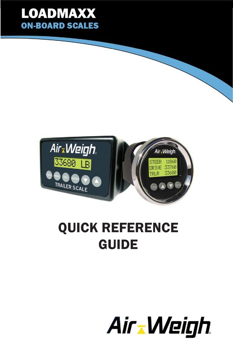
Air Weigh LoadMax User manual

LoadMaxx™On-Board Scales
TRACTOR SCALE SYSTEM
Self-Weighing Truck and Trailer Scales™
Calibration and
Operations Manual
for Tractors with a Hydraulic Lift
MODEL 5809
PN: 901-0121-000 R4

2
Table of Contents
LoadMaxx™ On-Board Scales.....................................................1
MODEL NUMBER NOTE ...............................................................5
I. LOADMAXX TRACTOR SCALE SYSTEM OVERVIEW...........5
I.A. Scale Display Overview ......................................................7
II. CALIBRATION ..........................................................................7
II.A. Preliminary Considerations ................................................8
II.B. CALIBRATING THE TRACTOR SCALE OVERVIEW .......9
II.D. MANUAL CALIBRATION PROCEDURE...........................9
II.D.1. CALIBRATING EMPTY WEIGHTS ..........................10
II.D.2. CALIBRATING HEAVY WEIGHTS...........................11
II.E. Calibration by Direct Entry of RATIO and OFFSET.........12
III. OPERATIONS ........................................................................12
IV. FUNCTIONAL OPERATIONS ...............................................12
IV.A. Weight Displays..............................................................12
IV.B. How-To-Weigh instructions.............................................13
IV.C. Creating a PIN................................................................14
IV.D. Alarm Function ...............................................................14
IV.D.1. Alarm Function Programming Procedure................15
IV.D.1.a. ALARM WEIGHTS...............................................15
IV.D.1.b. TURNING THE ALARM FEATURE ON OR OFF15
IV.D.2. Using Alarm 2 For Steer Axle Underweight ............16
IV.E. LANGUAGES .................................................................16
IV.F. DISPLAY BACKLIGHT AND SET-UP ............................16
IV.G. LARGE CHARACTER DISPLAY....................................17
V. QUICK REFERENCE MENU DIRECTORY............................18
VI. MENU OPERATIONS AND DEFINITIONS ...........................19
WEIGHTS DISPLAYS ..............................................................19
MAIN MENU.........................................................................19
WEIGHTS.............................................................................19

3
ALARMS...............................................................................19
PRINT, SETUP MENU.........................................................19
PRINT MENU.......................................................................19
SYSTEM SETUP MENU......................................................19
CALIBRATION .....................................................................19
SYS CONFIG .......................................................................19
SET PIN # ............................................................................19
SYS CONFIG MENU............................................................19
DISPLY SETUP....................................................................19
SCALE TYPE.......................................................................20
DISPLY SETUP MENU........................................................20
WEIGHT SETUP MENU ......................................................20
LBS / KGS............................................................................20
2 OR 3 LINES.......................................................................20
FILTER FREQ......................................................................20
SHOW / HIDE.......................................................................20
BACKLIGHT.........................................................................20
SCALE TYPE MENU............................................................20
MODEL NUMBER................................................................20
DATA/REPORT....................................................................20
MORE OPTIONS .................................................................21
CAN PROTOCOL.................................................................21
INCLINOMETR.....................................................................21
SHOW / HIDE MENU...........................................................21
SHOW GVW.........................................................................21
SHOW STEER.....................................................................21
SHOW HELP........................................................................21
SYSTM STATUS..................................................................21
DIAGNOSTICS: ALARM WEIGHTS MENU........................22
ALRM WEIGHTS..................................................................22

4
TEST ALARM.......................................................................22
DIAGNOSTICS: COMLINKS MENU...................................22
A/D READINGS....................................................................22
CALIB DATA ........................................................................22
COMLINK ID ........................................................................22
VII. SYSTEM TROUBLE SHOOTING.........................................23
VII.A. INCORRECT WEIGHT READINGS..............................24
VIII. MAINTENANCE...................................................................25
IX. CUSTOMER SUPPORT.........................................................25
X. Index of Application Notes...................................................26
Limited Warranty.........................................................................27
Procedure for Warranty Claims.................................................28

5
In the LoadMaxx Cab Display menus for the 5809 configuration,
the word “DRIVE” and its abbreviations, such as “DRV,” refer to
the hydraulic lift system, which is over the tractor drive axles.
Therefore this manual also occasionally refers to the hydraulic lift
as drive axles or axle group.
MODEL NUMBER NOTE
This guide is intended for use with the sensor configuration represented
by model number 5809.
Configuration
Lift
Trailer
5809
Hydraulic
Drop & Hook: Trailer weight
is available when a trailer
equipped with a calibrated
Air-Weigh scale is attached to
the tractor.
I. LOADMAXX TRACTOR SCALE SYSTEM OVERVIEW
The LoadMaxx on-board scale converts tractor and trailer suspension
loads or hydraulic lift load to an accurate on-ground weight. Once
calibrated correctly, as described in this manual, the scale will display
accurate weights for any load.
The scale will display the actual on-ground weight for the hydraulic lift axle
group to within 300 pounds (140 kgs), given a stable hydraulic system.
For the hydraulic lift, an axle group is defined as the set of axles
supporting the lift.
For any trailer air suspensions, an axle group is similarly defined by the
Height Control Valves (HCV), or leveling valves, on the air suspension.
For instance, a tandem drive axle suspension typically has only one HCV,
so the two drive axles are referred to as a single axle group and the
weight displayed will be for the total tandem weight.
The LoadMaxx scale display can show up to eight axle groups on one
tractor/trailer combination. Once the LoadMaxx is calibrated for weight, it

6
is not necessary to recalibrate unless the suspension characteristics
change. For details see “Troubleshooting”.
For best accuracy, calibrate and weigh on a level surface.
To calibrate or weigh the hydraulic lift, you must lift the front of
the trailer slightly to pressurize the hydraulic system. Briefly
release the PTO pressure to stabilize the hydraulic pressure.
Select an easily repeatable weighing position where the trailer
body is raised 6-12 inches.
If calibrating a trailer, release the trailer brakes, to release
suspension binding. Calibrating or observing spring or air
suspension weight readings with the brakes engaged will result
in inaccuracy.
Air-Weigh recommends that the suspension of a vehicle
equipped with air-suspension dump valves be momentarily
exhausted and re-inflated before calibrating or weighing. 5-10
seconds of air dump is normally sufficient. This will improve
repeatability and accuracy.
Any tractor equipped with a LoadMaxx Tractor Scale will automatically
display trailer weight data from Air-Weigh equipped trailers. No re-
calibration or trailer ID entry is required. No special tractor-trailer
connection is necessary, because the Air-Weigh Trailer Scale transmits
weight data over the vehicle’s existing 7-wire cord (J-560). This is a true
drop and hook application.

7
I.A. Scale Display Overview
Before using your Air-Weigh Tractor
Scale, it is necessary to calibrate it.
Before starting that process it’s a
good idea to become familiar with the
Scale Display.
Below is a definition of the use of
each button. The function and use of
these buttons remain the same
throughout all operations of the
scale.
I.B. Front Panel Buttons
1. When the Scale Display backlight is off, the first button push turns on the
backlight, with no other effect.
2. Depressing the ESC key (with the backlight lit) changes the Weights
Display to the Main Menu, depicted above. It changes all other menus
and displays to the previous screen. If you are entering a number,
depressing the ESC key clears the numeric entry without changing the
scale’s value.
3. The cursor location on the 5800 is indicated by the blinking line. In the
Scale Display images below, an orange highlight indicates the cursor
location.
4. To change the cursor location, or to set a numeric value, depress the up
or down arrow keys ▲ or ▼.
5. The instruction “Select [some menu item]” will appear frequently in the
text that follows. To select a menu item, depress the ENTER key after
setting the cursor to the specified line, that is, after making the specified
line start blinking.
6. To enter a numeric value, depress the ENTER key after setting the value
to the desired number.
II. CALIBRATION
There are two methods of calibrating the LoadMaxx Tractor Scale. The
usual method is by entering the EMPTY weights into the scale system
when the vehicle is empty, and entering the HEAVY weights into the scale
system when the vehicle is fully loaded. You can also calibrate Air-Weigh
Trailer Scales through the same menu sequence, by using the Tractor
Scale Display keypad.

8
When selecting this calibration method, you MUST enter empty weights
when the vehicle is empty and heavy weights when the vehicle is loaded
heavy. Failing to do so will result in inaccurate weight readings.
Alternatively, for those with hydraulic lift systems or suspensions on
several vehicles, it may be more convenient to enter the RATIO and
OFFSET calibration data directly, if these are known.
Use only one of these methods (the usual method, or alternatively, direct
ratio and offset entry) to calibrate the scale.
Once calibrated, if a lift or suspension weight is always incorrect by the
same amount on the empty and heavy weights, it is easy to adjust the
scale to correct it by using the ADJUST function.
II.A. Preliminary Considerations
The accuracy of the LoadMaxx Tractor Scale depends on the accuracy of
the certified scale used to calibrate or check-weigh. Ensure that the in-
ground scale is reliable, recently certified and in good repair. It is
preferable to obtain all weight tickets from the same certified scale. This
ensures comparative accuracy. Segmented scales, those that provide
individual axle group weights, are preferred. When segmented scales are
not available, take extra precaution in calculating weights.
For the best calibration results, the tractor and trailer should be:
Parked on level ground
Full tank of fuel
Tractor brakes released
Engine running
Front of the trailer raised slightly to pressurize the hydraulic
system.
Once the LoadMaxx Tractor Scale is calibrated, it is not necessary to re-
calibrate unless the suspension or hydraulic lift system characteristics
change.
Assigning a PIN number during the system set-up process will protect the
calibration procedure from tampering. Normally a PIN number is not
assigned until AFTER the scale has been calibrated. Air-Weigh Trailer
Scales also have a PIN lock-out to prevent tampering when the trailer is
parked, however any Air-Weigh equipped tractor will still have access to
the Trailer Scale’s calibration function through the in-cab truck scale. See
Section IV.B for PIN information.

9
II.B. CALIBRATING THE TRACTOR SCALE OVERVIEW
For Manual Calibration, the EMPTY and HEAVY axle weights must be
entered by the user. When calibrating using this method, the EMPTY
weights must be entered while the vehicle is empty, and the HEAVY
weights must be entered while the vehicle is fully loaded. Failure to
calibrate scales when vehicle is actually empty and when it has a true
heavy load will result in inaccurate weights.
Air-Weigh recommends that both empty and full weights be taken on the
same reliable, certified scale, preferably a segmented scale that will
provide axle weights.
The order of calibration is not important; however, both EMPTY and
HEAVY weights must be properly entered before the weight display is
accurate. Once the calibration procedure is properly completed one time,
the EMPTY or HEAVY weights can be updated or re-calibrated
individually.
Visit our YouTube channel to view our online installation and
calibration videos: http://www.youtube.com/user/AirWeigh
II.D. MANUAL CALIBRATION PROCEDURE
Remember, EMPTY or HEAVY weight calibrations can be entered in
any order, but the HEAVY weights must be entered while the trailer
is loaded, and the EMPTY weights must be entered while the trailer
is EMPTY. Additionally, the scale must have both EMPTY and
HEAVY weights entered before calibration is complete and accurate
weights are displayed.
The following two pages give step-by-step procedures for entering the
EMPTY and HEAVY calibrations, respectively.

10
II.D.1. CALIBRATING EMPTY WEIGHTS
1. Press <ESC> one or more times until the Main Menu appears, with VIEW
WEIGHTS blinking.
2. Select PRINT,SETUP, leading to next menu.
3. Select SYSTEM SETUP, leading to next menu.
4. Select CALIBRATION, leading to next menu.
5. Select MANUAL CALIBRATION, leading to next menu.
6. Select EMPTY WEIGHT, leading to next menu.
7. The screen pauses for three seconds with the display, “ENTER EMPTY –
VEHICLE MUST BE EMPTY” before proceeding automatically to the next
menu.
8. On the PICK AXL menu, select one of the offered axle groups: STR
(Steer), DRV (Drive), TRL (if only one trailer) or TRA (Trailer A if more
than one trailer) and TB (Trailer B). The display may also allow choice
from C (Trailer C) up to G (Trailer G). Select DRV for the hydraulic lift.
If PIN is needed for access, enter it at this time.
(See Section IV.C for PIN setup instructions)
9. Using the up/down arrows <>, scroll to the proper empty weight
identified from a certified scale ticket, then depress <ENTER>. The
screen will briefly show Accepted to indicate its acceptance of the Empty
Weight.
10. If one or more trailers are attached, repeat the above steps for the for the
trailer(s). Press <ESC> to return to the PICK AXL menu and choose
another axle for entering its Empty Weight calibration.
11. Some older tractor and trailer software versions will not allow trailer weight
calibration through the tractor scale if the trailer scale has a PIN#.
These must be programmed through the trailer scale or the PIN
temporarily disabled to allow access through the tractor scale.

11
II.D.2. CALIBRATING HEAVY WEIGHTS
1. Press <ESC> one or more times until the Main Menu appears, with VIEW
WEIGHTS blinking.
2. Select PRINT,SETUP, leading to next menu.
3. Select SYSTEM SETUP, leading to next menu.
4. Select CALIBRATION, leading to next menu.
5. Select MANUAL CALIBRATION, leading to next menu.
6. Select HEAVY WEIGHT, leading to next menu.
7. The screen pauses for three seconds with the display, “ENTER HEAVY –
VEHICLE MUST BE HEAVY” before proceeding automatically to the next
menu.
8. On the PICK AXL menu, select one of the offered axle groups: STR
(Steer), DRV (Drive), TRL (if only one trailer) or TRA (Trailer A if more
than one trailer) and TB (Trailer B). The display may also allow choice
from C (Trailer C) up to G (Trailer G). Select DRV for the hydraulic lift.
If PIN is needed for access, enter it at this time.
(See Section IV.C for PIN setup instructions)
9. Using the up/down arrows <>, scroll to the proper empty weight
identified from a certified scale ticket, then depress <ENTER>. The
screen will briefly show Accepted to indicate its acceptance of the Heavy
Weight.
10. If one or more trailers are attached, repeat the above steps for the for the
trailer(s). Press <ESC> to return to the PICK AXL menu and choose
another axle for entering its Heavy Weight calibration.
11. Some older tractor and trailer software versions will not allow trailer weight
calibration through the tractor scale if the trailer scale has a PIN#.
These must be programmed through the trailer scale or the PIN
temporarily disabled to allow access through the tractor scale.

12
II.E. Calibration by Direct Entry of RATIO and OFFSET
To use this method, you must first obtain the RATIO and OFFSET values
from another LoadMaxx Tractor Scale on a tractor with an identical
hydraulic lift system, which already has been correctly calibrated. Then
you can directly enter these values into the Tractor Scale you wish to
calibrate.
For further details, refer to Product Application Note Calibration by Direct
Entry of RATIO and OFFSET Values, Air-Weigh P/N 903-0115-000.
III. OPERATIONS
Once calibrated, your Air-Weigh LoadMaxx Tractor Scale is ready to
display weights in 20lb (20kg) increments, and be accurate to within
300lbs (140kgs) of a certified ground scale. Continued accuracy is
established by following a few simple rules before taking weight readings:
1. Park the tractor and trailer on a level surface.
2. If equipped with a trailer scale and a trailer dump valve, release trailer
brakes. Dump air in trailer suspension for 5 –10 seconds, then re-inflate
to factory-specified ride height.
3. Accurate weight is displayed when numbers stop blinking.
It may take a few loads to learn how to weigh accurately, but with a little
practice you should be able to weigh within 100 lbs. on a regular basis.
With Air-Weigh scales installed on the tractor and trailer suspensions,
your entire vehicle becomes the scale. When you want to weigh,
remember that you need to weigh the vehicle the same way every time.
IV. FUNCTIONAL OPERATIONS
IV.A. Weight Displays
The Weight Displays show the weights for all axle
groups, the GVW (Gross Vehicle Weight), and the
NET (Net Vehicle Payload). You can reach the DRIVE
Weight Display by depressing the <ESC> button
repeatedly until it appears, or alternatively by selecting
VIEW WEIGHTS on the Main Menu and depressing the
<ENTER> button.
Use the up/down arrows <> to scroll between the
various weight displays showing tractor, trailer, and
GVW/NET weights.

13
On all Weight Displays, when a weight is changing, it flashes rapidly until
it stabilizes.
On all Weight Displays, if a particular axle (or GVW or
Net) is over the alarm or warning weight, causing an
alarm, a bell icon flashes rapidly between the axle
name (or GVW or Net) and its weight.
On all Weight Displays, pushing Enter stops the alarm
unless PIN protection is active. See “Alarm Function,”
above, for full details.
If no alarm is active, you can zero the NET on the GVW screen by
pressing <ENTER> twice while that screen is displayed. The first time,
the Net Weight flashes slowly. The second time, it goes to zero. The
amount of each addition to, or subtraction from, the GVW will then be
added to or subtracted from the Net Weight, allowing you to see how
much weight has been loaded or unloaded.
IV.B. How-To-Weigh instructions
How-To-Weigh instructions are displayed on the tractor scale in rotation
with the actual weight screen. To turn off these instructions permanently:
1. Press <ESC> one or more times until the Main Menu
appears, with VIEW WEIGHTS blinking.
2. Select PRINT,SETUP, leading to the next menu.
3. Select SYSTEM SETUP, leading to the next menu.
4. Select SYS CONFIG, leading to the next menu.
5. Select DISPLY SETUP, leading to the next menu.
6. Select SHOW / HIDE, leading to the next menu.
7. Select SHOW HELP, leading to the next menu.
8. Select HIDE HELP to turn off the How-To-Weigh
instructions. Press <ESC> repeatedly to return to the
main menu.

14
Note: You can turn off the How-To-Weigh instructions temporarily,
until the next time you turn the truck off and on, by pushing either of
the up/down arrows <
> when the instructions are visible.
IV.C. Creating a PIN
When the trailer scale PIN is set to 0, the operator will not need to enter a
PIN to access the PROGRAM menu functions. Setting a PIN into the
LoadMaxx Tractor Scale will eliminate tampering with that scale’s
CALIBRATION, SCALE TYPE, and PIN settings. After calibration, fleets
with both tractor and trailer scales should develop a fleet PIN policy to
protect the calibration settings from tampering.
To set a PIN:
1. Select PRINT,SETUP, leading to the next menu.
2. Select SYSTEM SETUP, leading to the next menu.
3. Select SYS CONFIG, leading to the next menu.
4. Select SET PIN #, leading to the next menu.
If PIN is needed for access, enter it at this time.
5. Using the up/down arrows <> scroll to the desired PIN, then
depress <ENTER>. Press <ESC> repeatedly to return to main
menu.
The new PIN is now entered into the scale. To change the PIN later,
repeat these steps and change the setting. Setting the PIN to zero will
reset the scale’s PIN to its original status of No PIN Needed.
Note that once you gain PIN access by entering the PIN correctly, you will
retain that access until the scale has a power cycle.
IV.D. Alarm Function
The Air-Weigh LoadMaxx Tractor Scale has two 12V-24V 1.0 amp output
alarms. To use the alarm feature, attach the gray or brown alarm output
wire stemming from the Tractor ComLink harness to a user-supplied
alarm. Wires are marked WARN 1 and WARN 2. Route the ground wire/s
for the alarm/s to the WARN GROUND wire/s at the Tractor ComLink
harness. Alarms will activate when a programmed warning weight or
alarm weight limit is reached. The limits activating this feature are set by
the user. The user may also select Alarm 2 to activate when the STEER
weight is less than 20% of the GVW.
Warning weight output is pulsing voltage, while alarm weight output is
continuous voltage.
You can delay the period between each overweight and the subsequent
activation of the alarm, by up to sixty seconds. Similarly, you can delay
the period between the return to not overweight, and the alarm’s

15
deactivation, by up to sixty seconds. These delays can prove useful in
moderating alarm responses to weight oscillations, such as those
occurring during travel. For details, see Product Application Note
Installing and Programming Overweight Alarms, P/N 903-0122-000.
To deactivate and reset an active warning or alarm weight alarm, simply
press the Enter button <ENTER> once while one of the weight displays
for tractor, trailer or GVW/NET screen is displayed on the scale display
screen. If the scale is not PIN-protected, this will stop power from flowing
to the alarm output wire. Once the displayed weight readings fall below
the programmed alarm settings, the alarm function resets. The alarm
feature is now ready for the next load.
IV.D.1. Alarm Function Programming Procedure
IV.D.1.a. ALARM WEIGHTS
1. Press <ESC> one or more times until the Main Menu appears, with
VIEW WEIGHTS blinking.
2. Select ALARMS, leading to the next menu.
If PIN is needed for access, enter it at this time.
(See Section IV.C for PIN setup instructions)
3. Select SET ALARMS, leading to the next menu.
4. Select ALARM 1, leading to the next menu.
5. Select one of GVW, NET ALM 1, TRCTR ALRMS1, or TRLER
ALRMS1, leading to the next menu.
6. Depending on the previous step,
select from GVW ALARM and NET ALARM;
or from STEER ALARM and DRIVE ALARM;
or from TRLR WARN 1 and TRLR ALARM 1. (If there are
multiple trailers, it will be necessary to select from TRAILER A,
TRAILER B, TRAILER C, etc.)
7. Select WARN WT 1 or ALARM WT 1 for the chosen alarm.
8. Using the up/down arrows <> scroll to the desired warning or
alarm weight, then depress <ENTER>.
9. Press <ESC> as needed to start setting any additional desired
alarms. Press <ESC> repeatedly to return to previous menu or the
main menu. Repeat this procedure for ALARM 2 if used.
IV.D.1.b. TURNING THE ALARM FEATURE ON OR OFF
1. Press <ESC> one or more times until the Main Menu appears, with
VIEW WEIGHTS blinking.
2. Select ALARMS, leading to the next menu.
If PIN is needed for access, enter it at this time.

16
(See Section IV.C for PIN setup instructions)
3. The bottom line gives the state of the alarm feature, “(Now ON)” or
“(Now OFF).” Select TURN ON/OFF to change this state to its
opposite.
NOTE: Remember, to deactivate and reset an active warning or
alarm weight, simply press the Enter button <ENTER> once
while alarms are active, while weights are being displayed. To
turn the alarm function completely off, go back to the TURN
ON/OFF portion of the ALARMS menu and change the (Now ON)
back to a (Now OFF).
IV.D.2. Using Alarm 2 For Steer Axle Underweight
You can change the function of Alarm 2 from its default use as a second
overweight alarm. Instead, you can use it to activate when the on-the-
ground weight at the steer axle tires is less than 25% of the on-the-ground
weight at the drive axle tires. However, this function is not used on
hydraulic lift systems, because they do not measure steer axle weight.
IV.E. LANGUAGES
The LoadMaxx offers a choice of language display:
1. Press <ESC> one or more times until the Main Menu appears, with
VIEW WEIGHTS blinking.
2. Select PRINT,SETUP, leading to the next menu.
3. Select SYSTEM SETUP, leading to the next menu.
4. Select SYS CONFIG, leading to the next menu.
5. Select LANGUAGE, , leading to the next menu.
6. Press the <> buttons to select the desired language, then
depress <ENTER>.
IV.F. DISPLAY BACKLIGHT AND SET-UP
Like other gauges, the scale display is “key-on” powered, so it is always
operating. Pressing any key will automatically turn on the display
backlight. The display screen will automatically drop into its programmed
“sleep mode” with the backlight turned off after one to 30-minutes from the
last keystroke operation. The factory-set default time is 5 minutes.
To change the amount of time the display is lit
1. Press <ESC> one or more times until the Main Menu appears, with
VIEW WEIGHTS blinking.
2. Select PRINT,SETUP, leading to the next menu.
3. Select SYSTEM SETUP, leading to the next menu.
4. Select SYS CONFIG, leading to the next menu.
5. Select DISPLY SETUP, leading to the next menu.
6. Select BACKLIGHT, leading to the next menu.

17
7. Press the <> buttons to select the desired time period. Press
ENTER.
This backlight will automatically dim to the “sleep mode” after the selected
operation time period. To turn on the backlight, press any button.
IV.G. LARGE CHARACTER DISPLAY
The Air-Weigh LoadMaxx Tractor
Scale can display weights on either
three lines, with twelve characters per
line as shown here on the left, or with
larger characters, on two lines, with
eight characters per line, as shown
here on the right.
Only the Weights Displays can appear as large characters on two lines.
On this display, axle group names are represented by their first letters:
S = STEER
D = DRIVE
G = Gross Vehicle Weight (GVW)
N = Net Payload (NET)
T = TRAILER (if one semi trailer, or
full trailer)
A = TRAILER A (if two trailers)
B = TRAILER B (if two trailers)
F = FRONT TRAILER (full trailer)
R = REAR TRAILER (full trailer)
All other screens always appear as three line displays.
To change between two line and three line displays:
1. Press <ESC> one or more times until the Main Menu appears, with
VIEW WEIGHTS blinking.
2. Select PRINT,SETUP, leading to the next menu.
3. Select SYSTEM SETUP, leading to the next menu.
4. Select SYS CONFIG, leading to the next menu.
5. Select DISPLY SETUP, leading to the next menu.
6. Select WEIGHT SETUP, leading to the next menu.
7. Select 2 OR 3 LINES, leading to the next menu. At the bottom of the
menu the current choice is shown as (Now 2 LINE) or (Now 3 LINE).
At this point you can choose between the two line display with larger
characters, or the three line display.
8. Press the <> buttons to select the desired display configuration, 2
LINE DISP or 3 LINE DISP, and press <ENTER>.

18
V. QUICK REFERENCE MENU DIRECTORY
LoadMaxx Scale System
CALIBRATION REQUIRED
BEFORE USE
WEIGHTS
ALARMS
PRINT, SETUP
(shows only SETUP if data stream)
PRINT MENU (if no data stream)
SYSTEM SETUP
CALIBRATION
SYS CONFIG
SET PIN#
DIAGNOSTICS
WEIGHT
Displays first 3 axle weights
(Next axle weights if any)
<> for GVW/Net Payload
Or
TRAILER NET PAYLOAD
(Models 5858, 5859 only)
ALARMS
SET ALARMS (Requires PIN#.)
ALARM 1 (or ALARM 2 if not using
STR 20% GVW)
GVW, NET ALM1 (or ALM 2)
GVW ALARM
WARN WT 1 (or 2)
ALRM WT 1
NET ALARM
WARN WT 1
ALRM WT 1
TRCTR ALRMS1
STEER ALARM
WARN WT 1
ALRM WT 1
DRIVE ALARM
WARN WT 1
ALRM WT 1
TRLER ALRMS1
WARN WT 1
ALRM WT 1
ALARM CNTROLS
STR 20% GVW
ALARM LOGIC
ALARM DELAYS
TURN ON/OFF
PRINT, SETUP
(shows only SETUP if data stream)
PRINT MENU (if no data stream)
PRINT REPORT
DATE / TIME
REPRT COPIES
SYSTEM SETUP
CALIBRATION (Requires PIN#.
Each axle suspension must be calibrated
separately.) ADJUST CALIB
MANUAL CALIB
EMPTY WEIGHT
HEAVY WEIGHT
ENTER RATIO
CALIB RATIO
CALIB OFFSET
SYS CONFIG
DISPLAY SETUP
WEIGHT SETUP
LBS/KGS
2 OR 3 LINES
FILTER FREQ
SHOW/HIDE
SHOW GVW
SHOW STEER
SHOW HELP
BACKLIGHT
SCALE TYPE (Requires PIN#)
MODEL NUMBER
(Changes sensor configuration.)
DATA/REPORT
MORE OPTIONS
CAN PROTOCOL
INCLINOMETR
LANGUAGE
SET PIN #
DIAGNOSTICS
SYSTEM STATUS
ALARMS
ALARM WEIGHTS
TEST ALARM (TRACTOR)
COMLINKS
A/D READINGS
CALIB DATA
USER DATA<A/D>
USER DATA<WEIGHTS>
COMLINK ID

19
VI. MENU OPERATIONS AND DEFINITIONS
Press the <ESC> button one or more times to reach the Main Menu. Use
the <> and <> buttons to scroll to new selections. Refer to the Quick
Reference Menu Directory above for the entire menu structure.
WEIGHTS DISPLAYS
See Section IV.A.
MAIN MENU
Press <ESC> to enter the Main Menu from the Weights Display. From all
other displays, press <ESC> one or more times to reach the Main Menu.
WEIGHTS
Press <ENTER> to observe the first weights screen, showing at least the
DRIVE axle weight, and possibly the TRLR weight. Press the <> to
scroll to additional weight screens for trailer, GVW, and Net Payload
weights.
ALARMS
See Section IV.D.
PRINT, SETUP MENU
PRINT MENU
Print a report or set the printer’s date and time. See Product Application
Note Air-Weigh Date Time Printer Installation Instructions, P/N 901-0105-
000 (Rev 2), available at
http://www.air-weighscales.com/support/manuals.cfm, for details. In
addition, select REPRT COPIES to set the number of report copies.
SYSTEM SETUP MENU
CALIBRATION
See Section II.
SYS CONFIG
See the SYS CONFIG MENU subsection, below.
SET PIN #
See Section IV.C.
SYS CONFIG MENU
DISPLY SETUP
See the DISPLY SETUP MENU subsection, below.

20
SCALE TYPE
See the SCALE TYPE MENU subsection, below.
DISPLY SETUP MENU
WEIGHT SETUP MENU
LBS / KGS
Changes the weight display and data entry modes to pounds or
kilograms. Changing this selection will also automatically convert any
calibration values previously entered to the new unit of measure.
2 OR 3 LINES
Causes the Weight Displays to appear in large or normal characters. See
Section IV.G.
FILTER FREQ
Allows filtering out weight measurement spikes and oscillations. Refer to
Product Application Note Filtering Out Weight Spikes, P/N 903-0135-000,
for more information on this subject.
SHOW / HIDE
See the SHOW / HIDE subsection, below.
BACKLIGHT
Changes the amount of time the display is backlit from last keystroke.
Factory default is 5 minutes. Duration can be selected from one to 30
minutes.
SCALE TYPE MENU
MODEL NUMBER
Used to change the LoadMaxx Truck Scale configuration; for instance,
when adding an additional sensor at a later date. This Guide is intended
only for Model 5809. Consult Air-Weigh Customer Support before
changing MODEL NUMBER.
DATA/REPORT
Changes the printer port configuration. WEIGHT TICKT configures the
printer port to print Weight Ticket reports. DATA STREAM and OBM
STREAM (On Board Mass stream) configure the port to output vehicle
weights to another electronics device, approximately twice per second.
For DATA STREAM, refer to Product Application Note LoadMaxx Weights
Output Data Stream on its RS232 Port, P/N 903-0084-000. For OBM
STREAM, refer to Product Application Note LoadMaxx On Board Mass
Output Data Stream on its RS232 Port, P/N 903-0143-000. Consult Air-
Weigh Support for more information on this subject.
This manual suits for next models
1
Table of contents
Other Air Weigh Scale manuals

Air Weigh
Air Weigh LoadMaxx 5809 User manual

Air Weigh
Air Weigh BinMaxx User manual

Air Weigh
Air Weigh LOADMAXX User manual

Air Weigh
Air Weigh LOADMAXX User manual

Air Weigh
Air Weigh QuickLoad User manual

Air Weigh
Air Weigh BinMaxx User manual

Air Weigh
Air Weigh LoadMaxx Plus User manual

Air Weigh
Air Weigh LOADMAXX Operating and maintenance instructions

Air Weigh
Air Weigh BinMaxx User manual