Shinko JIR-301-M Use and care manual
1
11 YA(-)
14 YB(+)
17 SG
11 YA(-)
14 YB(+)
17 SG
11 YA(-)
14 YB(+)
17 SG
4
3
1
6
JIR-301-M (Max 31 units)
To the JIR-301-M via CDM
COMMUNICATION INSTRUCTION MANUAL JIR-301-M (C5)No.JIR3CE4 2014.01
To prevent accidents arising from the misuse of this indicator, please ensure the operator receives this manual.
Warning
Turn the power supply to the instrument off before wiring or checking.
Working on or touching the terminal with the power switched on may result in severe injury or
death due to electric shock.
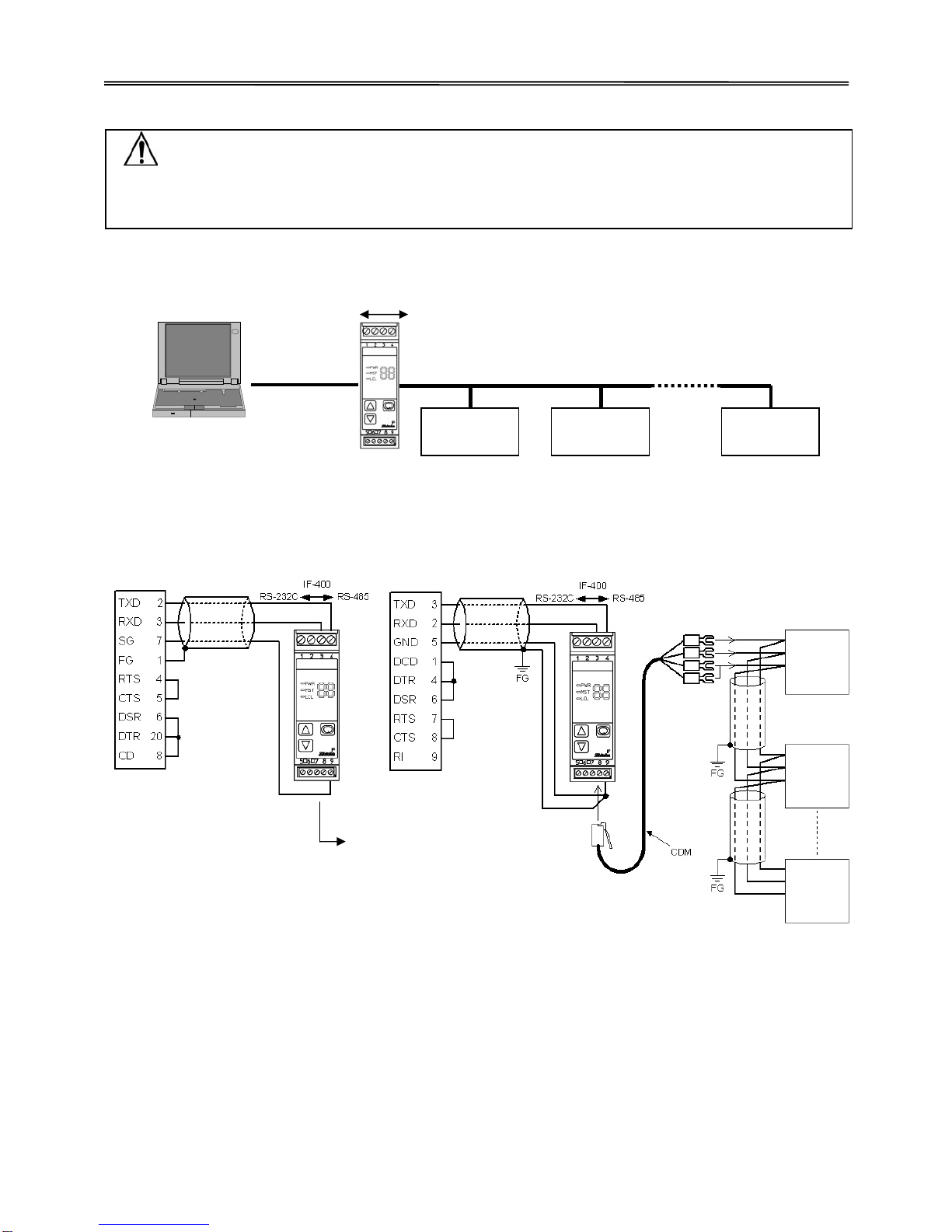
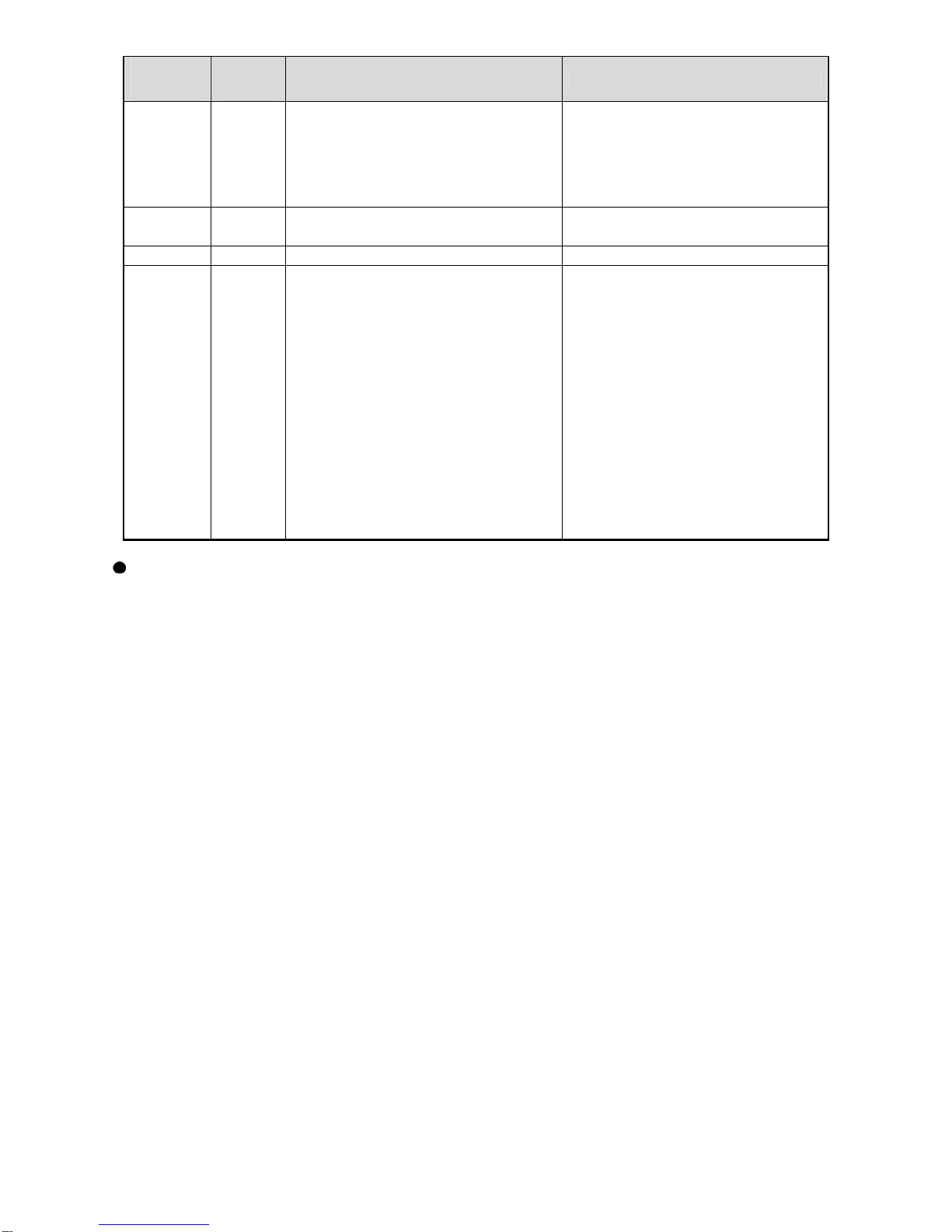
1. System Configuration
(Fig. 1-1)
2. Wiring
When using communication converter IF-400
•D-sub 25-pin connector •D-sub 9-pin connector
(Fig. 2-1)
Shielded wire
Connect only one end of the shielded wire to the FG terminal so that current cannot flow to the shielded
wire. If both ends of the shielded wire are connected to the FG terminal, the circuit will be closed
between the shielded wire and the ground. As a result, current will run through the shielded wire and
this may cause noise.
Be sure to ground FG terminal.
Recommended cable: OTSC-VB 2PX0.5SQ (made by Onamba Co., Ltd.) or equivalent
(Use a twisted pair cable.)
Terminator (Terminal resistor)
Communication converter IF-400 (sold separately) has a built-in terminator.
The terminator is mounted at the end of the wire when connecting a personal computer with multiple
peripheral devices. The terminator prevents signal reflection and disturbance.
Do not connect the terminator to the communication line because each JIR-301-M has built-in pull-up
and pull-down resistors instead of a terminator.
D-sub25-pin connector
Communication converter IF-400
RS-232C RS-485
JIR-301-M (Max 31 units)
JIR-301-M
No.0
JIR-301-M
No.1
JIR-301-M
No.30
Host computer
D-sub9-pin connector
Shielded wire
Shielded
wire
Host computer Host computer
Shielded wire
Shielded wire

2
3. Communication Parameters Setting
Set Communication parameters using front keypad. (Refer to the Instruction manual for each indicator.)
(1) Communication protocol
Select a communication protocol. (Default: Shinko protocol)
(2) Instrument number
Set an instrument number to each of the JIR-301-M units individually when communicating by
connecting multiple units. (Default: 0)
(3) Communication speed
Select a communication speed equal to that of the host computer. (Default: 9600 bps)
(4) Parity (Only Modbus protocol)
Select the parity. (Default: Even parity)
(5) Stop bit (Only Modbus protocol)
Select the stop bit. (Default: 1)
4. Communication Procedure
Communication starts with command transmission from the host computer (hereafter Master) and
ends with the response of the JIR-301-M (hereafter Slave).
• Response with data
When the master sends the reading command, the slave
responds with the corresponding set value or current status.
• Acknowledgement
When the master sends the setting command, the slave
responds by sending acknowledgement after the
processing is terminated.
• Negative acknowledgement
When the master sends a non-existent command or value
out of the setting range, the slave returns a negative
acknowledgement.
• No response
The slave will not respond to the master in the following cases:
• Global address (Shinko protocol) is set.
• Broadcast address (Modbus protocol) is set.
• Communication error (framing error, parity error)
• Checksum error (Shinko protocol), LRC discrepancy (Modbus
(Fig.4-1) ASCII mode), CRC-16 discrepancy (Modbus RTU mode)
Communication timing of the RS-485 (C5 option)
Master side (Take note while programming)
Set the program so that the master can disconnect the transmitter from the communication line within a
1 character transmission period after sending the command in preparation for reception of the response
from the slave.
To avoid the collision of transmissions between the master and the slave, send the next command after
carefully checking that the master has received the response.
If a response to the command is not returned due to communication errors, set the Retry Processing
to send the command again. (Retry twice or more is recommended.)
Slave side
When the slave starts transmission through the RS-485 communication line, the slave is arranged so as
to provide an idle status (mark status) transmission period of 1 or more characters before sending the
response to ensure synchronization on the receiving side.
The slave is arranged so as to disconnect the transmitter from the communication line within a 1 character
transmission period after sending the response.
5. Shinko Protocol
5.1 Transmission Mode
Shinko protocol is composed of ASCII codes.
Hexadecimal (0 to 9,A to F), which is divided into high order (4-bit) and low order (4-bit) out of 8-bit
binary data in command is transmitted as ASCII characters.
Data format Start bit: 1 bit
Data bit: 7 bits
Parity: Even
Stop bit: 1 bit
Error detection: Checksum
Command
Data
Command
Acknowledgement
Command
Negative
acknowledgement
Command
No response
Master Slave

3
5.2 Command Configuration
All commands are composed of ASCII.
The data (set value, decimal number) is represented by hexadecimal numbers.
The negative numbers are represented in 2's complement.
Numerals written below the command represent number of characters.
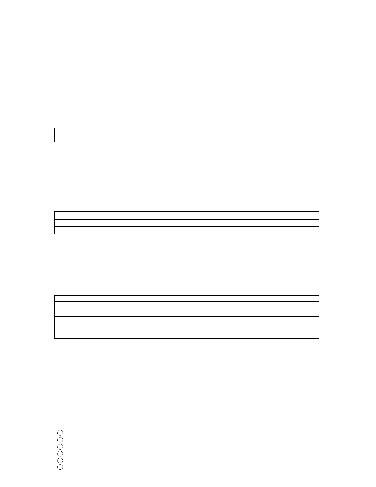
(1) Setting command
Header
(02H) Address Sub
address
(20H) Command
type (50H) Data
item Data Checksum Delimiter
(03H)
1 1 1 1 4 4 2 1
(2) Reading command
Header
(02H) Address Sub
address
(20H) Command
type (20H) Data
item Checksum Delimiter
(03H)
1 1 1 1 4 2 1
(3) Response with data
Header
(06H) Address Sub
address
(20H) Command
type (20H) Data
item Data Checksum Delimiter
(03H)
1 1 1 1 4 4 2 1
(4) Acknowledgement
Header
(06H) Address Checksum Delimiter
(03H)
1 1 2 1
(5) Negative acknowledgement
Header
(15H) Address Error
code Checksum Delimiter
(03H)
1 1 1 2 1
Header: Control code to represent the beginning of the command or the response.
ASCII codes are used.
Setting command, Reading command: STX (02H) fixed
Response with data,Acknowledgement: ACK (06H) fixed
Negative acknowledgement: NAK (15H) fixed
Instrument number (Address): Numbers by which the master discerns each slave.
Instrument number 0 to 94 and Global address 95.
ASCII codes (20H to 7FH) are used by adding 20H to instrument numbers 0 to 95
(00H to 5FH).
95 (7FH) is called the Global address, which is used when the same command is sent
to all the slaves connected. However, a response is not returned.
Sub address: 20H fixed
Command type: Code to discern Setting command (50H) and Reading command (20H)
Data item: Data classification of the command object.
Composed of hexadecimal 4 digits, usingASCII codes. (Refer to Section 7.)
Data: The contents of data (set value) differs depending on the setting command.
Composed of hexadecimal 4 digits, usingASCII codes. (Refer to Section 7.)
Checksum: 2-character data to detect communication errors. (Refer to “5.4 Checksum Calculation”.)
Delimiter: Control code to represent the end of command.ASCII codeETX (03H) fixed
Error code: Represents an error type withASCII codes. Composed of hexadecimal 1 digit.
1 (31H)-----Non-existent command
2 (32H)-----Not used
3 (33H)-----Setting outside the setting range
4 (34H)-----Status unable to be set (e.g.AT is performing)
5 (35H)-----During setting mode by keypad
5.3 Command Example
Numerals written below the command represent number of characters.
(1) Reading (Address 1, PV)
• Reading command from the master
Header
(02H)
Address
(21H)
Sub
address
(20H)
Command
type
(20H)
Data item
[0080H]
(30H 30H 38H 30H)
Checksum
(44H 37H)
Delimiter
(03H)
1 1 1 1 4 2 1
• A response from the slave in normal status [When PV=25 (0019H)]
Header
(06H)
Address
(21H)
Sub
address
(20H)
Command
type
(20H)
Data item
[0080H]
(30H 30H 38H 30H)
Data
[0019H]
(30H 30H 31H 39H)
Checksum
(30H 44H)
Delimiter
(03H)
1 1 1 1 4 4 2 1
4
(2) Reading (Address 1, A1)
• Reading command from the master
Header
(02H)
Address
(21H)
Sub
address
(20H)
Command
type
(20H)
Data item
[0001H]
(30H 30H 30H 31H)
Checksum
(44H 45H)
Delimiter
(03H)
1 1 1 1 4 2 1
• A response from the slave in normal status [WhenA1=600 (0258H)]
Header
(06H)
Address
(21H)
Sub
address
(20H)
Command
type
(20H)
Data item
[0001H]
(30H 30H 38H 30H)
Data
[0258H]
(30H 32H 35H 38H)
Checksum
(30H 46H)
Delimiter
(03H)
1 1 1 1 4 4 2 1
(3) Setting (Address 1, A1) [when setting A1 to 600 (0258H)]
• Setting command from the master
Header
(02H)
Address
(21H)
Sub
address
(20H)
Command
type
(50H)
Data item
[0001H]
(30H 30H 30H 31H)
Data
[0258H]
(30H 32H 35H 38H)
Checksum
(44H 46H)
Delimiter
(03H)
1 1 1 1 4 4 2 1
• A response from the slave in normal status
Header
(06H) Address
(21H) Checksum
(44H 46H) Delimiter
(03H)
1 1 2 1
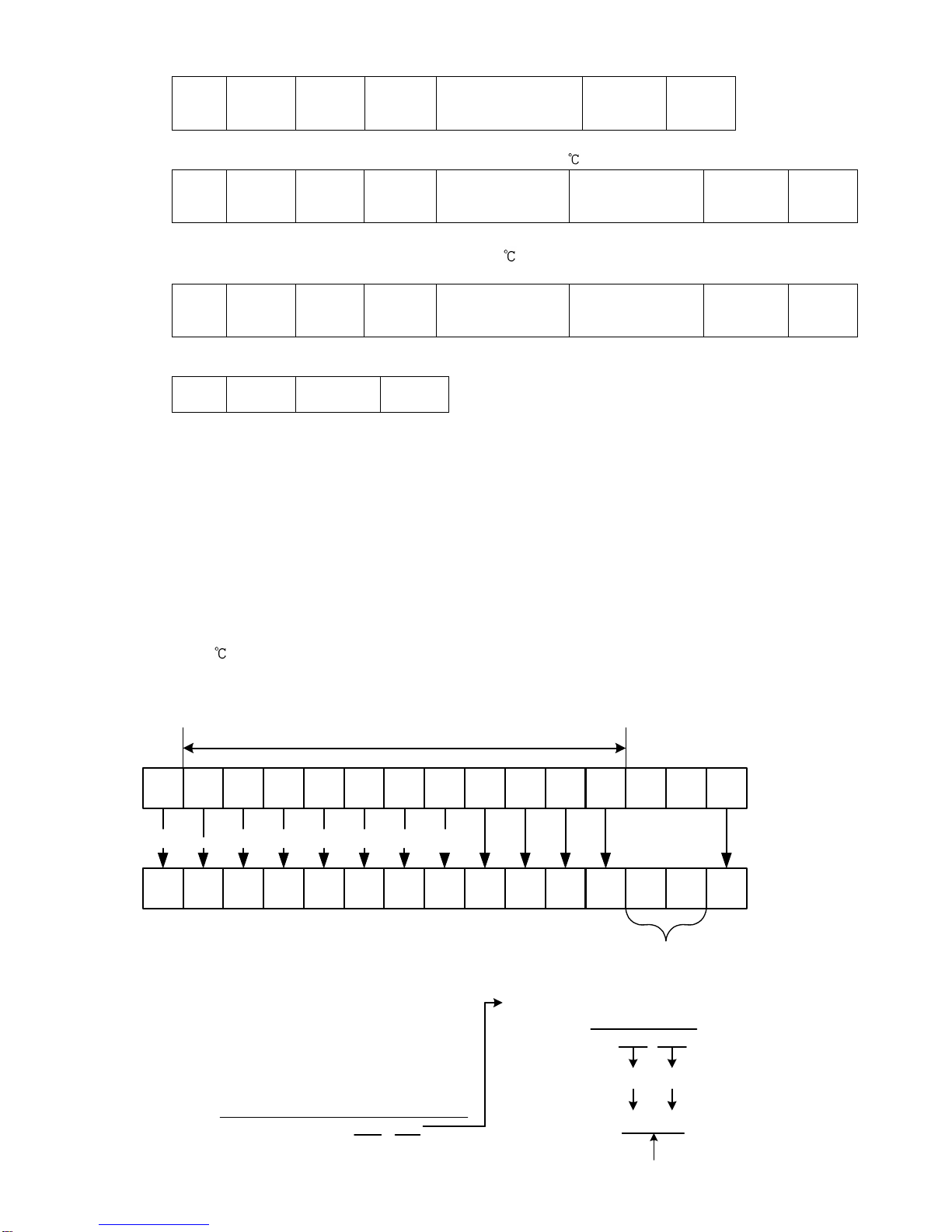
5.4 Checksum Calculation
Checksum is used to detect receiving errors in the command or data.
Set the program for the master side as well to calculate the checksum of the response data from the
slaves so that communication errors can be checked.
The ASCII code (hexadecimal) corresponding to the characters which range from the address
(instrument number) to that before the checksum is converted to binary notation, and the total value is
calculated.
The lower 2-digits of the total value are converted to 2’s complement, and then to hexadecimal figures,
that is, ASCII code for the checksum.
Checksum calculation example
A1: 600 (0258H)
Address (instrument number): 0 (20H)
• 1’s complement: Reverse each binary bit. 0 will become 1 and vice versa.
• 2’s complement:Add 1 to 1’s complement.
STX ETX
P 0 0 0 1 0 2 5 8
02H 20H 20H 50H 30H 30H 30H 31H 30H 32H 35H 38H 03H
[Characters above are represented in ASCII]
Checksum
Checksum calculation range
[e.g.]
E
45H 30H
0
20H
20H
50H
30H
30H
30H
31H
30H
32H
35H
38H
0010 0000
0010 0000
0101 0000
0011 0000
0011 0000
0011 0000
0011 0001
0011 0000
0011 0010
0011 0101
0011 1000
+10 0010 0000
[Hexadecimal] [Binary]
1101 1111
1
+1110 0000
E 0
45H 30H
[1's complement]
[2's complement]
[Hexadecimal]
[ASCII]
Checksum
5
6. Modbus Protocol
6.1 Transmission Mode
There are 2 transmission modes (ASCII and RTU) in Modbus protocol.
6.2 ASCII Mode
Hexadecimal (0 to 9,A to F), which is divided into high order (4-bit) and low order (4-bit) out of 8-bit
binary data in command is transmitted as ASCII characters.
Data format Start bit: 1 bit
Data bit: 7 bits
Parity: Even (Odd, No parity) Selectable
Stop bit: 1 bit (2 bits) Selectable
Error detection: LRC (Longitudinal Redundancy Check)
Data interval: 1 second or less (Max.1 second of interval between characters)
(1) Message configuration
ASCII mode message is configured to start by Header [: (colon)(3AH)] and end by Delimiter [CR
(carriage return) (0DH) + LF (Line feed)(0AH)].
Header
(:) Slave
address Function
code Data Error check
LRC Delimiter
(CR) Delimiter
(LF)
Slave address
Slave address is an individual instrument number on the slave side and is set within the range 0 to 95
(00H to 5FH).
The master identifies slaves by the slave address of the requested message.
The slave informs the master which slave is responding to the master by placing its own address in the
response message.
Slaveaddress0 (00H,broadcastaddress)canidentifyalltheslavesconnected.Howeverslavesdo notrespond.
Function code
The function code is the command code for the slave to undertake the following action types.
Function code Contents
03 (03H) Reading the set value and information from slaves
06 (06H) Setting to slaves
Function code is used to discern whether the response is normal (acknowledgement) or if any error
(negative acknowledgement) has occurred when the slave returns the response message to the master.
When acknowledgement is returned, the slave simply returns the original function code.
Whennegative acknowledgement is returned, the MSB of the original function code is set as 1 for the response.
For example, when the master sends request message setting 10H to the function code by mistake,
slave returns 90H by setting the MSB to 1, because the former is an illegal function.
For negative acknowledgement, the exception codes below are set to the data of the response message,
and returned to the master in order to inform it of what kind of error has occurred.
Exception code Contents
1 (01H) Illegal function (Non-existent function)
2 (02H) Illegal data address (Non-existent data address)
3 (03H) Illegal data value (Value out of the setting range)
17 (11H) Shinko protocol error code 4 (Status unable to be set, e.g.AT is performing)
18 (12H) Shinko protocol error code 5 (During setting mode by keypad operation)
Data
Data differs depending on the function code.
A request message from the master is composed of data item, amount of data and setting data.
A response message from the slave is composed of the number of bytes, data and exception codes in
negative acknowledgements. The amount of data to be dealt with in one message is “1”.
Therefore the amount of data is fixed as (30H)(30H)(30H)(31H).
Effective range of data is -32768 to 32767 (8000H to 7FFFH).
Error check: 2-character data to detect communication errors. Refer to “(2) Error check of ASCII mode”.
(2) Error check of ASCII mode
After calculating LRC (Longitudinal Redundancy Check) from the slave address to the end of data, the
calculated 8-bit data is converted to twoASCII characters and are appended to the end of message.
How to calculate LRC
1Create a message in RTU mode.
2Add all the values from the slave address to the end of data. This is assumed as X.
3Make a complement for X (bit reverse). This is assumed as X.
4Add a value of 1 to X. This is assumed as X.
5Set X as an LRC to the end of the message.
6Convert the whole message toASCII characters.

6
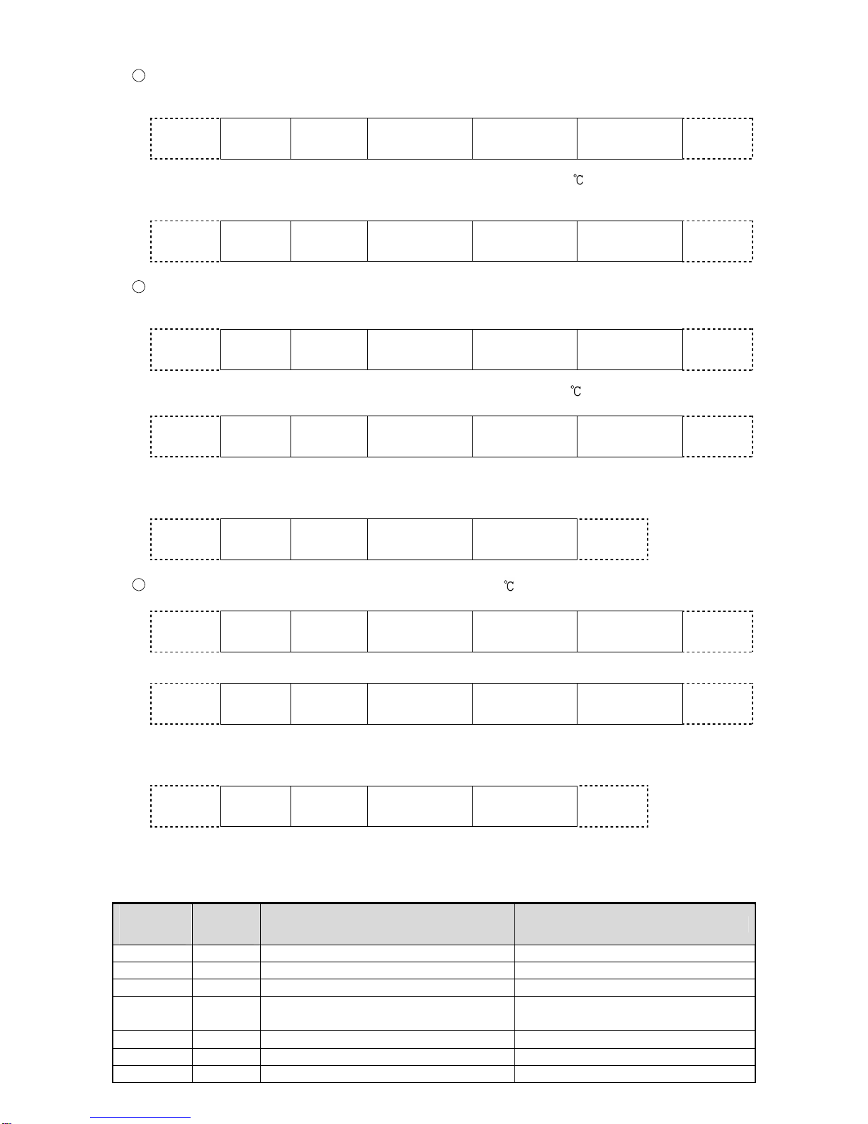
(3) Message example of ASCII mode
Numerals written below the command represent number of characters.
1Reading (Slave address 1, PV)
• A request message from the master
Amount of data means how many data items are to be read. It is fixed as 1 (30H 30H 30H 31H).
Header
(3AH)
Slave
address
(30H 31H)
Function
code
(30H 33H)
Data item
[0080H]
(30H 30H 38H 30H)
Amount of data
[0001H]
(30H 30H 30H 31H)
Error check
LRC
(37H 42H)
Delimiter
CR+LF
(0DH 0AH)
1 2 2 4 4 2 2
• Response message from the slave in normal status [When PV=600 (0258H)]
The number of response bytes means the number of bytes of data which has been read.
It is fixed as 2 (30H 32H).
Header
(3AH)
Slave
address
(30H 31H)
Function
code
(30H 33H)
Number of
response bytes
[02H]
(30H 32H)
Data
[0258H]
(30H 32H 35H 38H)
Error check
LRC
(41H 30H)
Delimiter
CR+LF
(0DH 0AH)
1 2 2 2 4 2 2
2Reading (Slave address 1, A1)
• A request message from the master
Amount of data means how many data items are to be read. It is fixed as 1 (30H 30H 30H 31H).
Header
(3AH)
Slave
address
(30H 31H)
Function
code
(30H 33H)
Data item
[0001H]
(30H 30H 30H 31H)
Amount of data
[0001H]
(30H 30H 30H 31H)
Error check
LRC
(46H 41H)
Delimiter
CR+LF
(0DH 0AH)
1 2 2 4 4 2 2
• Response message from the slave in normal status [When A1=600 (0258H)]
The number of response bytes means the number of bytes of data which has been read.
It is fixed as 2 (30H 32H).
Header
(3AH)
Slave
address
(30H 31H)
Function
code
(30H 33H)
Number of
response bytes
[02H]
(30H 32H)
Data
[0258H]
(30H 32H 35H 38H)
Error check
LRC
(41H 30H)
Delimiter
CR+LF
(0DH 0AH)
1 2 2 2 4 2 2
• Response message from the slave in exception (error) status (When a data item has been mistaken)
The function code MSB is set to 1 for the response message in exception (error) status [83H (38H
33H)].
The exception code 02H (30H 32H: Non-existent data address) is returned (error).
Header
(3AH)
Slave
address
(30H 31H)
Function
code
(38H 33H)
Exceptioncode
[02H]
(30H 32H)
Error check
LRC
(37H 41H)
Delimiter
CR+LF
(0DH 0AH)
1 2 2 2 2 2
3Setting (Slave address 1, A1) [When settingA1 to 600 (0258H)]
• A request message from the master
Header
(3AH)
Slave
address
(30H 31H)
Function
code
(30H 36H)
Data item
[0001H]
(30H 30H 30H 31H)
Data
[0258H]
(30H 32H 35H 38H)
Error check
LRC
(39H 45H)
Delimiter
CR+LF
(0DH 0AH)
1 2 2 4 4 2 2
• Response message from the slave in normal status
Header
(3AH)
Slave
address
(30H 31H)
Function
code
(30H 36H)
Data item
[0001H]
(30H 30H 30H 31H)
Data
[0258H]
(30H 32H 35H 38H)
Error check
LRC
(39H 45H)
Delimiter
CR+LF
(0DH 0AH)
1 2 2 4 4 2 2
• Response message from the slave in exception (error) status (When a value out of the setting range is set)
The function code MSBis set to 1 for the response messagein exception (error)status [86H (38H36H)].
The exception code 03H (30H 33H: Value out of the setting range) is returned (error).
Header
(3AH)
Slave
address
(30H 31H)
Function
code
(38H 36H)
Exceptioncode
[03H]
(30H 33H)
Error check
LRC
(37H 36H)
Delimiter
CR+LF
(0DH 0AH)
1 2 2 2 2 2
6.3 RTU Mode
8-bit binary data in command is transmitted as it is.
Data format Start bit: 1 bit
Data bit: 8 bits
Parity: No parity (Even, Odd) Selectable
Stop bit: 1 bit (2 bits) Selectable
Error detection: CRC-16 (Cyclic Redundancy Check)
Data interval: 3.5 character transmission times or less
To transmit continuously, an interval between characters which consist of one message,
must be within 3.5 character transmission times.

7
(1) Message configuration
RTU mode is configured to start after idle time is processed for more than 3.5 character transmissions,
and end after idle time is processed for more than 3.5 character transmissions.
3.5 idle
characters Slave
address Function
code Data Error check
CRC-16 3.5 idle
characters
Slave address
Slave address is an individual instrument number on the slave side, and is set within the range 0 to 95
(00H to 5FH).
The master identifies slaves by the slave address of the requested message.
The slave informs the master which slave is responding to the master by placing its own address in the
response message.
Slave address 0 (00H, broadcast address) can identify all the slaves connected. However, slaves do not
respond.
Function code
The function code is the command code for the slave to undertake the following action types.
Function code Contents
03 (03H) Reading the set value and information from slaves
06 (06H) Setting to slaves
Function code is used to discern whether the response is normal (acknowledgement) or if any error
(negative acknowledgement) has occurred when the slave returns the response message to the master.
When acknowledgement is returned, the slave simply returns the original function code.
When negative acknowledgement is returned, the MSB of the original function code is set as 1 for the
response.
For example, when the master sends request message setting 10H to the function code by mistake,
slave returns 90H by setting the MSB to 1, because the former is an illegal function.
For negative acknowledgement, the exception codes below are set to the data of the response
messages, and returned to the master in order to inform it of what kind of error has occurred.
Exception code Contents
1 (01H) Illegal function (Non-existent function)
2 (02H) Illegal data address (Non-existent data address)
3 (03H) Illegal data value (Value out of the setting range)
17 (11H) Shinko protocol error code 4 (Status unable to be set, e.g. AT is performing)
18 (12H) Shinko protocol error code 5 (During setting mode by keypad operation)
Data
Data differs depending on the function code.
A request message from the master side is composed of data item, amount of data and setting data.
A response message from the slave side is composed of the number of bytes, data and exception codes
in negative acknowledgements.
The amountof data to be dealt with in one message is “1”. Therefore the amount of data is fixed as (0001H).
The number of response bytes is (02H).
Effective range of data is –32768 to 32767 (8000H to 7FFFH).
Error check: 16 bit data to detect communication errors. Refer to “(2) Error check of RTU mode”.
(2) Error check of RTU mode
After calculating CRC-16 (Cyclic Redundancy Check) from the slave address to the end of the data, the
calculated 16-bit data is appended to the end of message in sequence from low order to high order.
How to calculate CRC-16
In the CRC-16 system, the information is divided by polynomial series. The remainder is added to the
end of the information and transmitted. The generation of polynomial series is as follows.
(Generation of polynomial series: X16 + X15 + X2+ 1)
1Initialize the CRC-16 data (assumed as X) (FFFFH).
2Calculate exclusive OR (XOR) with the 1st data and X. This is assumed as X.
3Shift X one bit to the right. This is assumed as X.
4When a carry is generated as a result of the shift, XOR is calculated by X of 3and the fixed
value (A001H). This is assumed as X. If a carry is not generated, go to step 5.
5Repeat steps 3and 4until shifting 8 times.
6XOR is calculated with the next data and X. This is assumed as X.
7Repeat steps 3to 5.
8Repeat steps 3to 5up to the last data.
9Set X as CRC-16 to the end of message in sequence from low order to high order.
8
(3) Message example of RTU mode
Numerals written below the command represent number of characters.
1Reading (Slave address 1, PV)
• A request message from the master
Amount of data means how many data items are to be read. It is fixed as 1 (0001H).
3.5 idle
characters Slave
address
(01H)
Function
code
(03H)
Data item
(0080H)
Amount of data
(0001H)
Error check
CRC-16
(85E2H) 3.5 idle
characters
1 1 2 2 2
• Response message from the slave in normal status [When PV=600 (0258H)]
The number of response bytes means the number of bytes of the data which has been read.
It is fixed as 2 (02H).
3.5 idle
characters Slave
address
(01H)
Function
code
(03H)
Number of
response bytes
(02H)
Data
(0258H)
Error check
CRC-16
(B8DEH) 3.5 idle
characters
1 1 1 2 2
2Reading (Slave address 1, A1)
• A request message from the master
The amount of data means the data item to be read. It is fixed as 1 (0001H).
3.5 idle
characters Slave
address
(01H)
Function
code
(03H)
Data item
(0001H)
Amount of data
(0001H)
Error check
CRC-16
(D5CAH) 3.5 idle
characters
1 1 2 2 2
• Response message from the slave in normal status [When A1=600 (0258H)]
Thenumberofresponsebytesmeansthenumberofbytesofthedatawhichhasbeenread.Itisfixedas2(02H).
3.5 idle
characters Slave
address
(01H)
Function
code
(03H)
Number of
response bytes
(02H)
Data
(0258H)
Error check
CRC-16
(B8DEH) 3.5 idle
characters
1 1 1 2 2
• Response message from the slave in exception (error) status (When data item is mistaken)
The function code MSB is set to 1 for the response message in exception (error) status (83H).
The exception code (02H: Non-existent data address) is returned (error).
3.5 idle
characters Slave
address
(01H)
Function
code
(83H)
Exceptioncode
(02H)
Error check
CRC-16
(C0F1H) 3.5 idle
characters
1 1 1 2
3Setting (Slave address 1, A1) [When settingA1 to 600 (0258H)]
• A request message from the master
3.5 idle
characters Slave
address
(01H)
Function
code
(06H)
Data item
(0001H)
Data
(0258H)
Error check
CRC-16
(D890H) 3.5 idle
characters
1 1 2 2 2
• Response message from the slave in normal status
3.5 idle
characters Slave
address
(01H)
Function
code
(06H)
Data item
(0001H)
Data
(0258H)
Error check
CRC-16
(D890H) 3.5 idle
characters
1 1 2 2 2
• Response message from the slave in exception (error) status (When a value out of the setting range is set)
The function code MSB is set to 1 for the response message in exception (error) status (86H).
The exception code (03H: Value out of the setting range) is returned (error).
3.5 idle
characters Slave
address
(01H)
Function
code
(86H)
Exception code
(03H)
Error check
CRC-16
(0261H) 3.5 idle
characters
1 1 1 2
7. Communication Command Table
When the data (set value) has a decimal point, a whole number (hexadecimal) without a decimal point is
used for a response.
Shinko
command
type
Modbus
function
code Data item Data
20H/50H 03H/06H 0001H: A1 value Set value, Decimal point omitted
20H/50H 03H/06H 0002H: A2 value Set value, Decimal point omitted
20H/50H 03H/06H 0003H: A3 value Set value, Decimal point omitted
20H/50H 03H/06H 0004H: Set value lock 0000H: Unlock 0001H: Lock 1
0002H: Lock 2 0003H: Lock 3
20H/50H 03H/06H 0005H: Sensor correction Set value, Decimal point omitted
20H/50H 03H/06H 0006H: Scaling high limit Set value
20H/50H 03H/06H 0007H: Scaling low limit Set value

9
Shinko
command
type
Modbus
function
code Data item Data
20H/50H 03H/06H 0008H: Decimal point place 0000H: XXXX (No decimal point)
0001H:XXX.X(1 digit after decimal point)
0002H:XX.XX(2 digits after decimal point)
0003H:X.XXX(3 digits after decimal point)
20H/50H 03H/06H 0009H: PV filter time constant Set value, Decimal point omitted
20H/50H 03H/06H 000AH: A1 hysteresis Set value, Decimal point omitted
20H/50H 03H/06H 000BH: A2 hysteresis Set value, Decimal point omitted
20H/50H 03H/06H 000CH: A3 hysteresis Set value, Decimal point omitted
20H/50H 03H/06H 000DH: A1 type
000EH: A2 type 0000H: No alarm action
0001H: High limit alarm
0002H: Low limit alarm
0003H: High limit alarm with standby
0004H: Low limit alarm with standby
20H/50H 03H/06H 000FH: A3 type 0000H: No alarm action
0001H: High limit alarm
0002H: Low limit alarm
0003H: High limit alarm with standby
0004H: Low limit alarm with standby
0005H: High/Low limit range alarm
20H/50H 03H/06H 0010H: Transmission output high limit Set value
20H/50H 03H/06H 0011H: Transmission output low limit Set value
20H/50H 03H/06H 0012H: A1 action Energized/
De-energized 0000H: Energized
0001H: De-energized
20H/50H 03H/06H 0013H: A2 action Energized/
De-energized 0000H: Energized
0001H: De-energized
20H/50H 03H/06H 0014H: A3 action Energized/
De-energized 0000H: Energized
0001H: De-energized
20H/50H 03H/06H 0015H: A1 action delay time Set value
20H/50H 03H/06H 0016H: A2 action delay time Set value
20H/50H 03H/06H 0017H: A3 action delay time Set value
20H/50H 03H/06H 0019H: Input type 0000H: K [–200 to 1370 ]
0001H: K [–199.9 to 400.0 ]
0002H: J [–200 to 1000 ]
0003H: R [0 to 1760 ]
0004H: S [0 to 1760 ]
0005H: B [0 to 1820 ]
0006H: E [–200 to 800 ]
0007H: T [–199.9 to 400.0 ]
0008H: N [–200 to 1300 ]
0009H: PL- [0 to 1390 ]
000AH: C (W/Re5-26) [0 to 2315 ]
000BH: Pt100 [–199.9 to 850.0 ]
000CH: JPt100 [–199.9 to 500.0 ]
000DH: Pt100 [–200 to 850 ]
000EH: JPt100 [–200 to 500 ]
000FH: K [–320 to 2500 ]
0010H: K [–199.9 to 750.0 ]
0011H: J [–320 to 1800 ]
0012H: R [0 to 3200 ]
0013H: S [0 to 3200 ]
0014H: B [0 to 3300 ]
0015H: E [–320 to 1500 ]
0016H: T [–199.9 to 750.0 ]
0017H: N [–320 to 2300 ]
0018H: PL- [0 to 2500 ]
0019H: C (W/Re5-26) [0 to 4200 ]
001AH: Pt100 [–199.9 to 999.9 ]
001BH: JPt100 [–199.9 to 900.0 ]
001CH: Pt100 [–300 to 1500 ]
001DH: JPt100 [–300 to 900 ]
10
Shinko
command
type
Modbus
function
code Data item Data
20H/50H 03H/06H 0019H: Input type 001EH: 4 to 20mA DC [–1999 to 9999]
001FH: 0 to 20mA DC [–1999 to 9999]
0020H: 0 to 1V DC [–1999 to 9999]
0021H: 0 to 5V DC [–1999 to 9999]
0022H: 1 to 5V DC [–1999 to 9999]
0023H: 0 to 10V DC [–1999 to 9999]
50H 06H 0070H: Key operation change flag
clearing 0000H: No action
0001H: Clear all
20H 03H 0080H: PV (input value) reading Current PV, Decimal point omitted
20H 03H 0081H: Status flag reading 0000 0000 0000 0000
215 to 20
20digit: A1 output
0: OFF 1: ON
21digit: A2 output
0: OFF 1: ON
22digit: A3 output
0: OFF 1: ON
23digit: Overscale
0: OFF 1: ON
24digit: Underscale
0: OFF 1: ON
25to 214 digit: Not used (Always 0)
215 digit: Change in key operation
0: No 1: Yes
Data
Notes about setting, reading command
• The data (set value, decimal) is converted to hexadecimal figures.A negative number is represented by
2's complement.
• A negative number is represented by 2's complement.
• When connecting multiple slaves, the address (instrument number) must not be duplicated.
• Modbus protocol uses Holding Register addresses. The Holding Register addresses are created as
follows.A Shinko command data item is converted to decimal number, and the offset of 40001 is added.
The result is the Holding Register address.
Using Data item 0001H (A1 value) as an example:
Data item in the sending message is 0001H, however, Modbus protocol Holding Register
address is 40002 (1 + 40001).
Setting command
• Setting range of each item is the same as that of keypad operation.
• When the data (set value) has a decimal point, a whole number (hexadecimal) without a decimal point is used.
• When Lock 3 is selected, all set values can be changed. However, they return to their previous value
after power is turned off because they are not saved in the non-volatile memory.
• If the alarm type is changed in [A1 type (000DH),A2 type (000EH),A3 type (000FH)], theA1, A2 or A3
value will default to “0”.Also alarm output status will be initialized.
• The Instrument Numbers and Communication Speed of the slave cannot be set by software
communication. They can only be set via the keypad.
• When sending a command by Global address [95 (7FH), Shinko protocol) or Broadcast address (00H,
Modbus protocol), the same command is sent to all the slaves connected. However, the response is not
returned.
• Up to 1,000,000 (one million) entries can be stored in non-volatile IC memory.
If the number of settings exceeds the limit, the data will not be saved. So, frequent transmission via
software communication is not recommended. (If a value set via software communication is the same
as the value before the setting, the value will not be written in non-volatile IC memory.)
Reading command
• When the data (set value) has a decimal point, a whole number (hexadecimal) without a decimal point
is used for a response.

11
Notes about programming monitoring software
How to speed up the scan time
Whenmonitoring multiple units of JIR-301-M, set the program so that the requisite minimum pieces of data such
as PV (0080H), status flag (0081H), etc. can be read. For other data, set the program so that they can be read
only when their set value haschanged. This will speed up the scan time.
How to read the set value changes made by front keypad operation
If any set value is changed by the keypad operation, the JIR-301-M sets [Status flag (0081H) 215: Change
in key operation] to [Yes (1)].
There are 2 methods of reading the set value changes made by the front keypad.
Reading method 1
(1) On the software side, check that [Status flag (0081H) 215: Change in key operation] has been set
to [Yes (1)], then read all set values.
(2) Clear the [Status flag (0081H) 215: Change in key operation], by setting the [Key operation change
flag clearing (0070H)] to [Clear all (0001H)].
If [Key operation change flag clearing (0070H)] is set to [Clear all (0001H)] during setting mode of the
JIR-301-M, Error code 5 (35H, Shinko protocol) or Exception Code 18 (12H, Modbus protocol) will be
returned as a negative acknowledgement. And [Statusflag (0081H) 215: Change in key operation] cannot
be cleared. Set a program so that all set values can be read when a negative acknowledgement is
returned.
(3) Read all set values again after acknowledgement is returned.
Reading method 2
(1) On the software side, check that [Status flag (0081H) 215: Change in key operation] has been set
to [Yes (1)], then set the [Key operation change flag clearing (0070H)] to [Clear all (0001H)].
(2) Set the program depending on the acknowledgement or negative acknowledgement as follows.
When acknowledgement is returned;
Consider it as settings completed, and read all set values.
When Error code 5 (35H, Shinko protocol) or Exception code 18 (12H, Modbus protocol) is returned
as a negative acknowledgement;
Consider it as still in setting mode, and read the requisite minimum pieces of data such as PV
(0080H), Status flag (0081H), etc. then return to step (1).
Thus, programs which do not affect the scan time can be created using the methods described above,
even if set values on the monitoring software will not be updated until settings are complete.
Note when sending all set values at one time
• When changing alarm types in [A1 type (000DH),A2 type (000EH),A3 type (000FH)],A1,A2 orA3 value
will default to “0”.Alarm output status will also be initialized.
First, sendA1,A2, A3 type, then sendA1,A2,A3 value.
• When changing input types in [Input type (0019H)], set values such asA1, OUT1 proportional band,A1
value, etc. will be initialized.
First, send the input type, thensendother set values.
When communicating with a PLC
To communicate with a PLC, use a Shinko PLC interface unit SIF-600. No programming is needed for
connection.
PLCs Corresponding to SIF-600:
PLC manufacturer PLC model Host link unit
MELSEC
Q series, QnA series (*) AJ71UC24,A1SJ71UC24-R2/R4/PRF
A1SJ71C24-R2/R4/PRF, QJ71C24
Mitsubishi Electric Corp.
MELSEC FX series (*)
Omron Corp. SYSMACCJ series CS1W-SCU21-V1
CJ1W-SCU21, CJ1W-SCU41
Keyence Corp. KV KV-L20V
Yokogawa Electric Corp. FA-M3 F3LC11-2N, F3LC11-1F, F3LC12-1F
Fuji Electric Co., Ltd. MICREX-SX series NP1L-RS1, NP1L-RS2, NP1L-RS3, NP1L-RS4
(*) Models with compatible QR/QW communication commands
12
8. Specifications
Cable length:Max. communication distance: 1.2 km
Cable resistance: Within 50 (Terminators are not necessary, but if used, use 120 or
more on one side.)
Communication interface: EIA RS-485
Communication method: Half-duplex communication
Synchronization method: Start-stop synchronization
Communication speed: 2400/4800/9600/19200 bps (Selectable by keypad) (Default: 9600 bps)
Code form: ASCII, binary
Communication protocol: Shinko protocol/ Modbus RTU/ ModbusASCII (Selectable by keypad)
(Default: Shinko protocol)
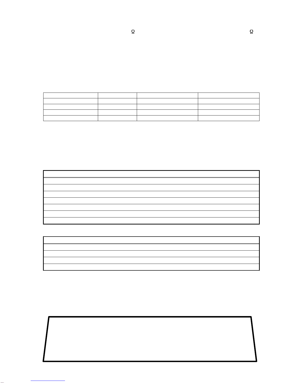
Data format:
Communication protocol Shinko protocol Modbus ASCII Modbus RTU
Start bit 1 1 1
Data bit 7 7 8
Parity Yes (Even) Yes (Even, Odd) No parity Yes (Even, Odd) No parity
Stop bit 1 1 or 2 1 or 2
Number of connectable units: Maximum 31 units to 1 host computer
Error correction: Command request repeat system
Error detection: Parity, checksum (Shinko protocol), LRC (ModbusASCII), CRC-16 (Modbus RTU)
9. Troubleshooting
If any malfunctions occur, refer to the following after checking the power supply to the master and the slave.
• Problem: Communication failure
Check if any of the following have occurred
Connection or wiring of the communication cable is not secure.
Burnout or imperfect contact on the communication cable and the connector.
Communication speed of the slave does not match that of the master.
The data bit, parity and stop bit of the master do not correspond to those of the slave.
The instrument number of the slave does not correspond to that of the command.
The instrument numbers are duplicated in multiple slaves.
Make sure that the program is appropriate for the transmission timing.
•Problem: Although communication is occurring, the response is 'NAK'.
Check if any of the following have occurred
A non-existent command code has been sent.
The setting command data exceeds the setting range of the slave.
The indicator cannot be set when functions such asAT are performing.
The JIR-301-M is in the front keypad operation setting mode.
For further inquiries, please contact our main office or dealers.
SHINKO TECHNOS CO., LTD.
OVERSEAS DIVISION
:Head Office
URL:
E-mail:
2-5-1, Senbahigashi, Minoo, Osaka, Japan
http://www.shinko-technos.co.jp
overseas@shinko-technos.co.jp
Tel :
Fax:
+81-72-727-6100
+81-72-727-7006
Other manuals for JIR-301-M
4
This manual suits for next models
1
Table of contents
Other Shinko Touch Panel manuals


