Shiv Expert User manual

USER MANUAL


CONTENTS
INTENDED USE..........................................................................................................................................................................1
SUPPLEMENTAL DOCUMENTATION ......................................................................................................................................1
GENERAL NOTES ABOUT ASSEMBLY....................................................................................... 1
BOLT SIZE / TOOLS / TORQUE SPECS ...................................................................................................................................2
TOOLS REQUIRED.....................................................................................................................................................................3
GENERAL NOTES ABOUT MAINTENANCE................................................................................. 3
WARRANTY................................................................................................................................................................................3
GEOMETRY.............................................................................................................................. 4
HARDWARE................................................................................................................................................................................5
1. FORK / STEM / HANDLEBAR INSTALLATION......................................................................... 7
1. INSTALLING THE FORK INTO THE STEERER TUBE ..........................................................................................................7
2. INSTALLING THE CARBON AERO HANDLEBAR ON THE AERO STEM..........................................................................8
3. INSTALLING THE ALLOY HANDLEBAR WITH A STANDARD 31.8MM STEM..................................................................9
4. INSTALLING THE EXPANDER PLUG AND TOP CAP..........................................................................................................11
2. HANDLEBAR EXTENSION / RISER INSTALLATION................................................................ 11
1. INSTALLING THE EXTENSION RISERS................................................................................................................................12
SYSTEM WITH NO RISER SPACERS:......................................................................................................................................13
SYSTEM WITH RISER SPACERS: ............................................................................................................................................13
2. INSTALLING THE CLAMPS, EXTENSIONS AND ARM PADS ............................................................................................14
3. ADJUSTING THE EXTENSIONS AND ARM PADS..............................................................................................................15
3. CABLE HOUSING / WIRE INSTALLATION .............................................................................. 17
1. INSTALLING THE BRAKE CABLE HOUSINGS AND SHIFTER WIRES..............................................................................17
2. ROUTING THE DERAILLEUR CABLES / WIRES AT THE BOTTOM BRACKET ...............................................................20
CABLE SYSTEM....................................................................................................................................................20
ELECTRONIC SYSTEM..........................................................................................................................................20
3. Di2 WIRING LOCATIONS.......................................................................................................................................................21
4. INSTALLING THE CABLE ROUTING COVER PLATE..........................................................................................................22
5. INSTALLING THE CABLE ROUTING CONTROL TOWER...................................................................................................22
4. BRAKE INSTALLATION......................................................................................................... 23
1. FRONT AND REAR BRAKE ASSEMBLY (Exploded view)...................................................................................................23
2. INSTALLING THE FRONT BRAKE ASSEMBLY...................................................................................................................24
3. INSTALLING THE REAR BRAKE ASSEMBLY......................................................................................................................25
4. ADJUSTING THE FRONT AND REAR BRAKE ASSEMBLIES ...........................................................................................26
5. SEATPOST INSTALLATION ................................................................................................... 27
1. INSTALLING AND ADJUSTING THE SHIV SEATPOST .......................................................................................................27
2. SEATPOST SETBACK OPTIONS..........................................................................................................................................29
6. FUELSELAGE INSTALLATION ............................................................................................... 30
1. INSTALLING THE FUELSELAGE ..........................................................................................................................................30
CLEANING THE RESERVOIR....................................................................................................................................................31
Please note all instructions and notices are subject to change and updates without notice.
Please visit www.specialized.com for periodic tech updates.
Feedback: [email protected]
SPECIALIZED BICYCLE COMPONENTS
15130 Concord Circle, Morgan Hill, CA 95037 (408) 779-6229
0000069864_UM_EN_R2, 01/18

1
SHIV USER MANUAL
IMPORTANT:
This user manual is specific to your Specialized Shiv bicycle. It contains important safety, performance and technical
information, which you should read before your first ride and keep for reference. You should also read the entire
Specialized Bicycle Owner’s Manual (“Owner’s Manual”), because it has additional important general information and
instructions which you should follow. If you do not have a copy of the Owner’s Manual, you can download it at no cost at
www.specialized.com, or obtain it from your nearest Authorized Specialized Retailer or Specialized Rider Care.
Additional safety, performance and service information for specific components such as suspension or pedals on
your bicycle, or for accessories such as helmets or lights, may also be available. Make sure that your Authorized
Specialized Retailer has given you all the manufacturers’ literature that was included with your bicycle or
accessories. If there is a difference between the instructions in this manual and the information provided by the
component manufacturer, please refer to your Authorized Specialized Retailer.
When reading this user manual, you will note various important symbols and warnings, which are explained below:
WARNING! The combination of this symbol and word indicates a potentially hazardous situation
which, if not avoided, could result in serious injury or death. Many of the Warnings say “you
may lose control and fall.” Because any fall can result in serious injury or even death, we do not
always repeat the warning of possible injury or death.
CAUTION: The combination of the safety alert symbol and the word CAUTION indicates a potentially
hazardous situation, which, if not avoided, may result in minor or moderate injury, or is an alert
against unsafe practices.
The word CAUTION used without the safety alert symbol indicates a situation which, if not avoided,
could result in serious damage to the bicycle or the voiding of your warranty.
INFO: This symbol alerts the reader to information which is particularly important.
GREASE: This symbol means that high quality grease should be applied as illustrated.
CARBON FRICTION PASTE: This symbol means that carbon friction paste should be applied as
illustrated to increase friction.
TORQUE: This symbol highlights the correct torque value for a specific bolt. In order to achieve
the specified torque value, a quality torque wrench must be used.
TECH TIP: Tech Tips are useful tips and tricks regarding installation and use.
INTENDED USE
The Specialized Shiv bicycle is intended and tested for road biking (condition 1) use only. For more information on
intended use and structural weight limits for the frame and components, please refer to the Owner’s Manual.
SUPPLEMENTAL DOCUMENTATION
For additional instructions, please refer to the Carbon Crank Instruction Guide IG0338 and techdocs.shimano.com
for all Shimano guides. Shiv installation videos are also available at http://servicevideos.specialized.com.
GENERAL NOTES ABOUT ASSEMBLY
This manual is not intended as a comprehensive assembly, use, service, repair or maintenance guide. Please see
your Authorized Specialized Retailer for all service, repairs or maintenance. Your Authorized Specialized Retailer
may also be able to refer you to classes, clinics or books on bicycle use, service, repair, and maintenance.

2
WARNING! Due to the high degree of complexity of the Shiv, proper assembly requires a high
degree of mechanical expertise, skill, training and specialty tools. Therefore, it is essential that the
assembly, maintenance and troubleshooting be performed by an Authorized Specialized Retailer.
WARNING! Many components on the Shiv, including, but not limited to, the handlebars, and the
stem, are proprietary to the Shiv. Only use originally supplied components and hardware at all
times. Use of other components or hardware will compromise the integrity and strength of the
assembly. Shiv specific components should only be used on the Shiv and not on other bicycles,
even if they fit. Failure to follow this warning could result in serious injury or death.
CAUTION: Do not face or ream the bottom bracket shell! This can prevent proper installation
of the crank. Your Specialized frame does not require any bottom bracket shell pre-installation
preparation, as all surfaces have been precisely machined to specific tolerances at the factory
for proper interface with OSBB/BB30 compatible crankset. Please refer to the manufacturer
instructions for crank and bottom bracket installation.
In order to successfully build the Shiv bicycle, it is very important to follow the order of operations
as outlined in this manual. Modifying the order of assembly will result in a longer build process.
BOLT SIZE / TOOLS / TORQUE SPECS
WARNING! Correct tightening force on fasteners (nuts, bolts, screws) on your bicycle is important
for your safety. If too little force is applied, the fastener may not hold securely. If too much force is
applied, the fastener can strip threads, stretch, deform or break. Either way, incorrect tightening
force can result in component failure, which can cause you to lose control and fall.
Where indicated, ensure that each bolt is torqued to specification. After your first ride, and
consistently thereafter, recheck the tightness of each bolt to ensure secure attachment of the
components. The following is a summary of torque specifications in this manual:
LOCATION Allen Key Spec Torque (in-lbf) Torque (Nm)
Stem @ steerer tube 4mm 45 5.1
Stem @ handlebar 4mm 45 5.1
Expander plug 6mm 80 9.0
Risers @ handlebar 4mm 80 9.0
Extension mount @ extension 4mm 40 4.5
Extension mount @ pad holder 4mm 40 4.5
Bottom bracket door 4mm 25 2.8
Control Tower 4mm 25 2.8
Brake mounting bolts 5mm 70 7.9
Brake cable pinch bolt 4mm 55 6.2
Brake pad 4mm 43 4.9
Saddle rail clamp 5mm 120 13.5
Seat collar 4mm 45 5.1
CAUTION: Ensure that all contact surfaces are clean and bolt threads are greased or have a
threadlocking compound (refer to the instructions for each bolt) prior to installation.

3
TOOLS REQUIRED
The following tools are required for assembly of this product:
2, 4, 5, 6mm Allen keys
4, 5, 6mm socket-style Allen keys
Flathead screwdriver (notched)
10mm wrench
Torque wrench
Cable and housing cutters
High-quality grease
Blue threadlocker (Loctite 242)
GENERAL NOTES ABOUT MAINTENANCE
The Specialized Shiv is a high performance bicycle. All regular maintenance, troubleshooting, repair and parts
replacement must be performed by an Authorized Specialized Retailer. For general information regarding maintenance
of your bicycle, please refer to the Owner’s Manual. In addition, routinely perform a mechanical safety check before
each ride, as described in the Owner’s Manual.
• Great care should be taken to not damage carbon fiber or composite material. Any damage may result in a loss of structural
integrity, which may result in a catastrophic failure. This damage may or may not be visible in inspection. Before each ride,
and after any crash, you should carefully inspect your bicycle for any fraying, gouging, scratches through the paint, chipping,
bending, or any other signs of damage. Do not ride if your bicycle shows any of these signs. After any crash, and before you
ride any further, take your bicycle to an Authorized Specialized Retailer for a complete inspection.
• While riding, listen for any creaks, as a creak can be a sign of a problem with one or more components. Periodically examine
all surfaces in bright sunlight to check for any small hairline cracks or fatigue at stress points, such as welds, seams, holes,
and points of contact with other parts. If you hear any creaks, see signs of excessive wear, discover any cracks, no matter
how small, or any damage to the bicycle, immediately stop riding the bicycle and have it inspected by your Authorized
Specialized Retailer.
• Lifespan and the type and frequency of maintenance depends on many factors, such as frequency and type of use, rider
weight, riding conditions and/or impacts. Exposure to harsh elements, especially salty air (such as riding near the ocean
or in the winter), can result in galvanic corrosion of components such as the crank spindle and bolts, which can accelerate
wear and shorten the lifespan. Dirt can also accelerate wear of surfaces and bearings. The surfaces of the bicycle should
be cleaned before each ride. The bicycle should also be maintained regularly by an Authorized Specialized Retailer, which
means it should be cleaned, inspected for signs of corrosion and/or cracks and lubricated. If you notice any signs of
corrosion or cracking on the frame or any component, the affected item must be replaced.
• Regularly clean and lubricate the drivetrain according to the drivetrain manufacturer’s instructions.
• Do not use a high pressure water spray directly on the bearings. Even water from a garden hose can penetrate bearing seals
and crank interfaces, which can result in increased bearing and crank wear, which can affect the normal function of the
bearings. Use a clean, damp cloth and bicycle cleaning agents for cleaning.
• Do not expose the bicycle to prolonged direct sunlight or excessive heat, such as inside a car parked in the sun or near a
heat source such as a radiator.
WARNING! Failure to follow the instructions in this section may result in damage to the components
on your bicycle and will void your warranty, but, most importantly, may result in serious personal injury
or death. If your bicycle exhibits any signs of damage, do not use it and immediately bring it to your
Authorized Specialized Retailer for inspection.
WARRANTY
A copy of the Specialized Limited Warranty Policy For Bicycles is provided with your bicycle, and is available from
your Authorized Specialized Retailer. It is also available for download at www.specialized.com.
4
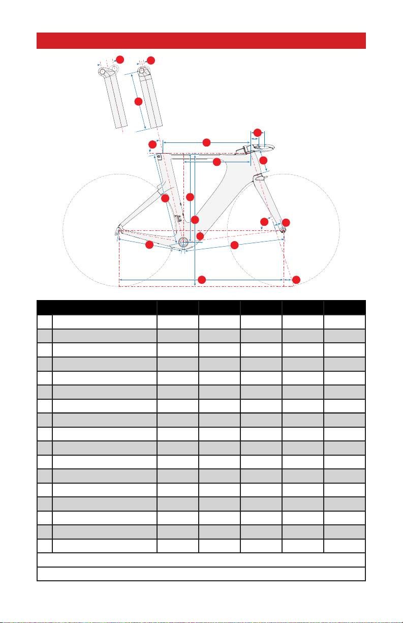
GEOMETRY
2
14
7
910
11
8
12
13
15
6
4
17
16
16
5
1
3
SIZE X-SMALL SMALL MEDIUM LARGE X-LARGE
1Frame Reach (mm) 365 385 405 425 445
2Frame Stack (mm) 495 515 540 565 590
3Stem Length, -18° Horizontal (mm) * 60 / 90 60 / 90 60 / 90 60 / 90 60 / 90
4
Seat Tube Length, BB Center to Top (mm)
505 525 551 577 603
5Top Tube Length (mm) 481 504 530 557 582
6BB Drop (mm) 72 72 72 72 72
7Chain-Stay Length (mm) 395 395 395 395 395
8Seat-Tube Angle (°) 77 77 77 77 77
9Head-Tube Angle (°) 70.25 71.5 72 72.5 72.5
10 Fork Rake (mm) 50 50 45 45 45
11 Trail (mm) 69 61 63 60 60
12 Front-Center (mm) 573 589 608 631 659
13 Wheelbase (mm) 957 973 992 1016 1043
14 Stand-Over Height (mm) 752 772 797 822 847
15 Head-Tube Length (mm) 99 115 139 163 189
16 Seat Post Setback (mm) **
+/- 12.5 / 37.5 +/- 12.5 / 37.5 +/- 12.5 / 37.5 +/- 12.5 / 37.5 +/- 12.5 / 37.5
17 Seat-Post Length (mm) 350 350 350 350 350
* 60mm or 90mm length options are for the Specialized aero stem.
** Two seatpost options available. +/- 12.5mm or +/- 37.5mm

5
HARDWARE
RISER CARBON BAR ALLOY BAR
STACK HEIGHT 20mm 10mm 5mm BOLT LENGTH BOLT LENGTH
0mm 25mm 30mm
5mm 1 30mm 35mm
10mm 1 35mm 40mm
15mm 1 1 40mm 45mm
20mm 1 45mm 50mm
25mm 1 1 50mm 55mm
30mm 1 2 55mm 60mm
35mm 1 1 1 60mm 65mm
40mm 2 65mm 70mm
45mm 2 1 70mm 75mm
50mm 2 2 75mm 80mm
55mm 2 1 1 80mm 85mm
60mm 3 85mm 90mm
65mm 3 1 90mm 95mm
70mm 3 2 95mm 100mm
75mm 3 1 1 100mm
6
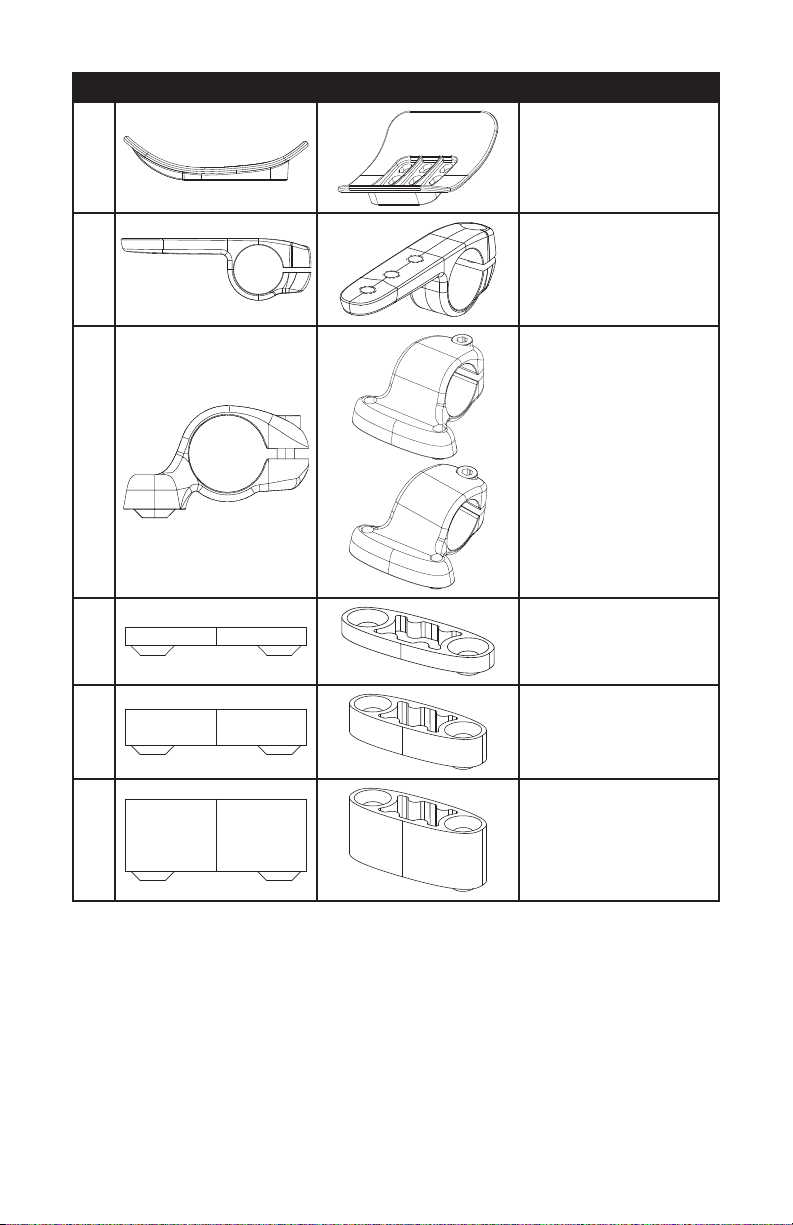
QTY ITEM SIDE VIEW ITEM ANGLED VIEW ITEM DESCRIPTION
2Arm pad holder
(requires 4 x M6x10mm bolts)
2 Pad holder clamp
2
0°
8°
0° or 8° Extension riser clamp
4 5mm extension riser
2 10mm extension riser
6 20mm extension riser
7
1. FORK / STEM / HANDLEBAR INSTALLATION
1. INSTALLING THE FORK INTO THE STEERER TUBE
Specialized Shiv frames are designed for use with the Specialized aero stem/handlebar combo or a 1 1/8” x 31.8mm
standard stem with the Specialized alloy aero handlebar. The Specialized aero handlebars work specifically with the
handlebar risers and extensions to offer the greatest range of position adjustment.
Before starting the assembly of the bike, install the seatpost in the frame as shown in Chapter 5.
WARNING! When placing the bicycle in a repair stand, clamp the seatpost using a frame clamp
specifically designed for thin-wall carbon tubes (for example, the Park Tools 100-X4 Extreme
Range Clamp). Clamping the seatpost with a standard clamp can cause damage to the seatpost
that may or may not be visible. Do not clamp the frame tubes.
For the initial setup, since the proper height is not yet determined, it is recommended to cut the
steerer tube at the highest position for assembly (2 x 25mm steerer tube spacers), then cut the
fork to the desired height once the build is complete and the bike has been fit to the rider.
To install the Aero stem in the lowest position (without spacers), it is recommended to place a
5mm spacer above the stem to retain enough steerer tube length in the event that a standard 1
1/8” stem is installed.
A
B
D
E
C
G
F
H
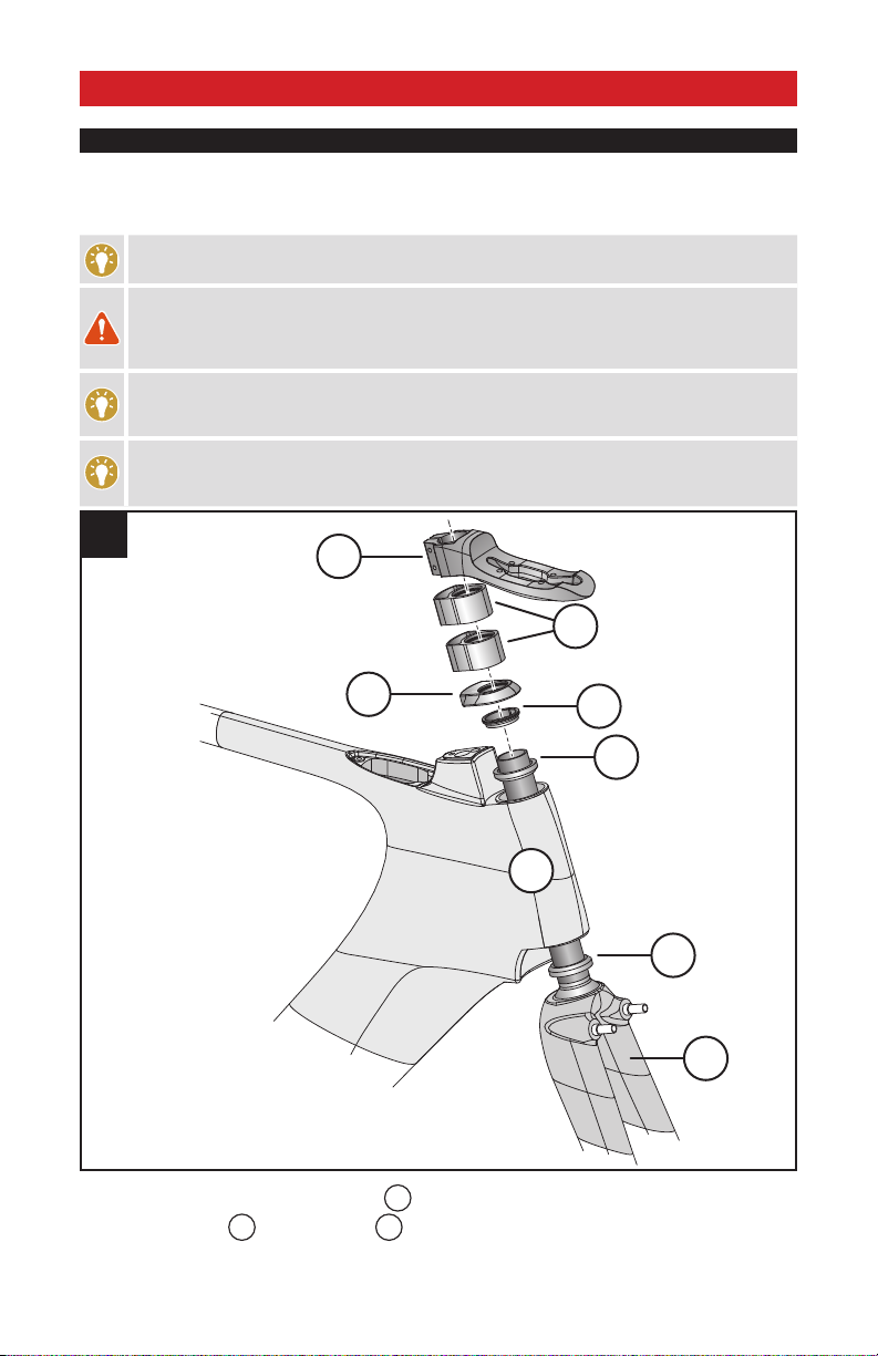
1
Fig.1: Install the lower 1 1/8” cartridge bearing
A
on the steerer tube of the fork.
Fig.1: Install the fork
B
into the head tube
C
of the Shiv frame and settle the bearing into the base of the
head tube.
8
Fig.1: Install the upper 1 1/8” cartridge bearing
D
on the steerer tube of the fork and settle the bearing into the
top of the head tube.
Fig.1: Install the bearing compression ring
E
over the bearing.
Fig.1: Install the top cap
F
over the compression ring.
Fig.1: Install 2 x 25mm head tube spacers
G
onto the steerer tube.
Fig.1: Install the stem
H
that will be used to build the bike onto the steerer tube. This is important to make sure
the steerer tube is cut to the correct length.
WARNING! Do not twist the stem onto the carbon steerer tube. This can result in damage to the
fork.
Mark the steerer tube directly above the stem, then remove the fork from the steerer tube. Make a 2nd mark
2mm below the original mark.
Place a steerer tube cutting guide tool on the steerer tube, with the guide slot aligned with the 2nd mark. Double-
check the measurement, so that the mark is 2mm below the top of the stem with 2x25mm spacers installed
below the stem.
Cut the steerer tube (using a carbon cutting blade, or a blade with a minimum 36 teeth) at the cut mark, remove
the tool, then remove any burrs from the top of the steerer using a fine grit sandpaper.
Repeat steps 1 through 7.
2. INSTALLING THE CARBON AERO HANDLEBAR ON THE AERO STEM
90mm
60mm
J
J
I
I
2
SPECIALIZED AERO STEM:
Fig.2: Determine the desired stem length of 60 or 90mm (longer 80 / 110mm stem available separately) and install
the carbon aero handlebar
I
along with the handlebar position wedge
J
.

9
If the stem length is not yet determined, it’s recommended to start at the 90mm (or 110mm) position.
Changing the stem from the 60mm to 90mm (or 80mm to 110mm) position will require that the cable
housings be replaced with longer ones to accommodate the additional stem length. It’s easier to trim cable
housings to a shorter length if adjusting from the 90mm to the 60mm (or 110mm to 80mm) position.
K
L
3
Fig.3: Apply grease to the bolts, then install the stem’s upper section
K
and four bolts
L
(M6x32mm, 4mm
countersunk Allen hex head).
Fig.3: Alternate the torque to the stem bolts in 5 in-lbf (0.6 Nm) increments, up to a final torque setting of 80 in-
lbf (9.0 Nm), to ensure an even load distribution to the handlebar.
3. INSTALLING THE ALLOY HANDLEBAR WITH A STANDARD 31.8MM STEM
4
N
M
10
STANDARD 31.8MM STEM:
Fig.4: Determine the desired stem
M
length and angle, then place the Specialized aero handlebar
N
into
the stem.
Fig.4: Orient the handlebar position horizontally, then torque the stem faceplate bolts to the manufacturer’s
specifications.
WARNING! Do not grease the interface between the stem and the alloy handlebar. Grease may
cause the handlebar to slip, which can result in a loss of control.
All edges of the stem in contact with the steerer tube should be rounded out to eliminate any stress points.
WARNING! Inspect the stem and steerer tube to ensure that there are no burrs or sharp edges.
Remove any burrs or sharp edges using fine grit sandpaper.
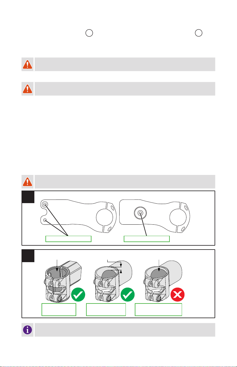
SPECIALIZED BRANDED STEMS:
Specialized multi-position stems are equipped with a shim and offer a near-continuous surface contact, which helps to
evenly distribute loads (fig. 2).
Specialized carbon road stems and Barmac Systems have built-in continuous surface contact, which helps to evenly
distribute loads.
Specialized SL stems with large bore holes are specifically designed in conjunction with Specialized forks with
carbon steerer tubes, to ensure proper load distribution (fig.2).
NON-SPECIALIZED BRANDED STEMS:
As we cannot test every combination, Specialized recommends against the use of non-Specialized branded stems
on Specialized carbon steerer forks equipped with Specialized steerer tube plugs, unless specified as original
equipment (fig.2).
WARNING! Non-Specialized stems may not be compatible with Specialized carbon steerer forks.
Failure to follow this warning could result in serious injury or death.
1
INTERNAL WEDGE CLAMPEXTERNAL SLOTTED CLAMP
2
SPECIALIZED MULTI-
POSITION STEM
(WITH SHIM)
SPECIALIZED SL STEM
WITH LARGE STEERER
TUBE BORE
NON-SPECIALIZED-BRANDED
STEM WITH LARGE STEERER
TUBE BORE
Full contact with
steerer tube
SL stem, with tested
surface area
Large hole, limited
surface area
Specialized recommends using an external slotted clamp style stem. Internal wedge clamp style
stems can cause damage to the steerer tube if improperly installed (fig. 1).
11
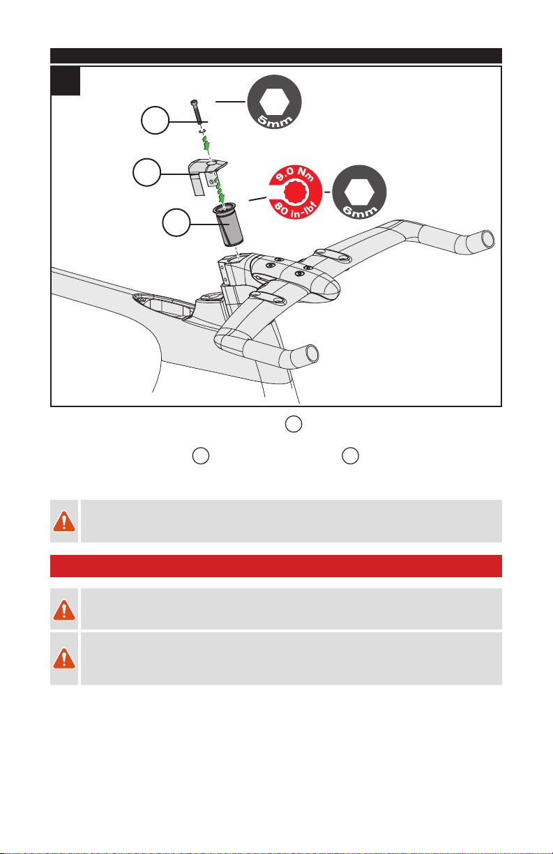
4. INSTALLING THE EXPANDER PLUG AND TOP CAP
O
P
Q
5
Fig.5: Install the Specialized 48mm Long Expander Plug
O
into the steerer tube, then torque to 80 in-lbf (9.0
Nm).
Fig.5: Install the preload top cap
P
, followed by the bolt with washer
Q
, then preload the headset bearings
to remove any play.
Fig.5: Torque the stem bolts to the manufacturer’s specifications.
WARNING! Carbon fiber steerer tubes require the use of the Long Expander Plug assembly
supplied with the fork. Do not use a star nut, as it can damage the inside surface of the steerer
tube. Damage to the steerer tube can result in failure, causing serious personal injury or death.
2. HANDLEBAR EXTENSION / RISER INSTALLATION
WARNING! Aerobars are attached to the front of your bicycle, and as a result, proper and secure
installation is critical for your safety. Improper installation or adjustment may result in an accident
which can cause serious injury or death.
WARNING! Aerobars can require riding positions that are new or different to many riders, which
may cause you to lose control and fall. Continue to look forward while riding and not down towards
the ground. Practice using these aerobars in a low traffic area to become accustomed to any
changes in the steering or handling of your bicycle.
12
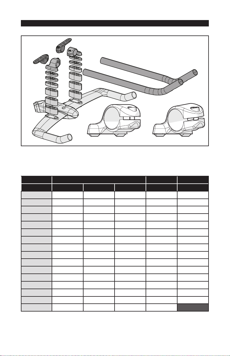
1. INSTALLING THE EXTENSION RISERS
EXPLODED PARTS VIEW:
0° bracket 8° bracket
These Aerobars can be adjusted in many ways to provide the ideal fit for the rider. Your Authorized Specialized
Retailer can help you find that ideal fit. The Specialized supplied risers allow for a range of extension height
adjustment (0-75mm height) and angle (0° and 8° brackets). Use the following Riser Chart to determine the correct
bolt length and use of supplied risers for the corresponding stack height:
RISER CARBON BAR ALLOY BAR
STACK HEIGHT 20mm 10mm 5mm BOLT LENGTH BOLT LENGTH
0mm 25mm 30mm
5mm 1 30mm 35mm
10mm 1 35mm 40mm
15mm 1 1 40mm 45mm
20mm 1 45mm 50mm
25mm 1 1 50mm 55mm
30mm 1 2 55mm 60mm
35mm 1 1 1 60mm 65mm
40mm 2 65mm 70mm
45mm 2 1 70mm 75mm
50mm 2 2 75mm 80mm
55mm 2 1 1 80mm 85mm
60mm 3 85mm 90mm
65mm 3 1 90mm 95mm
70mm 3 2 95mm 100mm
75mm 3 1 1 100mm

13
SYSTEM WITH NO RISER SPACERS:
1
Fig.1: Apply grease to the bolts, then install the bolts through the handlebar, through the risers and into the
extension brackets. Refer to the chart (see page 12) for the corresponding bolt length.
Fig.1: Torque the bolts to 80 in-lbf (9.0 Nm).
SYSTEM WITH RISER SPACERS:
5mm 10mm 15mm 20mm 25mm 30mm 35mm 40mm 45mm 50mm 55mm 60mm 65mm 70mm 75mm
C
2
Fig.2: Additional extension riser stack height can be achieved (5 to 75mm) by stacking different combinations of
riser parts
C
, in increments of 5mm. Refer to the chart (see page 12) for the corresponding bolt length.
* The alloy aero bars are equipped with a total of 10mm (2x5mm) of extension risers per side. Additional parts are
available to provide up to 70mm of extension riser height, in a separate Service Parts Kit.

14
2. INSTALLING THE CLAMPS, EXTENSIONS AND ARM PADS
3
H
Fig.3: Install the extensions
H
into the brackets and arm rest holders. If the extensions are difficult to insert
into the brackets, apply a light coat of grease to the opening of the bracket before installing the extensions.
The extensions have the option of being switched to either side, for a wider or narrower hand position. They can
also be rotated inward or outward to fine-tune the angle of the hand position (see page <OV>).
I
J
4
Fig.4: Apply grease to the bolts, then install the arm pad holders
I
on the extension clamps with 2 x pad
holder bolts and washers
J
(M6x10mm length, 4mm Allen hex round head bolts). The pad holders have three
lateral and three fore-aft position options (see page 15).

15
3. ADJUSTING THE EXTENSIONS AND ARM PADS
5
6
Fig.5: The arm pad mounting brackets can be positioned in front of or behind the extension clamp to fine-tune
the position under the arm.
Fig.6: The arm pads have three lateral and three fore-aft positions to fine-tune the rider’s elbow width and the
position of the pad under the arm.

16
7
8
Fig.7 & 8: The extensions and extension brackets have the ability to be swapped left to right, to adjust the
stance width of the hand grip area. They can also be moved fore-aft for length adjustment and rotated for
additional hand grip area width and angle fine-tuning.
Once the fit is determined, torque the riser bolts, extension clamp and pad holder bolts according to the torque
specifications listed in the chart on page 2.
Place the foam pads on the pad holders.

17
3. CABLE HOUSING / WIRE INSTALLATION
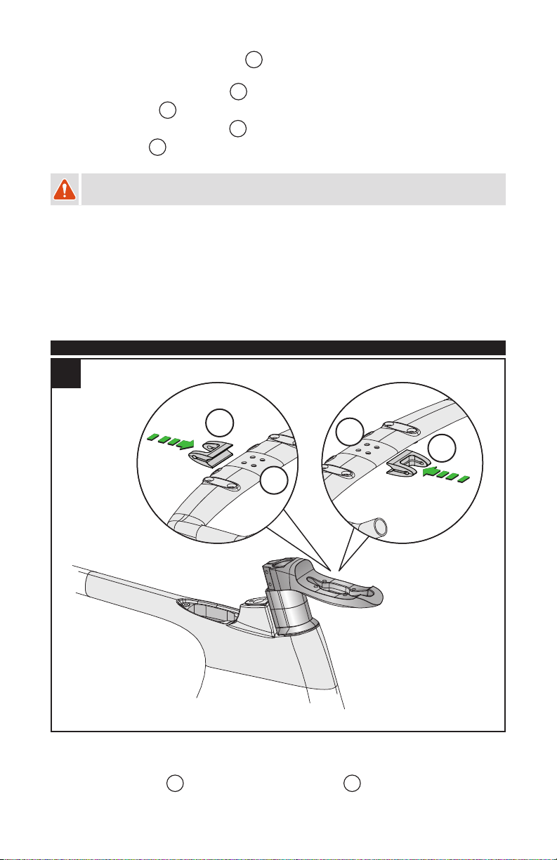
1. INSTALLING THE BRAKE CABLE HOUSINGS AND SHIFTER WIRES
AB
CD
1
Fig.1: Route a section of front brake cable housing
A
through the non-drive-side portion of the handlebar. If
running electronic shifters, route the electronic shifter wire
C
through the handlebar at before the cable housings,
and according to the manufacturer’s instructions. Be careful not to damage the wiring with the cable housing.
Fig.1: Repeat on the drive-side of the handlebar for the rear brake
B
and rear shifter
D
.
Fig.1: Trim the brake cable housings to the appropriate length once the brakes have been installed on the bike
(see chapter 4).
For Di2 instructions, refer to techdocs.shimano.com for Shimano guides.
BRAKE CABLE HOUSINGS
2
Fig.2: Route the rear brake cable housing through the small port hole in the top of the top tube.
Install the brake levers into the ends of the handlebar according to the manufacturer’s instructions.
Fig.2: Route the front brake cable housing to the front brake for later trimming.
This manual suits for next models
7
Table of contents
Other Shiv Bicycle manuals


