Shopsmith Mark VII User manual

Mark VII Restored Manual - V1.02 –Donated without cost to the world-wide Shopsmith Community - Everett L. Davis 2016 1

Mark VII Restored Manual - V1.02 –Donated without cost to the world-wide Shopsmith Community - Everett L. Davis 2016 2
WE KNOW YOU ARE ANXIOUS TO USE YOUR NEW SHOPSMITH - BUT
The features incorporated in SHOPSMITH are so unlike ordinary tools that you must learn to use them correctly
for maximum utility, safety and satisfaction. Before you even turn on the switch, read at least this page and
make the accuracy checks. At your very first opportunity study this entire manual, it will make you a better and
happier craftsman.
1. Always turn SPEED-DIAL to "slow" (below 1200) before changing from one operation to another. Never turn
SPEED-DIAL unless spindle is turning under power.
2. Always allow machine to come to full stop before turning key and pushing button to reverse rotation of spindle.
3. When mounting attachments to SHOPSMITH MARK VII always check to see that they are operating in correct
rotation. Never use any accessory arbor except the special 1/2" (Item No. 505505 and 5/8" (Item No. 505506)
arbors on the SHOPSMITH MARK VII. These arbors operate safely in either direction.
4. The auxiliary spindles (for Power Mount operation of accessory tools) of SHOPSMITH furnish a rotation for power
take off in a direction opposite to rotation furnished by the main spindle. In some instances the SHOPSMITH must
operate in "Reverse" to obtain proper rotation of an attachment on the main spindle.
5. When operating one tool on Power Mount and another on the main spindle, never exceed maximum safe speed
for the slowest tool.
6. For detailed instructions on SHOPSMITH techniques and operation see the book, POWER TOOL WOODWORKING
FOR EVERYONE, Item No. 505507.
SPEED DIAL SETTING
SHOPSMITH MARK VII SPEED-
DIAL (right) makes speed
selection as easy as dialing a
phone. Settings for most common
operations are engraved on the
dial. For more detailed
operational speed information
refer to the speed chart on the
back cover of the Parts Manual.
Turning the dial CLOCKWISE (with
motor on), increases speed;
turning COUNTERCLOCKWISE
decreases speed.
NEVER ATTEMPT TO CHANGE SPEEDS WHEN THE MOTOR IS TURNED OFF.
{You can bend things in the Speed Change Mechanism.}
MAKE IT A HABIT TO TURN SPEED-DIAL TO "SLOW" BEFORE SHUTTING OFF MOTOR FOR POSITION OR
ACCESSORY CHANGE. {You do not want an accessory that is rated for only slow speeds to come on in high.}

Mark VII Restored Manual - V1.02 –Donated without cost to the world-wide Shopsmith Community - Everett L. Davis 2016 3
TABLE OF CONTENTS
WE KNOW YOU ARE ANXIOUS TO USE YOUR NEW SHOPSMITH - BUT.................................................................. 2
SPEED DIAL SETTING ........................................................................................................................................... 2
TABLE OF CONTENTS............................................................................................................................................... 3
MARK VII NOMENCLATURE................................................................................................................................. 7
STANDARD ATTACHMENTS................................................................................................................................. 8
PLUG-IN INSTALLATION ...................................................................................................................................... 8
CHECKING FOR ACCURACY................................................................................................................................ 12
1- AT "0" TRUNNION SETTING, THE TABLE MUST BE SQUARE TO THE SAW BLADE ................................... 12
IF TABLE, WITH TRUNNION SET AT "0," IS NOT EXACTLY 90 DEGREES TO SAW BLADE ............................... 12
2TABLE SLOTS MUST BE PARALLEL TO SAW ................................................................................................ 12
IF TABLE SLOTS ARE NOT PARALLEL TO SAW BLADE .................................................................................... 13
3 THE MITER GAUGE, WHEN SET AT 90 DEGREES, MUST BE AT RIGHT ANGLES TO THE TABLE SLOTS. ...... 13
IF MITER GAUGE, AT 90 DEGREE SETTING, IS NOT EXACTLY SQUARE TO BLADE......................................... 14
4THE RIP FENCE, WHEN LOCKED, MUST BE PARALLEL TO THE TABLE SLOTS.............................................. 14
IF RIP FENCE IS NOT EXACTLY PARALLEL TO TABLE SLOTS............................................................................ 14
5THE EXTENSION TABLE MUST BE ALIGNED WITH SAW TABLE .................................................................. 14
IF IT IS NOT IN LINE ACROSS THE FRONT: ..................................................................................................... 14
IF IT IS NOT PARALLEL TO MAIN TABLE AFTER ABOVE CHECKS.................................................................... 15
SHOPSMITH 10-INCH SAW.................................................................................................................................... 16
NOMENCLATURE............................................................................................................................................... 16
HOW TO USE THE TABLE SAW .......................................................................................................................... 17
POSITIONING THE POWER HEAD.................................................................................................................. 17
MOUNTING THE SAW BLADE........................................................................................................................ 17
POSITIONING THE TABLE .............................................................................................................................. 17
BLADE PROJECTION....................................................................................................................................... 18
BLADE TO FENCE SETTINGS........................................................................................................................... 18
CROSSCUTTING ............................................................................................................................................. 19
MITER GAUGE SAFETY GRIP.......................................................................................................................... 19
MITER CUTS................................................................................................................................................... 19
CUTTING OFF DUPLICATE LENGTHS.............................................................................................................. 20
RIPPING ......................................................................................................................................................... 20
BEVEL RIPPING .............................................................................................................................................. 21
CROSS BEVELING........................................................................................................................................... 22

Mark VII Restored Manual - V1.02 –Donated without cost to the world-wide Shopsmith Community - Everett L. Davis 2016 4
COMPOUND ANGLE CUTS............................................................................................................................. 22
THE EXTENSION TABLE.................................................................................................................................. 22
SAW BLADES.................................................................................................................................................. 23
ARBORS ......................................................................................................................................................... 24
DADO TOOLS................................................................................................................................................. 24
MAGNA MOLDER .......................................................................................................................................... 25
SAW GUARDS-OPTIONAL.............................................................................................................................. 25
MITER GAUGE EXTENSION............................................................................................................................ 26
SHOPSMITH 16 1/2 INCH DRILL PRESS.................................................................................................................. 26
NOMENCLATURE............................................................................................................................................... 26
HOW TO USE THE DRILL PRESS ......................................................................................................................... 27
SETTING UP ................................................................................................................................................... 27
DRILLING ....................................................................................................................................................... 27
CONTROLLED DEPTH DRILLING..................................................................................................................... 28
PARALLEL DRILLING....................................................................................................................................... 28
JIG DRILLING.................................................................................................................................................. 29
FLOOR MODEL DRILL PRESS.......................................................................................................................... 29
V-BLOCK DRILLING ........................................................................................................................................ 30
MORTISING ................................................................................................................................................... 30
SHOPSMITH MARK VII SHAPER......................................................................................................................... 31
SETTING UP ................................................................................................................................................... 31
ROUTING WITH SHOPSMITH............................................................................................................................. 32
SHOPSMITH HORIZONTAL DRILL........................................................................................................................... 33
HOW TO USE THE HORIZONTAL DRILL.............................................................................................................. 33
DRILLING FOR BUTT DOWEL JOINTS............................................................................................................. 33
END DRILLING................................................................................................................................................ 33
JIG DRILLING.................................................................................................................................................. 33
CONCENTRIC DRILLING ................................................................................................................................. 34
OTHER OPERATIONS WITH HORIZONTAL SPINDLE........................................................................................... 34
WIRE BRUSHING................................................................................................................................................ 35
POLISHING AND BUFFING................................................................................................................................. 35
SHOPSMITH 16 1/2 INCH BY 34 INCH LATHE........................................................................................................ 37
NOMENCLATURE............................................................................................................................................... 37
HOW TO USE THE LATHE................................................................................................................................... 37

Mark VII Restored Manual - V1.02 –Donated without cost to the world-wide Shopsmith Community - Everett L. Davis 2016 5
MOUNTING SPINDLE WORK ............................................................................................................................. 38
ADJUSTING TOOL REST ..................................................................................................................................... 39
OFFSET TURNING .............................................................................................................................................. 39
TURNING TOOLS ............................................................................................................................................... 40
LATHE WORK ACCESSORIES .............................................................................................................................. 40
SHOPSMITH 10 INCH DISC SANDER ...................................................................................................................... 41
NOMENCLATURE............................................................................................................................................... 41
HOW TO USE THE DISC SANDER ................................................................................................................... 41
DRUM SANDER.............................................................................................................................................. 44
SANDPAPER................................................................................................................................................... 44
SHOPSMITH SPEED CAM-LOCKS ........................................................................................................................... 45
MAINTENANCE AND LUBRICATION ...................................................................................................................... 45
TUBULAR WAYS................................................................................................................................................. 45
BED TUBES......................................................................................................................................................... 45
QUILL................................................................................................................................................................. 45
BEARINGS.......................................................................................................................................................... 45
CAM-LOCKS....................................................................................................................................................... 45
ALL METAL SURFACES ....................................................................................................................................... 46
OILING PROCEDURE .......................................................................................................................................... 46
SLIDING SHEAVES.......................................................................................................................................... 46
GENERAL ....................................................................................................................................................... 46
OILING INTERMEDIATE SHAFT ...................................................................................................................... 46
OILING MOTOR SHAFT .................................................................................................................................. 46
ADDENDUM 1 - Supplemental information not in original manual ..................................................................... 47
Speed Changer Mark VII ................................................................................................................................... 47
Split Sheave Sets ........................................................................................................................................... 47
Table Assembly Nomenclature ......................................................................................................................... 48
Shaper Assembly Nomenclature....................................................................................................................... 48
Forward –Reverse –Safety Key Lock ............................................................................................................... 49
Rack Advance Mechanism ................................................................................................................................ 49
Inter-Latch Button............................................................................................................................................. 49
Eccentric for Lathe Tapering Adjustment ......................................................................................................... 50
Lathe Tapering Eccentric with Live Center........................................................................................................ 50
Levelling Block used for Pocket Screw Hole...................................................................................................... 50

Mark VII Restored Manual - V1.02 –Donated without cost to the world-wide Shopsmith Community - Everett L. Davis 2016 6
Using Mortising Hold Down.............................................................................................................................. 51
PARTS MANUAL .................................................................................................................................................... 52
Mark VII Headstock –PM2................................................................................................................................ 53
Mark VII Headstock Drive, Motor and Housing –PM4..................................................................................... 54
Mark VII Headstock Quill, Speed Control and Rack Advance –PM6 ................................................................ 55
Mark VII Base and Bed –PM8........................................................................................................................... 56
Mark VII Carriage and Table –PM10 ................................................................................................................ 56
Mark VII Fence, Miter Gauge and Grip –PM12................................................................................................ 57
Mark VII Tailstock, Tool Rest, Centers, Arbors, Saw & Sanding Disc –PM14................................................... 58
PART ILLUSTRATION REFERENCE NUMBERS TO PART NUMBERS AND DESCRIPTIONS........................................ 59
501210 A.O. Smith Motor with External Motor Start Relay Wiring ..................................................................... 72
507231 A.O. Smith Motor with Internal Centrifugal Motor Start Switch............................................................. 73
507232 G.E. Motor with Internal Centrifugal Motor Start Switch........................................................................ 74
MARK VII SPEED CHART ........................................................................................................................................ 75

Mark VII Restored Manual - V1.02 –Donated without cost to the world-wide Shopsmith Community - Everett L. Davis 2016 7
MARK VII NOMENCLATURE
1. POWER HEAD - Motor and all rotating parts totally enclosed in solid, pressure cast, aircraft quality aluminum alloy.
2. AUXILIARY SPINDLES - Extra spindles for dual mounting of complementary tools. Safety flat on upper spindle,
3. POWER HEAD TRAVERSE AND LOCK –Moves headstock to any position along tubular ways and locks it there.
4. TRAVERSE RELEASE - Instant release of traverse gearing for free-sliding power head when desired.
5. POWER MOUNT - For mounting extension table or major accessories such as Jointer or Jigsaw. One at each end.
6. HAND GRIP LOCKS - One at each end-positive lock for extension table, tailstock or accessories.
7. STOP SCREW - For vertical alignment in tilt-up position. Two at each end.
8. QUAD - TUBULAR BED –Center-less ground twin way tubes provide extreme rigidity and accuracy. Anti-corrosion
hard-chrome plated.
9. TRUNNION LOCKS - One at each end-secure SHOPSMITH in horizontal position - allow vertical operation at either
end.
10. SAFETY LATCH - Holds machine securely for vertical operation. One at each end.
11. STAND - Integral part of machine. Eliminates need to buy or build wood structure.
12. IMPELLER - Provides vacuum to remove sawdust, etc. from working areas.
13. VACUUM HOSE - Lightweight, flexible easy to handle.
14. RETRACTABLE CASTERS (OPTIONAL) - Permits ease in movement of unit.
15. EXTENSION TABLE - Mounts at either end of machine or to main table - affords exceptional capacity for sawing,
drilling, sanding, etc. Also usable as auxiliary table for upper auxiliary spindle.
16. TABLE - Raises, lowers, tilts 90° either direction.
17. CARRIAGE - Supports table or lathe tool rest. Slides on tubular ways. For carriage detail nomenclature
18. SPEED-DIAL - The correct speed for any operation merely by turning a dial.
19. FORWARD-OFF-REVERSE SWITCH - Key operated interlock for protection against accidentally turning on machine.
Removal of key renders machine inoperative.
Mark VII Restored Manual - V1.02 –Donated without cost to the world-wide Shopsmith Community - Everett L. Davis 2016 8
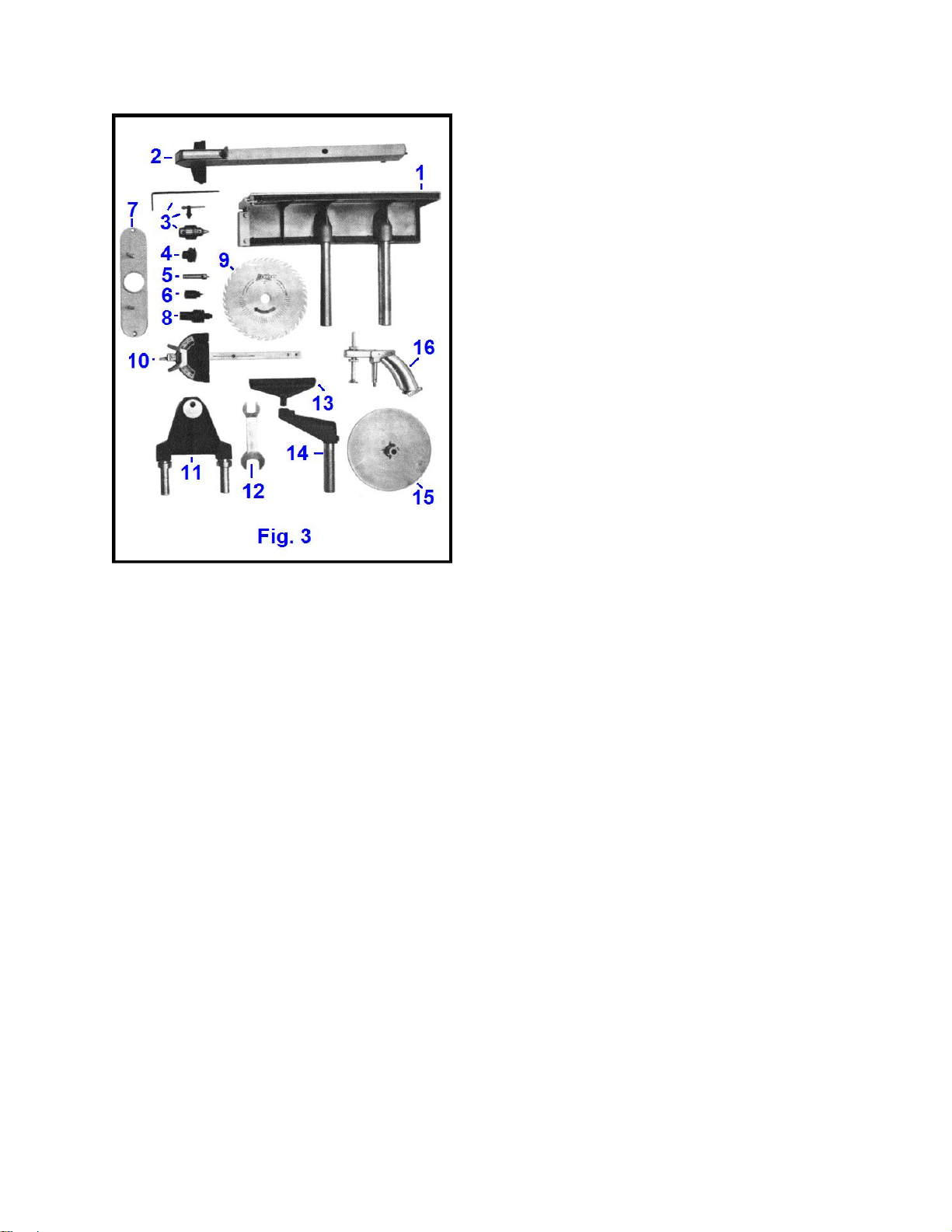
STANDARD ATTACHMENTS
(1) - Extension table - Mounts on either end of machine or to
table.
(2) - Rip fence - Used for ripping cuts on table saw. Also used as
guide, stop, support and jig for other operations.
(3) - Allen wrench, chuck and key - Jacobs chuck for tools with
5/64" - 1/2" diameter shanks. SHOPSMITH MARK VII Tool Kit.
(4) - 1-1/4" saw blade arbor - Special arbor for 9" and 10"
blades; attaches to main spindle and positions blade to minimize
run-out and wobble.
(5) - Cup center - For tailstock end of spindle turning. Seats in
tapered hole in eccentric cup mount.
(6) - Drive center - For spindle turning. Attaches to main spindle.
(7) - Shaper insert - For using shaper cutters or drum sander.
(8) - Universal arbor - 1/2" arbor with collars and spacers for
mounting shaper cutters or saw blades up to 8" diameter.
(9) - 10" saw blade - MAGNA all-purpose saw blade; used for
both crosscutting and ripping.
(10) - Miter gauge - Used for crosscutting and mitering operations on table saw. Also used as stop, guide and jig for many
other operations.
(11) -Tailstock - Holds eccentric for cup center mount.
(12) - Spanner wrench - for saw arbor.
(13) - Lathe tool rest - Guide and support for lathe turning tools.
(14) - Tool rest arm and post - Used in front hole of table carriage to support lathe tool rest.
(15) - Sanding disc - Double sided 10" sanding disc; one side flat and one side tapered for greatest versatility. Attaches to
spindle---balanced for vibration-free operation.
(16) - Miter Gauge Safety Grip - Provides added safety and accuracy and facilitates use of Miter Gauge.
PLUG-IN INSTALLATION
SHOPSMITH MARK VII is normally delivered set up and ready to go. All you have to do is plug it in. If for some
special reason you have SHOPSMITH MARK VII delivered in the crate, you can quickly set it up, following
directions.
CAUTION - Before starting the motor check your line fuses. Because a powerful motor draws an initial starting
load greater than required during continuous running, it is good practice to equip the circuit supplying current
to the machine with a DELAYED ACTION FUSE. This is the same type fuse called for on circuits for washing
machines, driers, and other household appliances. Operate the unit on a separate unloaded circuit.
If an extension cord is required it must be not smaller than #12 wire and no longer than 25 feet.
All electrical appliances should be grounded when in use. Be sure the SHOPSMITH power cord is plugged
into a grounded outlet.

Mark VII Restored Manual - V1.02 –Donated without cost to the world-wide Shopsmith Community - Everett L. Davis 2016 9
ASSEMBLY OF MARK VII STAND
There are pre-punched holes in each foot for mounting retractable casters, an extremely useful accessory which
makes SHOPSMITH a mobile unit easily relocated anywhere in
or outside the home or shop. Item No. 505500.
AFTER UNCRATING, SET UP THE STAND AS FOLLOWS:
1. Attach end frames to base rails using three 1/4 - 20 x 1/2 hex
head bolts with 1/4" nuts and lock washers at each attachment
area. (Fig. 4) Leave bolts finger tight until step 7.
2. Mount deck on top of end frames with deck flange
on outside. Fasten with sixteen 1/4 - 20 x 3/8 truss
head screws, with nuts and lock washers (Fig. 5).
Screw heads go outside. Leave all screws finger tight
until step 7.
3. Assemble feet to rails. Turn unit upside down.
Push four #1024 Tinnerman nuts onto rail end
flanges, using outer pair and inner pair of holes only
(Fig. 6). Make certain that the plain round hole is on outside of flange. If accessory
retractable casters are to be mounted, put Tinnerman nuts (from caster package) on
middle holes also. See direction sheet supplied with casters.
Assemble foot by engaging lip of top of foot and then bringing flange
mounting holes into line using a rolling action (Fig. 7). Assemble screws
into Timmerman nuts. When all screws have been engaged, tighten
firmly.
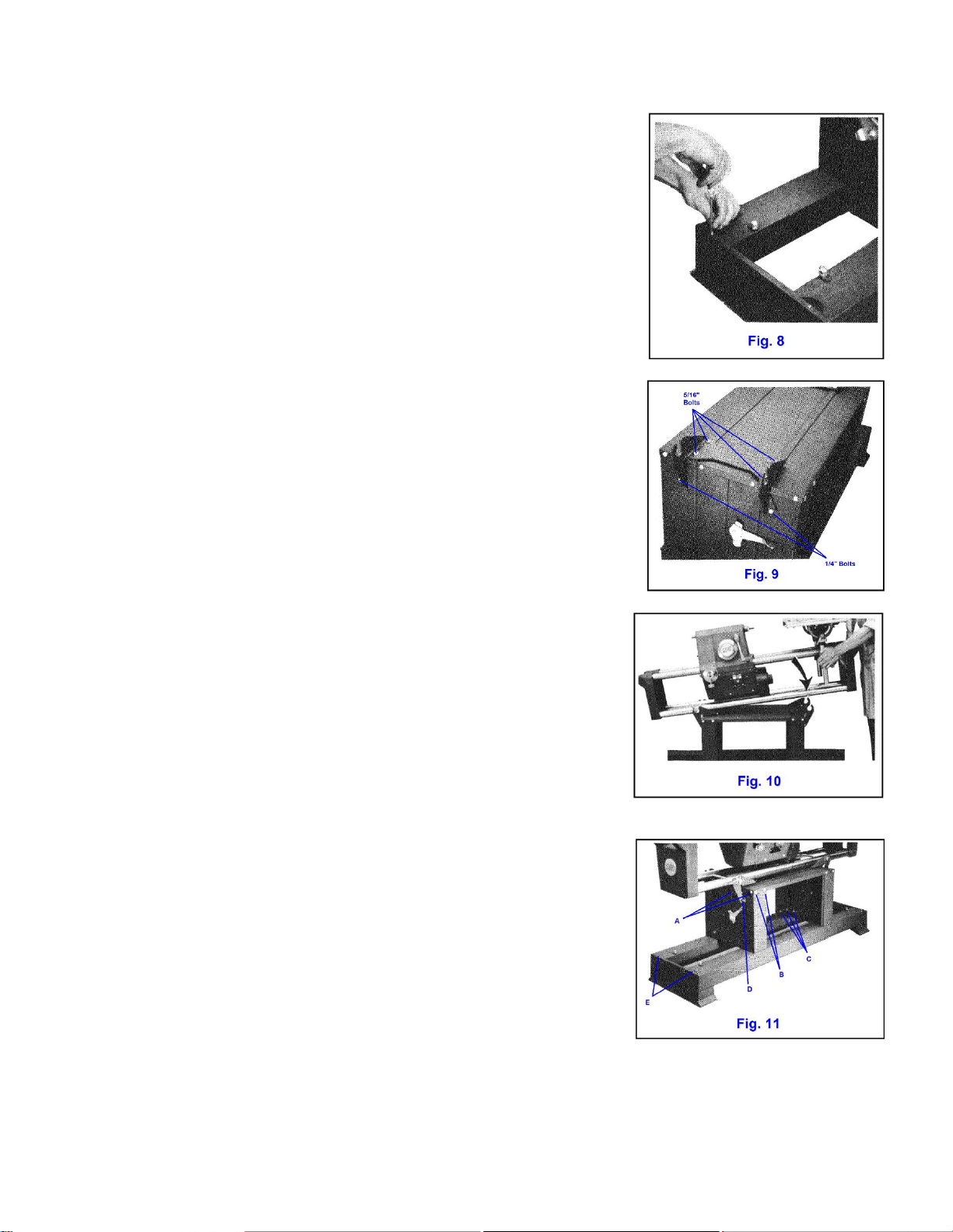
Mark VII Restored Manual - V1.02 –Donated without cost to the world-wide Shopsmith Community - Everett L. Davis 2016 10
Turn stand right side up and install #6x3/8 sheet metal screw through top
lip of foot into each rail (Fig. 8). Leave them slightly loose until step 7.
4. Mount trunnion brackets on each end of stand (Fig. 9), using four 5 16
-18 x 5/8 hex head bolts with 11/32 x 11/16 plain washers and 5/16 lock-
washers and nuts on the underside to attach each bracket to deck. Leave
these bolts finger tight.
Use two 1/4 -20 x 1/2 hex head bolts, lock washers and nuts on each end
to attach to end frames. Leave these bolts quite loose.
5. Mount tubular bed and power head assembly. Determine front of
stand: Safety latches (No. 10, Fig. 2) are nearer front side. Position
trunnion handles (No. 9, Fig. 2) at 45° so that keys of trunnion are vertical
and set power head and bed assembly in the brackets (Fig. 10). Jockey
brackets until trunnion keys at both ends seat properly and then lock in
place by turning handles down to horizontal position.
6. Tighten trunnion brackets. With trunnions locked, center brackets on
stand both sideways and endways. Then tighten to eight 5/16" bolts
through the deck.
7. "Levelize" the stand. The stand is designed to adapt to small variations
of floor flatness. To adjust stand to your floor, locate the unit where it is
intended to be used and, with headstock centrally positioned on the
ways, grasp headstock and jostle it forward and backward several times.
Refer to Fig. 11 and start by tightening the four truss head screws "A" on
each end of deck (Total 8). Next tighten the eight truss head screws "B"
on front and back of deck. Then tighten the twelve hex bolts "C" holding
end frames to rails and the four 1/4" bolts "D" holding trunnion brackets
to end frames. Last, tighten sheet metal screws "E" at end of rails.
Mark VII Restored Manual - V1.02 –Donated without cost to the world-wide Shopsmith Community - Everett L. Davis 2016 11
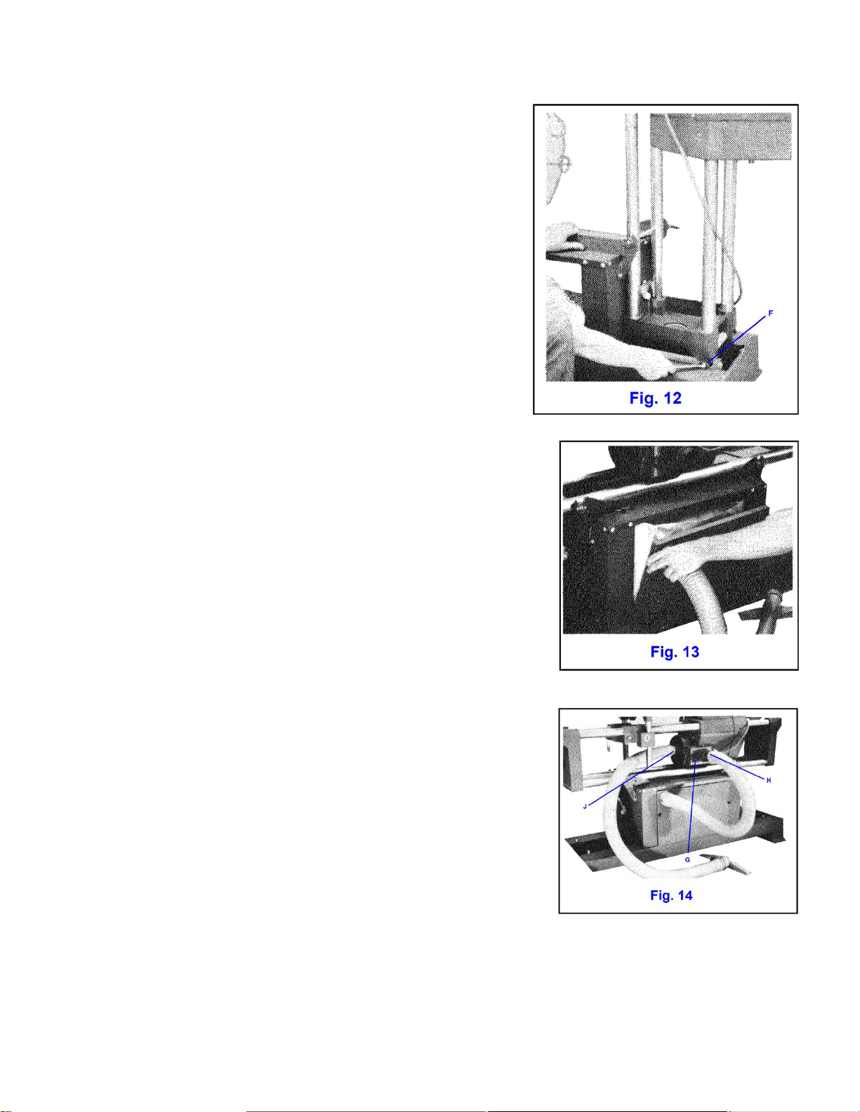
8. Adjust tilt-up stops. Unlock Trunnion on one end and tilt
machine unit to vertical on opposite end. Safety latch handles
should be pointing up.
Adjust stop screws on top of rails ("F", Fig. 12) until bed tubes are
square with stand top. Use carpenter square and sight across
tubes. Tighten stop screw jam nuts. Safety latch should now
engage lower lip of end cap. Some springing of the end frame is
normal when engaging safety latch.
Return machine to horizontal and lock trunnion. Adjust stop
screws for other end in same manner.
9. Install front panel. Return machine to horizontal and install
front panel using #6 - 32 x 1 truss head screws and Tinnerman
nuts, one each in middle on each side.
10. Install rear panel. Unfold sawdust vacuum bag and lay it on inside
of rear panel so that bag matches panel and inlet tube of bag lines up
with large flanged hole in panel. Tuck tube about one inch through
hole and spread it so that one end of the short hose can be inserted.
Make sure bag is still square with panel and secure it by pushing hose
adapter into panel hole, thereby sealing hose to bag tube. Mount rear
panel with hose at upper left corner, (Fig. 13) using the two #6 plastic
head thumb screws and Tinnerman nuts. Rest bottom of bag on rear
rail.
11. Connect discharge hose. Plug other end of hose into impeller
outlet duct opening ("G", Fig. 14). On some units the duct has two
outlets, one direct and one offset ("H"). The offset opening allows
vacuum to be used when carriage is next to headstock. Plug unused
hole with push-in plastic cap provided.
12. Connect vacuum hose. Plug long hose into impeller housing inlet
("J", Fig. 14) and your machine is ready to run.
BEFORE OPERATING YOUR SHOPSMITH MAKE THE ACCURACY CHECKS
WHICH FOLLOW IMMEDIATELY ON NEXT PAGE
Mark VII Restored Manual - V1.02 –Donated without cost to the world-wide Shopsmith Community - Everett L. Davis 2016 12
CHECKING FOR ACCURACY
A good craftsman makes periodic checks of his machine
to be sure that related parts are in correct alignment.
Here is what to look for and good methods for checking.
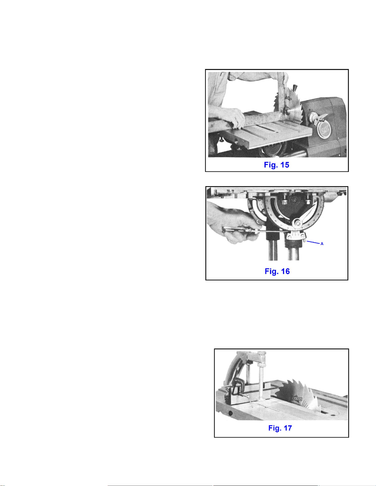
1- AT "0" TRUNNION SETTING, THE TABLE MUST
BE SQUARE TO THE SAW BLADE
This is checked with the table as low as possible and
locked in position about 1/8" away from the saw blade.
Be sure the square used for checking rests flat against
the blade and that it seats between the teeth.
IF TABLE, WITH TRUNNION SET AT "0," IS NOT
EXACTLY 90 DEGREES TO SAW BLADE
Loosen table tilt lock and pull out trunnion plunger ("A",
Fig. 16). Set table at exactly 90 degrees and secure table
tilt lock. Push in plunger turn auto - stop set screw until
it just bears against plunger (Fig. 16). Adjust trunnion
vernier plate until middle calibration is lined up exactly
with "0" mark on trunnion.
Pull out plunger and tilt table to the right until middle calibration on trunnion vernier plate lines up exactly with
45 degree mark on trunnion. Lock table. Push in plunger and adjust auto-stop set screw until it just bears against
plunger.
2TABLE SLOTS MUST BE PARALLEL TO SAW
BLADE. Check by setting table as low as possible in normal
sawing position. Place miter gauge in either slot and clamp
Allen wrench to its face so that it extends just enough to
touch one tooth of the blade set In direction of miter gauge
(Fig. 17). Mark tooth with a pencil or chalk. (Miter gauge
stop rod, if available, may be used in place of Allen wrench.)
Rotate saw blade backwards by hand until that SAME tooth
is at rear of the insert slot.

Mark VII Restored Manual - V1.02 –Donated without cost to the world-wide Shopsmith Community - Everett L. Davis 2016 13
Move the miter gauge ahead and check to see if Allen
wrench just barely touches that same tooth (Fig 18).
IF TABLE SLOTS ARE NOT PARALLEL TO SAW BLADE
Loosen four hex head cap screws which secure table to
trunnions (No, 20, Fig. 26). Do not loosen more than one
full turn. Tap table lightly with hammer handle or wood
block to "rotate" it into correct alignment (Fig. 19).
Before tightening screws, check for extension table
alignment, step 5. Lock by tightening the four cap screws,
turning each one a small amount, then repeat until each is
secure.
3 THE MITER GAUGE, WHEN SET AT 90 DEGREES,
MUST BE AT RIGHT ANGLES TO THE TABLE SLOTS.
To check, set miter gauge in either slot and use a square
as shown (Fig. 20). Be sure that one arm of square is held
firmly against face of miter gauge and the other is flush
against side of the second table slot.
Mark VII Restored Manual - V1.02 –Donated without cost to the world-wide Shopsmith Community - Everett L. Davis 2016 14
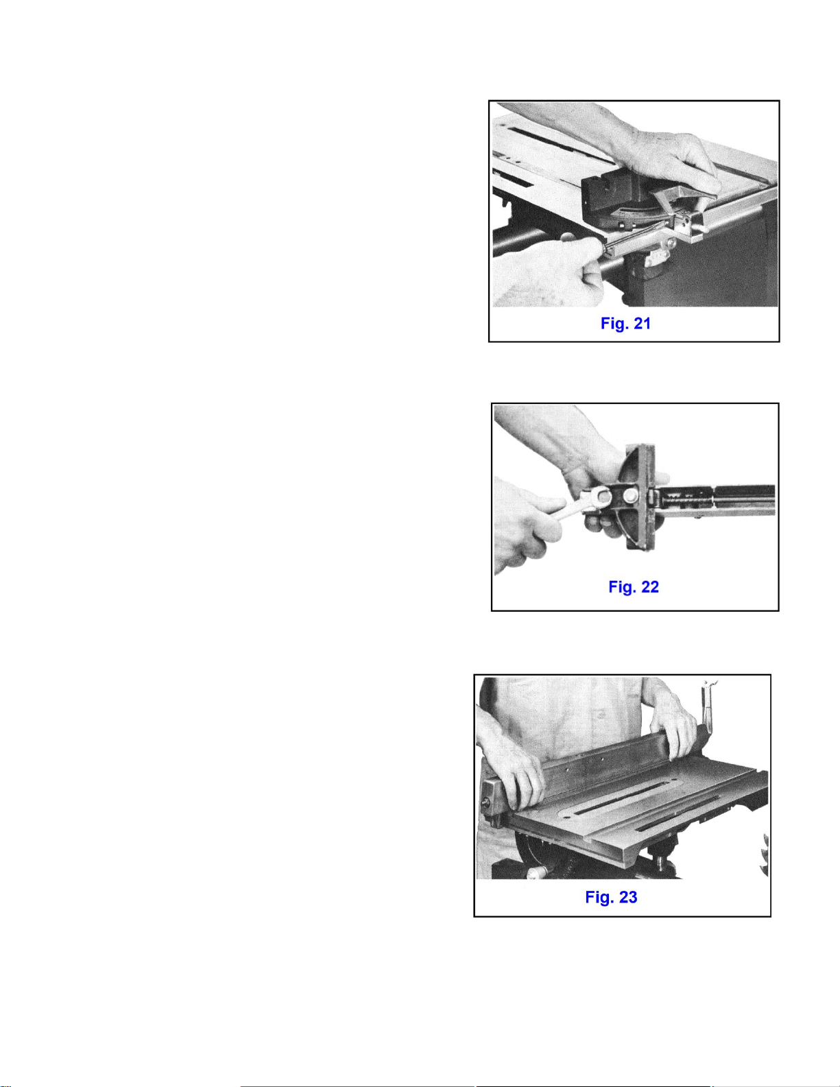
IF MITER GAUGE, AT 90 DEGREE SETTING, IS NOT
EXACTLY SQUARE TO BLADE
Raise lock lever and pull out miter gauge plunger (No. 3, Fig.
25). Adjust miter gauge head exactly square to blade and
lock in place.' Push in plunger and adjust auto-stop set screw
until it just bears against plunger (Fig. 21). Adjust miter gauge
vernier plate until middle "calibration is lined up exactly with
90 degree mark on miter gauge.
Unlock and turn miter gauge head until center vernier plate
mark is lined up with 45 degree mark on miter gauge. Push
in plunger and adjust 45 degree auto-stop set screw until it
bears against plunger. Make a similar adjustment on the opposite 45 degree auto-stop.
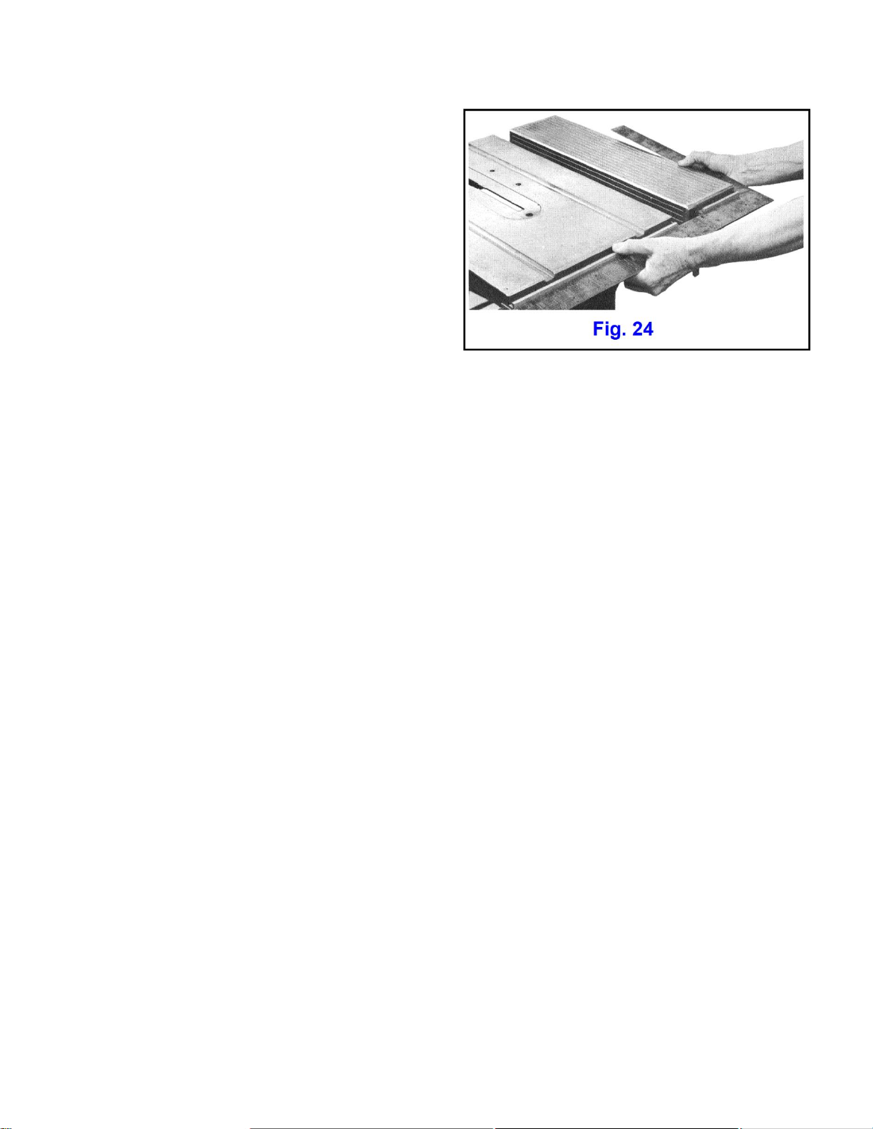
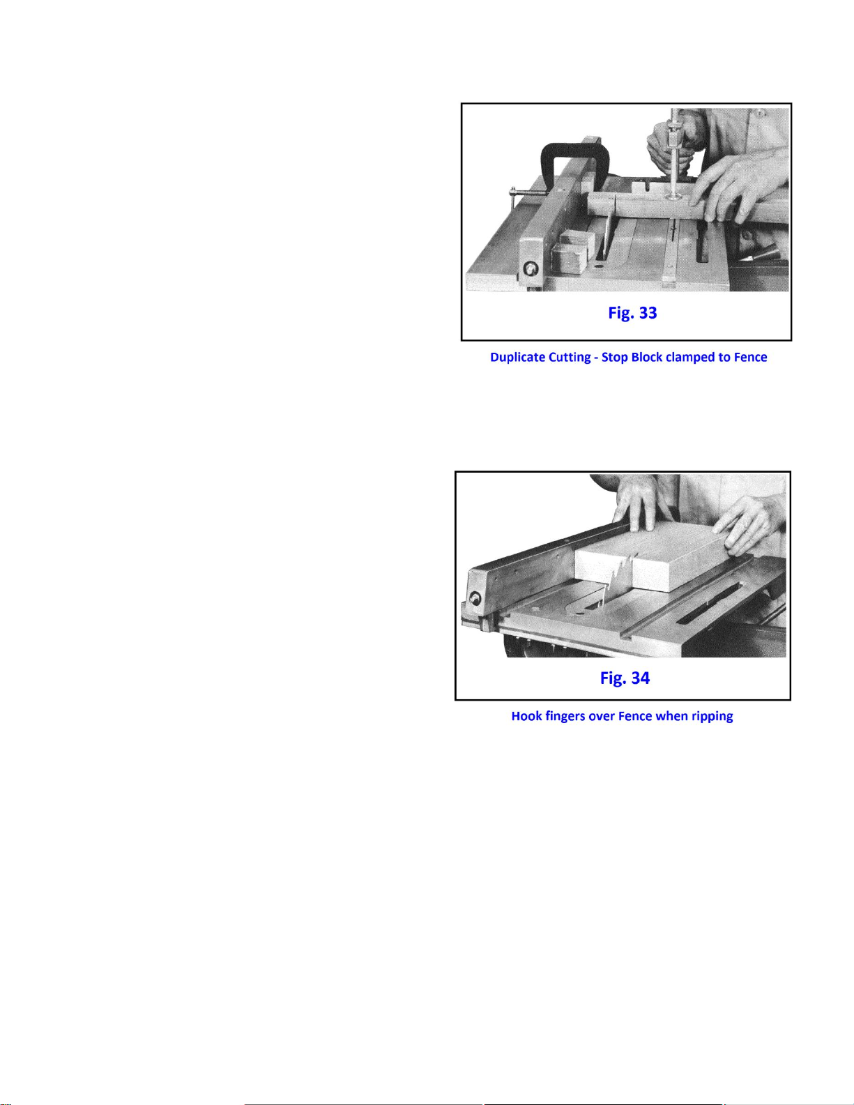
4THE RIP FENCE, WHEN LOCKED, MUST BE PARALLEL
TO THE TABLE SLOTS
Check by locking rip fence on table, positioned so that one
side of fence is flush with one side of either table slot.
IF RIP FENCE IS NOT EXACTLY PARALLEL TO TABLE
SLOTS
Loosen the two cap screws which secure fence to base
casting (Fig. 22). By feeling with finger tips at both ends of
fence, set fence exactly parallel to either table slot (Fig. 23)
and lock by depressing locking handle. Retighten the two cap
screws while fence is locked in position.
5THE EXTENSION TABLE MUST BE ALIGNED WITH
SAW TABLE
Check by setting extension table to height of saw table and
moving carriage to extreme right end. Place a straight
edge across front edges of table bars (Fig. 24).
IF IT IS NOT IN LINE ACROSS THE FRONT:
Loosen the four cap screws which secure saw table to
trunnions (No. 20. Fig. 26). Tap saw table forward or back
until front edge of table bar is in line with edge of
extension table bar. Retighten four cap screws turning
each a small amount until all four are secure. Recheck saw
table for alignment with saw blade as covered by step 2.
Mark VII Restored Manual - V1.02 –Donated without cost to the world-wide Shopsmith Community - Everett L. Davis 2016 15
IF IT IS NOT PARALLEL TO MAIN TABLE AFTER
ABOVE CHECKS
Loosen the four set screws holding the end cap (part
501542) to way and bed tubes. Tap the end cap out
on front edge and in on rear edge, or vice versa as
required, until tables are parallel. Tighten all our set
screws securely.

Mark VII Restored Manual - V1.02 –Donated without cost to the world-wide Shopsmith Community - Everett L. Davis 2016 16
SHOPSMITH 10-INCH SAW
NOMENCLATURE
1. Rip fence lock handle - Depressing handle into fence automatically squares fence to table and locks it front and
rear.
2. Angling screws - To set fence slightly out of parallel, for special set ups or operations, without disturbing basic
parallel setting of fence.
3. Miter gauge plunger - Pin against which auto-stop set screws bear at 45, 90 and 45 degrees.
4. Safety grip - Provides safe, positive grip for square or angle cuts.
5. Miter gauge lock - Locks miter gauge settings.
6. Miter gauge extension slots - For mounting miter gauge extensions.
7. Miter gauge lock screw - Locks miter gauge in table slot for jig setting.
8. Insert - Removable insert is coined and “bowed" for accurate, flush fit; integral projections prevent saw blade
cutting insert.
9. Stop rod holes - Permit mounting of miter gauge stop rods for duplicate cutting.
10. Saw blade - 10" all-purpose blade furnished. Always mounted on main spindle.
11. Saw arbor - 1-1/4" - Blade stays mounted on arbor - Tools can be changed in seconds
12. Table tubes - Rack cut for raising or lowering table.
13. Inter latch release - Pushing button releases latch. Pulling button engages latch.
14. Inter latch rod - Latches carriage to headstock at sawing position for either table slot.
15. Table tilt locks - Lock table at any angular setting, both front and rear- for heavy work.
16. Trunnion plunger - Pin against which auto-stop set screws bear at 0 and 45 degrees.
17. Trunnion - Guides table through tilt range - calibrated for angular settings.
18. Table height control - Turn wheel crank to raise or lower table. Turn wing nut in center to lock or unlock height
setting.
19. Carriage lock - One quarter turn clockwise locks carriage in any position along tubes.
20. Cap screws - Hold table to trunnions front and rear. Loosen for table alignment.
21. Table auto-stop screws for drill press - Adjustable Nylok set screws provide automatic 90 degree setting.
22. Trunnion vernier plate - Adjustable, stamped plate for tilting table to exact degree.
23. Trunnion auto-stop set screws –Adjustable Nylok set screws afford automatic settings at most used angular
settings.
24. Table auto-stop screws - for shaper operations.

Mark VII Restored Manual - V1.02 –Donated without cost to the world-wide Shopsmith Community - Everett L. Davis 2016 17
HOW TO USE THE TABLE SAW
POSITIONING THE POWER HEAD
The power head, or headstock, is positioned along the way tubes by turning the traverse and lock crank (No. 3,
Fig. 2) and is locked at any point by folding the crank over so that its finger knob is turned inward.
For quick positioning of power head, release the lock and turn traverse release lever (No. 4, Fig. 2) to vertical.
Power head can now be pushed along ways. To re-engage traverse gearing, return release lever to horizontal
and turn traverse crank until clutch engages.
CAUTION - Always keep the traverse engaged when unit is tilted to vertical, as for drill press or shaper
operations.
MOUNTING THE SAW BLADE
The 10" saw blade mounts on the special 1-1/4'
saw blade arbor. Remove arbor nut by turning it
clockwise. Thread is left hand so nut will tend to
tighten as saw turns in forward direction.
CAUTION: DO NOT run spindle in reverse as arbor
nut will loosen. Hold arbor with flats pointing
toward your left. Slip on saw blade with teeth
pointing in your direction (Fig. 27). Replace nut
and finger tighten by turning counterclockwise.
Place arbor on spindle with set screw positioned
over tapered flat and lock in place with Allen
wrench. Hold arbor flats with one wrench and
arbor nut with special wrench provided (No. 12,
Fig. 3) and tighten.
All spindle attachments should be positioned with the locking set screw seating firmly on the tapered flat. This
safety feature is provided on upper spindles as a precaution against tools flying off even if set screws are not
sufficiently tightened.
When it is necessary to remove blade from arbor loosen arbor nut while arbor is still mounted on spindle or
remove arbor and grip flats in the jaws of a vise. Actually it should not be necessary to remove a saw blade from
its arbor except for sharpening. Arbors are economically priced so SHOP-SMITH owners can have all their
accessories pre-mounted on individual arbors ready for mounting on the spindle in seconds. Be sure to utilize
this SHOPSMITH feature.
POSITIONING THE TABLE
Rack table to its highest point and lock. Slide carriage toward headstock until headstock and carriage inter-latch
catches in first notch for using table edge slot, or second notch for center slot. Pushing inter-latch button (No.
13, Fig. 25) renders latch inoperative until button is pulled out again. Lower table and saw blade should be
approximately centered in slot.

Mark VII Restored Manual - V1.02 –Donated without cost to the world-wide Shopsmith Community - Everett L. Davis 2016 18
If blade is not centered in slot when inter-latch is
engaged, adjust by loosening locknut on inter-latch rod
and screwing rod in or out as required. (Fig. 28).
Retighten locknut.
BLADE PROJECTION
Avoid extremes in blade projection above work. For
flat ground blades, 1/4" to 1/2" or exposure to
deepest gullet of blade, is safe and efficient. With
hollow ground blades exposure should be at least
3/4".
When saw blade, dado or other cutting tools must be
set to a definite height, use the depth-of-cut scale
engraved on each side of rip fence. Bring fence close
to blade and lock in position. Raise or lower table until
cutting tool height is correct (Fig. 29). This exclusive
SHOPSMITH feature guarantees accurate depth of cut
since it is not affected by blade sharpening, various
blade sizes, etc.
BLADE TO FENCE SETTINGS
SHOPSMITH'S quill feed makes precise blade-to-fence
settings easy. Set the rip fence manually to an
approximate position within 1/8" of the setting
required. Lock the fence and make the final, critical
adjustment by advancing the quill (Fig. 30) and locking
it in position with the quill lock.

Mark VII Restored Manual - V1.02 –Donated without cost to the world-wide Shopsmith Community - Everett L. Davis 2016 19
CROSSCUTTING
The miter gauge, positioned in either of the table slots, holds the work square to the blade throughout the pass.
If the miter gauge is used without the safety grip,
hands should be placed on miter gauge as shown (Fig.
31), body positioned out of the line of cut. Use the
left hand to hold the work against the face of the
miter gauge and down on the table, while the right
hand feeds it forward.
NEVER FORCE OR RUSH THE CUT. You will always get
a smoother, better cut and a minimum of blade
chatter with a slower pass since you are letting more
teeth pass over a given area of the wood. When the
wood is cut through, keep hands in same position
and return work and miter gauge to the starting
point. Never attempt to remove the cutoff until you have switched off the machine and the blade has stopped
turning. This takes but a second and will avoid accidents.
MITER GAUGE SAFETY GRIP
A MAGNA exclusive, this revolutionary miter gauge
hold down is a useful, practical device that is
furnished as a standard item with the SHOPSMITH
MARK VII. All you have to do is grip the handle (which
in itself facilitates handling the miter gauge) and the
hold down automatically bears down on the work to
keep it flat on the table and snug against the face of
the miter gauge. You can do cross-cutting, mitering,
cross beveling, etc., easier, safer and with more
accuracy than ever before possible. Molding head
operations, shaping cuts, even many sanding jobs
and drill press techniques are made easier with the
Miter Gauge Safety Grip. Once mounted, which is quickly done since the SHOPSMITH MARK VII miter gauge is
designed for the hold down, this item will prove so useful you will never remove it.
Take out the slotted screw and its spacer washer from the bottom corner of the grip. Screw the threaded stud
into the 3/8-16 tapped hole in the top of miter gauge, while fitting bottom of grip over miter gauge indicator
mount. Tighten stud with Allen wrench through cross hole. Install slotted screw and spacer washer. Washer
should be on right hand side.
MITER CUTS
Miter cuts (Fig. 32) are made like crosscuts except that the miter gauge is adjusted to the angle required. A firm
grip is needed to counteract "creep" which is the pulling action of the blade on the work as the cut is made. AS
ALWAYS, MAKE THE PASS SLOWLY, hands holding the work firmly and positioned on the miter gauge well away
from the saw blade.
SHOPSMITH'S Miter Gauge Safety Grip is especially useful on cuts of this nature.
Mark VII Restored Manual - V1.02 –Donated without cost to the world-wide Shopsmith Community - Everett L. Davis 2016 20
CUTTING OFF DUPLICATE LENGTHS
Many beginners, needing short duplicate lengths,
make the mistake of using the rip fence to gauge the
length of the cutoff. This is a dangerous practice and
SHOULD NEVER BE ATTEMPTED. The cutoff can jam
between blade and fence, and may be thrown back
with considerable force.
Instead, clamp a stop block to the rip fence as shown
in Fig. 33. The block should be positioned forward of
the saw blade. The work is butted against it and then
advanced with the miter gauge to make the cut.
RIPPING
Rip cuts are accomplished by passing the work
between the saw blade and rip fence. Hand and body
positions depend a great deal on the length and width
of the work. The general rule is - always stand out of
the line of cut; NEVER USE HANDS TOO CLOSE TO THE
SAW BLADE.
Usually, the left hand holds the work down on the
table and snug against the fence (Fig. 34). The right
hand, with fingers hooked over the fence as shown,
feeds the work forward. Always feed the work through
so the overhang at the back of the table will tilt the
board up where it is easily gripped with the right hand
and lifted from the table.
Table of contents
Other Shopsmith Power Tools manuals


Popular Power Tools manuals by other brands


RIDGID
RIDGID R866010 Operator's manual

Makita
Makita MAKSTAR BTW250 Series instruction manual

Craftsman
Craftsman 875.19981 owner's manual

Campbell Hausfeld
Campbell Hausfeld DG460500CK Operating instructions and parts manual

Neilsen
Neilsen CT1764 instruction manual

BGS technic
BGS technic 566 instruction manual


