Craftsman 320.27666 User manual

Operator's Manual
II:RAFTSMAN°I
10.0 Amp 1-3/4 Peak HP
Plunge-Base Router
Model No. 320.27666
WARNING: To reduce the risk of
injury, the user must read and
understand the Operator's manual
before using this product.
c_tus
• WARRANTY
•SAFETY
•UNPACKING
•DESCRIPTION
•OPERATION
•MAINTENANCE
•TROUBLESHOOTING
•ESPANOL
Sears Brands Management Corporation, Hoffman Estates, IL 60179 U.S.A.
www.craftsman.com

iII_ =[e_[_e__]
Warranty page 2
Safety Symbols page 3
Safety Instructions page 5-10
Unpacking page 10-14
Description page 14-29
Operation page 14-29
Maintenance page 30-31
Troubleshooting page 32
Exploded View and Part List page 33-37
Sears Repair Parts Phone Number Back Cover
CRAFTSMAN ONE YEAR LIMITED WARRANTY
FOR ONE YEAR from the date of purchase, this product is warranted
against any defects in material or workmanship. With proof of
purchase, defective product will be replaced free of charge.
For warranty coverage details to obtain free replacement, visit the
web site: www.craftsman.com
This warranty is void if this product is ever used while providing
commercial services or if rented to another person.
This warranty gives you specific legal rights, and you may also have
other rights which vary from state to state.
Sears Brands Management Corporation, Hoffman Estates, IL 60179
AWARNING: Some dust created by using power tools contains chemicals
known to the state of California to cause cancer and birth defects or other re-
productive harm.
SAVE THESE INSTRUCTIONS!
READ ALL INSTRUCTIONS!
This router has many features for making its use more pleasant and enjoyable.
Safety, performance, and dependability have been given top priority in the
design of this product making it easy to maintain and operate.
27666 ManuaLRevised_11-0114 Page 2

The purpose of safety symbols is to attract your attention to possible dangers.
The safety symbols and the explanations with them deserve your careful
attention and understanding. The symbol warnings do not, by themselves,
eliminate any danger. The instructions and warnings they give are no substitutes
for proper accident prevention measures.
_1, WARNING: Be sure to read and understand all safety instructions in this
manual, including all safety alert symbols such as "DANGER," "WARNING," and
"CAUTION," before using this router. Failure to follow all instructions listed in
this manual may result in electric shock, fire and/or serious personal injury.
SYMBOL SIGNAL MEANING
SAFTY ALERT SYMBOL: Indicates DANGER, WARNING, OR CAUTION.
May be used in conjunction with other symbols or pictographs
DANGER: Indicates an imminently hazardous situation, which, if not
avoided, will result in death or serious injury.
_, WARNING: Indicates a potentially hazardous situation, which, if not avoided,
could result in death or serious injury.
_1, CAUTION: Indicates an imminently hazardous situation, which, if not
avoided, may result in death or serious injury.
Damage Prevention and Information Messages
These inform the user of important information and/or instructions that could
lead to equipment or other property damage if they are not followed. Each
message is preceded by the word "NOTE," as in the example below:
NOTE: Equipment and/or property damage may result if these instructions are
not followed.
A_, WARNING: To ensure safety and reliability, all repairs should be performed
at a Sears Parts & Repair Service Center.
_, WARNING: The operation of any power tools can result in
foreign objects being thrown into your eyes, which can result
in severe eye damage. Before beginning power tool operation,
always wear safety goggles or safety glasses with side shield
and a full face shield when needed. We recommend a Wide
Vision Safety Mask for use over eyeglasses or standard safety
glasses with side shields. Always use eye protection which is
marked to comply with ANSI Z87.1
SAVE THESE INSTRUCTIONS
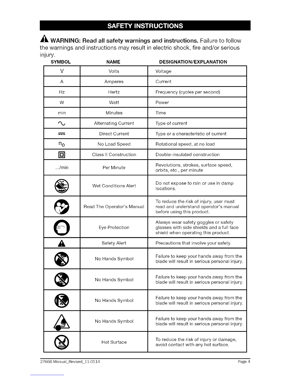
Some of these following symbols may be used on this tool. Please study them
and learn their meaning. Proper interpretation of these symbols will allow you to
operate the tool better and more safely.
27666 ManuaLRevised_11-0114 Page 3

_, WARNING: Read all safety warnings and instructions. Failure to follow
the warnings and instructions may result in electric shock, fire and/or serious
injury.
SYMBOL
v
A
Hz
W
min
n o
[]
_./rain
NAME DESIGNATION/EXPLANATION
Volts Voltage
Amperes Current
Hertz Frequency (cycles per second)
Watt Power
Minutes Time
Alternating Current Type of current
Direct Current Type or a characteristic of current
No Load Speed Rotational speed, at no load
Class II Construction Double-insulated construction
Per Minute Revolutions, strokes, surface speed,
orbits, etc., per minute
Wet Conditions Alert Do not expose to rain or use in damp
locations.
To reduce the risk of injury, user must
Read The Operator's Manual read and understand operator's manual
before using this product.
O Always wear safety goggles or safety
Eye Protection glasses with side shields and a full face
shield when operating this product.
,_ Alert Precautions that involve
Safety your safety.
No Hands Symbol Failure to keep your hands away from theblade will result in serious personal injury.
Failure to keep your hands away from the
No Hands Symbol blade will result in serious personal injury.
Failure to keep your hands away from the
No Hands Symbol blade will result in serious personal injury.
No Hands Symbol Failure to keep your hands away from the
blade will result in serious personal injury.
To reduce the risk of injury or damage,Hot Surface avoid contact with any hot surface.
27666 ManuaLRevised_11-0114 Page 4

GENERAL POWER TOOL SAFETY WARNINGS
_, WARNING: Read all safety warnings and instructions. Failure to follow
the warnings and instructions may result in electric shock, fire and/or serious
personal injury.
• Know your power tool. Read the operator's manual carefully. Learn the
applications, as well as the specific potential hazards related to this tool.
Following this rule will reduce the risk of electric shock, fire or serious injury.
• Save these instructions. Refer to them frequently and use them to instruct
others who may use this tool. if someone borrows this tool, make sure they
have these instructions also.
•The term "power tool" in the warnings refers to your mains-operated
(corded) power tool or battery-operated (cordless) power tool.
READ AND SAVE THESE iNSTRUCTiONS
WORK AREA SAFETY
• Keep the work area clean and well lit. Cluttered or dark areas invite
accidents.
Do not operate power tools in explosive atmospheres, such as in the
presence of flammable liquids, gases or dust. Power tools create sparks
which may ignite the dust or fumes.
Keep children and bystanders away while operating a power tool.
Distractions can cause you to lose control.
ELECTRICAL SAFETY
Power tool plugs must match the outlet. Never modify the plug in
any way. Do not use any adapter plugs with grounded power tools.
Unmodified plugs and matching outlets will reduce risk of electric shock
Avoid body contact with earthed or grounded surfaces such as pipes,
radiators, ranges and refrigerators. There is an increased risk of electric
shock if your body is earthed or grounded.
Do not expose power tools to rain or wet conditions. Water entering a
power tool will increase the risk of electric shock.
inspect the tool cords periodically and, if damaged have them repaired
at your nearest Sears Service Center. Be aware of the cord location.
Do not abuse the cord. Never use the cord for carrying, pulling or unplugging
the power tool. Keep the cord away from heat, oil, sharp edges or moving
parts. Damaged or entangled cords increase the risk of electric shock.
When operating a power tool outdoors, use an extension cord suitable
for outdoor use. Use of a cord suitable for outdoor use reduces the risk of
electric shock.
27666 Manual_Revised_11-0114 Page 5

•if operating apower tool in adamp location is unavoidable, use a
ground fault circuit interrupter (GFCl) protected supply. Use of a GFCI
reduces the risk of electric shock.
PERSONAL SAFETY
Stay alert, watch what you are doing and use common sense when
operating a power tool. Do not use the tool while tired or under the
influence of drugs, alcohol, or medication. A moment of inattention while
operating power tools may result in serious personal injury.
Know your power tool. Read the operator's manual carefully. Learn the
applications, as well as the specific potential hazards related to this tool.
Following this rule will reduce the risk of electric shock, fire or serious injury.
Always wear safety glasses or eye shields when using this router.
Everyday eyeglasses have only impact-resistant lenses; they are not safety
glasses.
Protect your lungs. Wear a face mask or dust mask if the operation is dusty.
Protect your hearing. Wear appropriate personal hearing protection during
use. Under some conditions noise from this product may contribute to
hearing loss.
All visitors and bystanders must wear the same safety equipment that the
operator of the router wears.
Prevent unintentional starting. Ensure that the switch is in the OFF-position
before connecting to a power source and/or battery, picking up or carrying
the tool. Carrying power tools with your finger on the switch or energizing
power tools that have the switch on invites accidents.
Remove any adjusting key or wrench before turning the power tool on.
A wrench or a key left attached to a rotating part of the power tool may result
in personal injury.
Do not overreach. Keep proper footing and balance at all times. This
enables better control of the power tool in unexpected situations.
Dress properly. Do not wear loose clothing or jewelry. Keep your hair,
clothing and gloves away from moving parts. Loose clothes, jewelry or
long hair can be caught in moving parts.
If devices are provided for the connection of dust extraction and
collection facilities, ensure that these are connected and properly used.
Use of these devices can reduce dust-related hazards.
POWER TOOL USE AND CARE
• Do not force the power tool. Use the correct power tool for your
application. The correct power tool will do the job better and more safely at
the rate for which it was designed.
27666 Manual_Revised_11-0114 Page 6

Do not use the power tool if the switch does not turn it on and off. Any
power tool that cannot be controlled with the switch is dangerous and must
be repaired.
Always check the tool for damaged parts before use. Before further
use of the tool, a guard or other part that is damaged should be carefully
checked to determine if it will operate properly and perform its intended
function. Check for misalignment or binding of moving parts, breakage of
parts, and any other condition that may affect the tool's operation. A guard
or other part that is damaged should be properly repaired or replaced at a
Sears Service Center.
Disconnect the plug from the power source and/or the battery from the
power tool before making any adjustments, changing accessories, or
storing power tools. Such preventive safety measures reduce the risk of
starting the power tool accidentally.
• Store idle power tools out of the reach of children and do not allow
persons unfamiliar with the power tool or these instructions to operate
the power tool. Power tools are dangerous in the hands of untrained users.
Maintain power tools. Check for misalignment or binding of moving
parts, breakage of parts and any other condition that may affect the
power tool operation. If damaged, have the power tool repaired before
use. Many accidents are caused by poorly maintained power tools.
• Keep cutting tools sharp and clean. Properly maintained cutting tools with
sharp cutting edges are less likely to bind and are easier to control.
•Use the power tool, accessories, tool bits, etc., in accordance with
these instructions, taking into account the working conditions and the
work to be performed. Use of the power tool for operations different from
those intended could result in a hazardous situation.
,_ WARNING: When using power tools, basic safety precautions should always
be followed to reduce the risk of fire, electric shock, and personal injury.
_1, WARNING: The operation of any tool can result in foreign objects being
propelled into your eyes, resulting in severe eye damage. When operating power
tool, always wear safety goggles or safety glasses with side shields and a full
face shield when needed.
A_, WARNING: If any parts are missing, do not operate the tool until the missing
parts have been replaced. Doing so could result in serious personal injury.
SERVICE SAFETY
• Have your power tool serviced by a qualified repair person using only
identical replacement parts. This will ensure that the safety of the power
tool is maintained.
27666 ManuaLRevised_11-0114 Page 7

If any part of this router is missing or should break, bend, or fail in any
way; or should any electrical component fail to perform properly: shut off
the power switch and remove the plug from the power source and have the
missing, damaged, or failed parts replaced before resuming operation.
Tool service must be performed only at a Sears Parts & Repair Service
Center. Service or maintenance performed by unqualified personnel could
result in a risk of injury.
Use only identical replacement parts when servicing a tool. Follow the
instructions in the maintenance section of this manual. Use of unauthorized
parts or failure to follow maintenance instructions may create a risk of
electric shock or injury.
SPECIFIC SAFETY RULES FOR ROUTER
Hold power tools by insulated gripping surfaces when performing an
operation where the cutting tool may contact hidden wiring or its own cord.
Contact with a "live" wire will make exposed metal parts of the tool" live" and
shock the operator.
Use clamps or another practical way to support and secure the
workpiece to a stable platform. Holding the work by hand or against your
body leaves it unstable and may lead to loss of control.
Maintain a firm grip on the router with both hands to resist starting torque.
Never attempt to use the router motor without first installing it in an
approved base. Failure to heed this warning could result in personal injury
and damage to the motor.
Do not hand-hold the router in an upside down or horizontal position.
The motor can separate from the base if not properly attached according to
the instructions.
Tighten the coliet/nut securely to prevent the cutter bit from slipping. If
the collet/nut is not securely tightened, the cutter bit may detach during use,
causing serious personal injury.
Never tighten the collet/nut without a cutter bit installed in the collet/
nut.
Never hold the piece being cut in your hands or across your legs. It is
important to support and clamp the workpiece properly in order to minimize
body exposure, bit binding, or loss of control.
Always keep the chip shield clean and in place.
Stay alert and clear the router cutter bit path of any obstructions before
starting the motor. Keep cutting area clear of all foreign objects while the
motor is running.
Inspect and remove all nails from lumber before routing.
27666 ManuaLRevised_11-0114 Page 8

Check to see that the cord will not "hang up" during routing operation.
Make sure that the cutter bit is not in contact with the workpiece before
the switch is turned on. The bit must always be running at full speed before
contacting the workpiece.
Keep hands clear of the cutter bit when the motor is running to prevent
personal injury.
Provide clearance under the workpiece for the router cutter bit when
through-cutting.
Keep cutting pressure constant. Do not overload the motor.
Use only sharp cutter bits that are not chipped or cracked. Blunt cutter bits
will cause stalling and burn the workpiece.
Never use this router motor with a cutter bit larger than 34/2 inches in diameter.
Always use cutter bits that are designed for this router. Never use cutter
bits which are larger in diameter than the opening in the router sub-
base. Cutter bits that have cutter diameters larger than the opening could
cause possible loss of control or create other hazardous condition that could
cause serious personal injury.
The sub-base on this router has an opening of 1=1/4 inches. To use cutter
bits with a larger diameter, install and use a sub-base with a larger diameter
opening (sold separately at Sears stores or other Craftsman outlets).
Do not use large router cutter bits for freehand routing. Use of large
cutter bits when freehand routing could cause loss of control or create
hazardous conditions that could result in serious personal injury. If using a
router table, large bits should be used for edging only.
Be sure that the cutter bit is centered in a template guide (sold
separately) prior to template guide applications to avoid personal injury or
damage to finished work.
Do not remove more than 1/8 inch in a single pass. Excessive depth of
cut can result in loss of control that could result in personal injury.
After completing a cut, turn the motor OFF and let it come to complete
stop before removing router from workpiece.
Let the motor come to a complete stop before putting the router down.
Cutter bits coast after power is turned off.
Only use router tables with on=board switch-controlled receptacles.
Failure to use router tables with all the appropriate safety features could
result in serious personal injury.
Disconnect the tool from the power source before making any
adjustments or changing cutter bits.
27666 ManuaLRevised_11-0114 Page 9

•if you are changing a bit immediately after use, be careful not to touch
the collet/nut or cutter bit with your hands or fingers. The heat buildup
from cutting could cause severe burns. Always use the wrench provided.
•Avoid "climb cutting;" see "OPERATION" section in this manual "Climb
cutting" increases the chance for loss of control resulting in possible
_ serious injury._, WARNING: Bits, sockets, and tools get hot during operation.
Wear gloves when touching them.
_1, WARNING: Wear ear protection. Exposure to noise can cause hearing loss.
_, WARNING: To avoid injury, hold the tool by the insulated gripping surfaces
only. If the tool contacts hidden wiring or its own cord, exposed metal parts
of the tool could shock the operator and cause serious injury. Make sure that
hidden electrical wiring, water pipes, or other hazards are not in the cutting path.
WARNING: Your Router should never be connected to the power source
when you are assembling parts, making adjustments, installing or removing bits,
cleaning, or when it is not in use. Disconnecting the router will prevent accidental
starting, which could cause serious personal injury.
When unpacking the box, do not discard any packing materials until all of the
contents are accounted for:
1.
2.
Carefully lift the router out of the carton and place it on a stable, flat surface.
Open the carton to locate the following:
• Vac adapter and 2 screws used to attach it to the base
• Chip shield (already installed on router)
• 1/4-inch .collet/nut (already installed on router)
• 1/2-inch collet/nut
• Collet/nut wrench
• Depth-Adjustment Wrench
• Manual
3. Inspect the items carefully to make sure that no breakage or damage has
occurred during shipping. If any of the items mentioned is missing, (refer to
"PARTS LIST" illustration), return the router to your nearest Sears store to
have the router replaced.
_1, WARNING: If any part is broken or missing, do not attempt to assemble the
router, plug in the power cord, or operate the router until the broken or missing
part is replaced. Failure to do so could result in possible serious injury.
27666 ManuaLRevised_11-0114 Page 10

CARTON CONTENTS (Fig. 1)
®ii Plunge Base Router
Vac adapter
Chip shield (already installed on router)
2 screws (for attaching vac adapter)
1/4-inch Collet/Nut (already installed on router)
1/2-inch Collet/Nut
Depth-Adjustment Wrench
Collet/Nut Wrench
27666 ManuaLRevised_11-0114 Page 11

KNOW YOUR PLUNGE ROUTER (Fig.2)
NOTE: Before attempting to use your router, familiarize yourself with all of the
operating features and safety requirements.
Your plunge base router has a precision-built electric motor and it should only
be connected to a 120-volt, 60-Hz AC only power supply (normal household
current). Do not operate on direct current (DC). This large voltage drop will cause
a loss of power and the motor will overheat. If the router does not operate when
plugged into a correct 120-volt, 60-Hz AC only outlet, check the power supply.
This router has an 8-ft., 2-wire power cord (no adapter needed).
Fig. 1 Motor housing
Super-fine
adjustment knob
Depth indicators
e base
Spindle lock
Depth-rod locking __ Self-releasing
knob Collet/Nut System
Depth rod p shield
Super-fine adj
screw Non-mar sub-base
Depth-stop turret
Key-strip slot
On /Off Toggle Switch
Air vents
"Live Tool Indicator"
Light
8-ft. power Cord
Ergonomic Handles Plunge-depth
locking lever
Quick-release lever Plunge sub-base
Vacuum port
A_, WARNING: Do not allow familiarity with the router to cause a lack of alertness.
A fraction of a second of carelessness is enough to cause severe injury.
27666 ManuaLRevised_11-0114 Page 12

PRODUCT SPECIFICATIONS
Rating 10.0 Amps
No Load Speed 10000-25000 RPM
Peak HP 1-3/4
Input 120-volt, 60Hz AC
Collets/Nuts and Cutter-bit Shank Diameters 1/4 in. and 1/2 in.
Plunge Base Diameter 6-11/16 inches
Sub-Base Opening (Diameter for cutter bit use) 1-1/4 inches
Sub-Base Thickness 1/4 inch
Plunge Base Depth of Cut 2-1/8 inches
_, WARNING: The safe use of this product requires an understanding of the
information on the tool and in this operator's manual, as well as knowledge of
the project you are attempting. Before use of this product, familiarize yourself
with all operating features and safety rules.
This Plunge Router has the following features:
1.
.
3.
4.
5.
8.
7.
8.
9.
Powerful, 10.0 Amp Soft Start Motor develops 1-3/4 Peak HP to handle
most routing jobs.
Variable-Speed Motor runs at 10,000 to 25,000 RPM (no-load speed).
Variable-Speed Dial allows matching proper speed to material and cutter
bit size.
Plunge Base features Fine and Micro Depth Rod Adjustments with Turret
Stops for precise set-ups and repetitive cutting.
Smooth Plunge Action lowers bit into workpiece at 90° for more accurate
cutting.
Protective Plunge Post Bellows protect guideposts from woodchips, dust,
and moisture.
Spindle Lock for easy one-wrench bit changes. Includes 1/4 and 1/2=inch
Self-Releasing Collets/Nuts for use with a wide variety of 1/4-in. and 1/2-in.
router bits, sold separately.
100% Ball Bearings for smooth, efficient operation and long life.
Base Features Large Base Openings and Large Chip Shield, combined
with 3 LED Worklights on Motor to provide high visibility of bit and
workpiece.
10. Durable Non=marring Sub-base glides smoothly over the workpiece. Sub-
base cutter bit opening is 1-1/4 inches. Do not use a bit with a cutter diameter
larger than 1-1/4 inches, as it will not pass through the sub-base opening!
27666 ManuaLRevised_11-0114 Page 13

11. Motor Housing constructed of High Density Nylon and Precision Milled
Cast Aluminum for strength and exact fit into bases.
12. High-impact resistant Motor Housing Top Cap and Handles on Base help
protect tool from damage.
13. Conveniently located ON/OFF toggle switch, side mounted for added
visibility, easy access.
14. Vac adapter allows base to hook up to 1-1/4 inch vac hose attachment, sold
separately.
15. Quick=release edge guide lever for quick installation of and adjustments to
an edge guide (sold separately).
16. "MVE TOOL INDICATOR" light is green when the router is plugged into a
power source. Light is located on motor housing top cap next to power cord
inlet.
17. Replaceable Carbon Brushes (sold separately) for dependable service.
18. Includes carry bag for easy carrying and storage.
NOTE: This tool is shipped completely assembled. To install or remove cutter
bits or add accessories such as vac adapter for hook-up to vacs, see the
following instructions.
SELECTING THE CUTTER BiT
This router comes with 1/4 in. and 1/2 in. collets/nuts that accept 1/4 inch and
1/2 inch shanks, respectively.
_, WARNING: Do not use a router cutter bit that has a cutter bit diameter larger
than 1-1/4 inches with the sub-base that is installed on this router, as it will not
fit through the sub-base opening, will cause damage to the sub-base and the
motor, and could cause serious personal injury to the operator.
NOTE: The sub-base installed on this router has an opening of 1-1/4 inches. To
use cutter bits with larger diameters, use sub-bases with larger openings, sold
separately at Sears stores or other Craftsman outlets.
A_, WARNING: Always turn the motor off and unplug the router before making
any adjustments or installing accessories. Failure to unplug the router could
result in accidental starting, which can cause serious personal injury.
27666 ManuaLRevised_11-0114 Page 14

iNSTALLiNG AND REMOVING THE CUTTER BiT (available separately) (Fig.
3, 4 and 4a)
iNSTALLiNG THE CUTTER BiT
1. Turn the motor off and unplug it from the power source.
2. Remove the motor housing from the base.
NOTE: See the instructions for installing and removing the motor housing from
the plunge base on pages 17 and 18.
3. Set the motor upside down on its top cap, with the collet/nut pointing up.
4. Press the spindle-lock button to engage and lock the spindle shaft and
collet/nut (Fig. 3).
5. Place the wrench on the collet/nut and Fig. 4 /_<_-j,,_ \ Cutters
turn it counterclockwise to loosen the _ X_._' //_
collet/nut slightly so it can accept the __,_..z tl"X _/Bit Shank
cutter bit shank. "J _ Spindle
6. Insert the cutter bit shank into the collet/
nut assembly as far as it will go, then
back the shank out until the cutters are
approximately 1/8 to 1/4 inch away from
the face of the collet/nut. (Fig. 4, 4a)
NOTE: To ensue proper gripping of the cutter Fig. 4a .Cutters
bit shank and minimize run-out, the shank of r-_-_J
the cutter bit must be inserted into the collet/ [_ Collet /
nut at least 5/8 inch.
7. With the cutter bit inserted and spindle-
lock button pressed in to engage the
spindle shaft, place the wrench on collet/
nut and turn clockwise until the collet/nut
is firmly tightened on the cutter bit shank.
_, WARNING: Tighten the collet/nut securely to prevent the cutter bit from
slipping. If the collet/nut is not securely tightened, the cutter bit may detach
during use, causing serious personal injury.
NOTE: To prevent damage to tool, do not tighten the collet/nut without a cutter
bit installed.
REMOVING THE CUTTER BiT
1. Turn the motor off and unplug the router from the power source.
2. Remove the motor from the base.
NOTE: See the instructions for installing and removing the motor housing from
the plunge base on pages 17 and 18.
27666 ManuaLRevised_11-0114 Page 15

3. Set the motor upside down on its top cap, with the collet/nut pointing up.
4. Press the spindle-lock button to engage and lock the spindle shaft and the
collet/nut. (Fig. 3)
5. Place the wrench on the collet/nut and turn it counterclockwise to loosen the
collet/nut slightly; remove cutter bit shank.
COLLET/NUT CARE
Before each use, inspect the collet/nut to make sure that it is clean and that it is
gripping the cutter bit properly.
With the router cutter bit removed, press the spindle lock and turn the collet/nut
counterclockwise until it is free from the motor's spindle shaft.
Blow the collet out with compressed air, and clean the tapered inside of the
collet/nut with a tissue or a fine brush.
_, WARNING: Always wear safety goggles or safety glasses with side shields
during power tool operations or when blowing dust. If the operation is dusty,
also wear a dust mask.
Always make sure that the cutter bit shank, collet/nut and motor spindle are
clean and free of woodchips, dust, residue, grease and rust before installing a
cutter bit or collet/nut.
Apply a slight amount of machine oil to the spindle shaft if it looks dry.
Replace a worn or damaged collet/nut immediately.
NOTE: The collet/nut is self-releasing; it is not necessary to strike the collet/nut
to free the router cutter bit. If the cutter bit seems to be stuck after use, loosen
the collet/nut a little more until it releases.
CUTTER BiTS
For faster, more accurate cutting results, keep cutter bits clean and sharpen only
the inside of the cutting edges. Remove all accumulated pitch and gum from
cutter bits after each use.
When sharpening cutter bits, sharpen only the inside of the cutting edge. Never
grind the outside diameter. Be sure, when sharpening the end of a cutter bit, to
grind so that the clearance angle the same as originally ground.
iNSTALLiNG THE ROUTER MOTOR iN THE BASE (Fig. 5)
_i, WARNING: Never use the router motor without installing it into an approved
base. Failure to do so could result in serious personal injury and damage to
motor.
_l_ WARNING: Always turn the motor off and unplug the router from the power
source before making any adjustments or installing accessories. Failure to turn
the motor off and unplug the router could result in accidental starting, which can
cause serious personal injury.
27666 ManuaLRevised_11-0114 Page 16

1. Fig. 5
2.
3.
4.
Turn the motor off and unplug the router
from the power source.
Place the plunge base on a flat surface.
With the back of the plunge base facing you,
open the motor clamp (A) and make sure
that the plunge action is in the "UP" position
with the plunge lock lever (B) locked.
With the motor housing keystrip-slot (C)
aligned with the plunge base keystrip (D),
lower the motor housing into the plunge
base, engaging the keystrip into the
keystrip-slot.
5. Slide the motor into the base as far as it will go.
B
6. Close the motor clamp securely.
NOTE: When making depth adjustments on the plunge base, the motor clamp
should always be closed securely.
REMOVING THE MOTOR FROM THE BASE (Fig. 5)
_, WARNING: Always turn the motor off and unplug the router from the power
source before making any adjustments or installing accessories. Failure to turn
the motor off and unplug the router could result in accidental starting, which can
cause serious personal injury.
1. Turn the motor off and unplug the router from the power source.
2. Place the router (plunge base and motor housing) on a flat surface.
3. With the back of the plunge base facing you, open the motor clamp (A) and
make sure that the plunge action is in the "UP" position with the plunge lock
lever (B) locked.
4. Lift the motor straight up out of the base, sliding the motor housing
"keystrip-slot" (C) free from the keystrip (D) in the plunge base.
5. Set the motor upside down on its top cap with the collet pointing up and
remove the bit.
_, WARNING: Always remove the cutter bits from the collet/nut when the
router is not being used. Leaving bits installed could result in an accidents
causing serious personal injury.
ADJUSTING THE DEPTH OF CUT
A_, WARNING: Your router should never be turned on or be connected to the
power source when you are assembling parts, making adjustments, installing
or removing collets/nuts and cutter bits, cleaning or when it is not in use.
Disconnecting the router will prevent accidental starting, which could cause
serious personal injury.
27666 ManuaLRevised_11-0114 Page 17

PLUNGING ACTION (Fig. 5a)
The plunge base feature simplifies depth
adjustments and allows the cutter bit to be
accurately lowered into the workpiece for
precise set-ups.
1.
2.
3.
To lower the cutter bit, release the plunge-
lock lever by moving it "UP" to the unlocked
position.
Apply an even, downward pressure on the
plunge action until the cutter bit reaches the
desired depth, then move the plunge-lock
lever "DOWN" to the locked position.
Fig. 5a
Guide Slot Cutting
To raise the bit and the plunge action,
unlock the plunge-lock lever and the cutter bit and the plunge action will
automatically retract from the workpiece and return to the raised position.
Always have the plunge action in the raised position and locked when the bit is
not cutting in the workpiece.
DEPTH-STOP ROD AND DEPTH-STOP TURRET (Fig. 6)
Control the cutting depth with the depth=stop rod and the depth=stop turret
as follows:
1.
2.
3.
4.
5.
Turn the motor off and unplug the router from the power source.
Place the router on a flat, level surface.
With the cutter bit already installed, lower
the plunge action until the cutter bit makes
contact with the flat, level surface on which
the router is sitting.
Lock the plunge depth locking lever (F).
This position is "0" from which further depth
adjustments can be made.
To set a desired depth-of-cut, rotate the
depth-stop turret until the lowest step of
the turret (A) is aligned directly under the
Depth-Stop Rod (B). Loosen the Depth Rod
Locking Knob and lower the depth-stop
rod until it contacts the lowest step on the
turret.
Fig. 6F
C
B
A
6. Slide the Clear Plastic Depth-Indicator (D) until the red line on the indicator is
lined up with "0", marked in black on the bottom of the depth scale. (This is
now indicating the point at which the bit makes contact with the workpiece).
27666 ManuaLRevised_11-0114 Page 18

7.
8.
g.
To set the cutting depth, slide the Depth-Stop Rod up until the red line on
the clear plastic depth-indicator points to the desired cutting depth on the
Depth Scale (E). Secure the Depth-Stop Rod at this position by tightening
the Depth Rod Locking Knob.
Unlock the Plunge-Lock Lever (F) to allow the bit to automatically retract to
the UP position.
The desired depth-of-cut may now be achieved by plunging the router down
until the depth-stop rod contacts the selected step on the depth-stop turret.
NOTE: When making depth adjustments on the plunge base, the motor clamp
should always be closed securely.
Making Deep Cuts with the Depth=Stop Turret (Fig. 7}
NOTE: Making a single deep cut is never advisable. Smaller diameter cutter bits
are easily broken by too much side thrust and torque. Larger cutter bits will cause a
rough cut and be difficult to guide and control. For
these reasons, do not exceed 1/8-in. depth of cut
in a single pass.
To produce deep cuts, always make several
progressively deeper cuts, starting with the
highest step on the depth-stop turret and, after
each cut, rotating the turret to the next lowest
step until the Lowest or Last step is reached.
Each of the 4 steps progresses by 1/4-inch
increments. The 4 steps represent a total of "0"-in.
to 3/4 in. with a full 360 ° rotation of the turret.
Repeat this process if necessary.
Micro Adjustments with the Depth=Stop Rod
and Depth=Stop Turret
Fig. 7
f
A
B
C
The Depth-Stop Rod has a Micro Adjustment Knob (A) that turns a screw (B)
(inside the rod) either clockwise or counterclockwise (lowering or raising) the
depth-stop rod on the turret (C} for micro-fine adjustments of the plunge depth.
Each complete revolution of the Micro Adjustment Knob adjusts the plunging
depth by 3/64 inch.
A reference indicator line is embossed into the Depth-Stop Rod under the fine-
adjustment knob to set "0".
When micro-adjusting the plunge depth, before setting the Depth-Stop Rod and
Depth-Stop turret, always make sure that the micro adjustment screw has been
turned down (clockwise) several revolutions from its top, or starting position, so
it can be adjusted upward.
Always set your micro adjustments with the plunge action in the raised, (or up)
position, and locked down.
27666 ManuaLRevised_11-0114 Page 19

To use the micro adjustment knob once the depth rod and turret have been set,
check the final depth setting and micro adjust as follows:
• To micro-increase the plunge depth, turn the knob counterclockwise to raise
the micro adjustment screw,
To micro-reduce the plunge depth, turn the knob clockwise to lower the
micro adjustment screw.
TOGGLE "ON/OFF" SWITCH (Fig. 8)
Use the toggle switch located on the top cap of the motor housing to turn the
router "ON" and "OFF".
The left side of the toggle switch hood (as you
face it) is marked "l" for "On" and the right Fig. 8
side (as you face it) is marked "0" for "Off".
To turn the motor "ON", push the toggle
switch to the left side marked "l", or "On"
To turn the motor "OFF" push the toggle
switch to the right side marked "0", or "Off".
Contact the workpiece with the router and
cutter bit only after the router has reached full
speed slected. Turn the router motor "OFF"
and allow the cutter bit to come to a complete
stop before removing the router and cutter bit from the workpiece.
SOFT START FEATURE
Soft Start minimizes torque twist, which is customary in larger router motors, by
limiting the speed at which the motor starts. This increases the motor's life.
ELECTRONIC FEEDBACK CONTROL
The electronic feedback control maintains a constant speed under load to
provide a smooth finish.
LED WORKLIGHTS (Fig. 9)
Your router motor has 3 built-in worklights
located around the collet/nut to provide high
visibility of the workpiece during operation.
These lights are always "On" when the toggle
switch is in the "On "position.
Fig. 9
i;i
27666 ManuaLRevised_11-0114 Page 20
Table of contents
Other Craftsman Wood Router manuals

Craftsman
Craftsman 315.175040 User manual

Craftsman
Craftsman DeWalt 625 User manual

Craftsman
Craftsman 171.24874 User manual

Craftsman
Craftsman 315.269211 User manual

Craftsman
Craftsman 720.25251 User manual

Craftsman
Craftsman IB-28140 User manual

Craftsman
Craftsman 315.175140 User manual

Craftsman
Craftsman 315.175111 User manual