SHOR-LINE Oxygen Therapy Plus Door User manual

Save This Guide For Future Reference
PN: 006.9140.20 January 2019
Oxygen Therapy Plus Door
ASSEMBLY GUIDE
Oxygen Therapy Plus Door
(30x30 Door Conguration Shown)
(Cage NOT Included)

Shor-Line.com
ii
INTRODUCTION
Introduction
Thank you for purchasing Shor-Line products. As a leader in animal care equipment, our
commitment to provide quality products and personable customer service is the same as it
was in 1927.
This Guide provides information regarding the installation, use, and care of your Shor-Line
product. Keep this Guide in a safe and convenient place for reference.
For further questions, to purchase additional products, or to replace a lost or damaged
Guide, please feel free to contact Shor-Line:
SHOR-LINE
Schroer Manufacturing Company
511 Osage Ave.
Kansas City, Kansas 66105, USA
PHONE: 800.444.1579
LOCAL: 913.281.1500
FAX: 913.281.5339
EMAIL: [email protected]
WEB ADDRESS: SHOR-LINE.com
SHOR-LINE LIMITED
Vale Business Park Llandow,
Vale of Glamorgan CF71 7PF
United Kingdom
PHONE: +44 1446 77 20 41
FAX: +44 1446 77 36 68
EMAIL: [email protected]
WEB ADDRESS: SHOR-LINE.co.uk
Shor-Line may provide instructions that supplement or supersede this Guide at any time.
Contact Shor-Line to ensure the Guide is the latest version.
During installation, if a contradiction between this Guide, existing conditions, or local
regulations arise, contact a Shor-Line representative before proceeding with installation.
Visit Shor-line.com for a full list of TERMS AND CONDITIONS.
© Copyright 2019 Schroer Manufacturing Company. All rights reserved.
READ THIS GUIDE COMPLETELY BEFORE INSTALLATION AND USE AND
THOROUGHLY UNDERSTAND AND FOLLOW ALL SAFETY INSTRUCTIONS.
WEAR PERSONAL PROTECTIVE EQUIPMENT, such as, but not limited to, eye
protection, back support brace, and gloves during installation. Failure to do so could
result in SERIOUS INJURY.
This product is intended to be used for animals only. Do not use for anything other than
the intended purpose.
INTRODUCTION

iii
Shor-Line.com
INTRODUCTION
Introduction .................................................................................................... ii
GENERAL INFORMATION
General information........................................................................................1
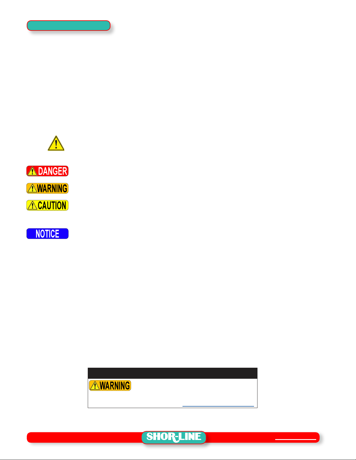
Safety Alert Symbol ............................................................................................................ 1
Personal Protective Equipment (PPE)................................................................................ 1
Safety Warnings Included In This Guide ............................................................................ 2
SECTION ONE, PRE-ASSEMBLY
Shipment Inventory And Inspection................................................................3
.................................................... 3
Oxygen Therapy Plus Door - Double Door Conversion Kit ................................................ 3
Shipment Inventory............................................................................................................. 3
Shipment Inspection ........................................................................................................... 3
Damage Reporting ............................................................................................................. 4
Oxygen Therapy Plus Door Sizes ...................................................................................... 4
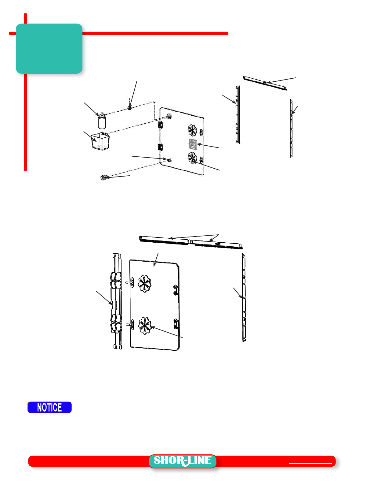
Component Parts List ......................................................................................................... 5
Hardware Parts List ............................................................................................................ 6
SECTION TWO, ASSEMBLY PROCEDURES
Assembly Procedures ....................................................................................7
........................................................................ 7
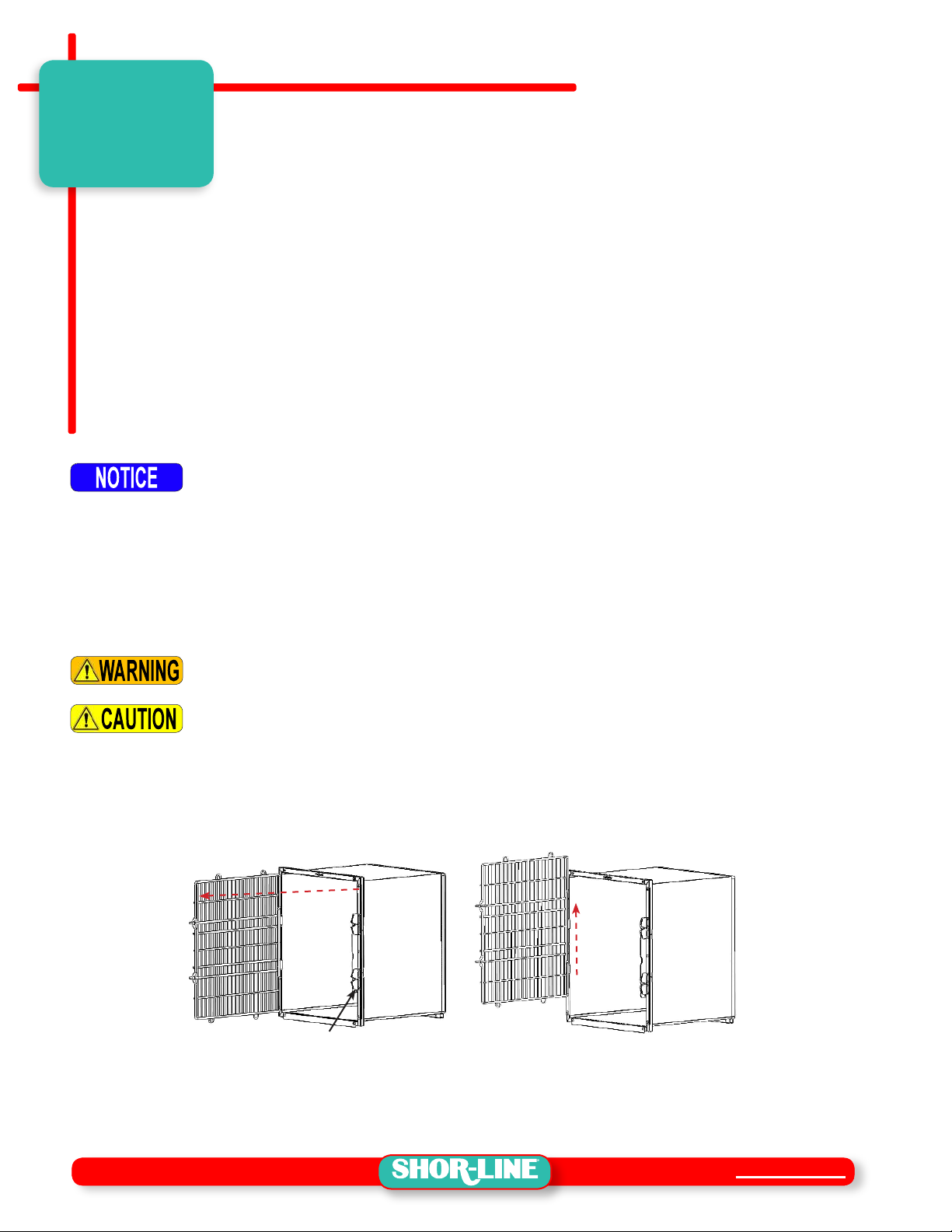
Cage Door Removal - Single Door ..................................................................................... 7
Cage Door Removal - Double Door.................................................................................... 8
Double Door Latch Bar Removal .................................................................................. 8
Oxygen Therapy Plus Door Installation ............................................................................ 10
Oxygen Therapy Plus Door Installation - Double Door......................................................11
SECTION THREE, USE AND CARE
Oxygen Therapy Plus Door Use And Care ..................................................13
Safe Use Practices ........................................................................................................... 13
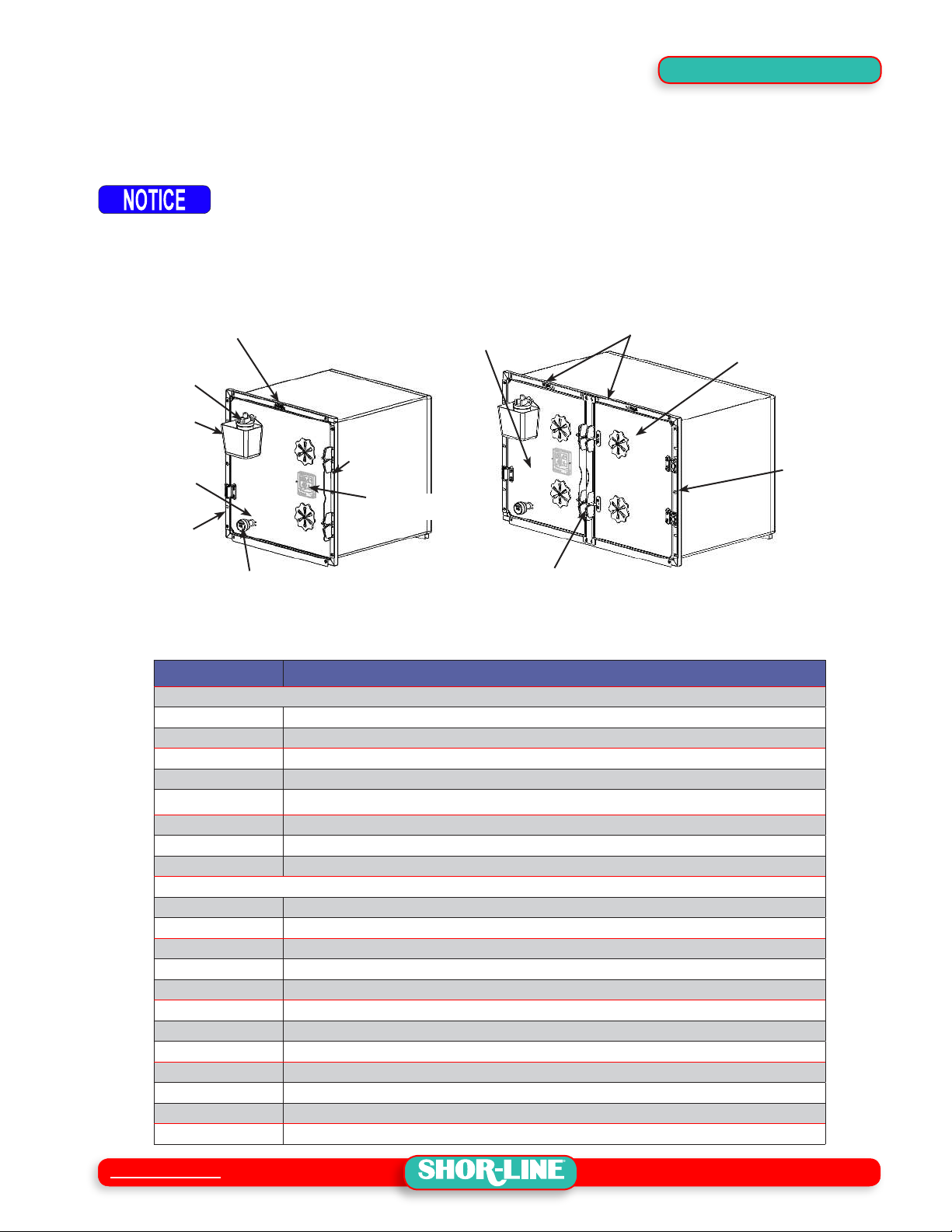
Component Instructions.................................................................................................... 13
.................................................................................................................... 13
Oxygen Analyzer......................................................................................................... 14
Thermometer/Hygrometer .......................................................................................... 15
Adjustable Vents ......................................................................................................... 15
Reversing Cage Door Swing ............................................................................................ 15
Cage Hardware........................................................................................................... 15
Door Rotation/Component Relocation ........................................................................ 17
Hinge Bushing Procedures ......................................................................................... 19
General Maintenance & Care ........................................................................................... 20
Maintenance Recommendations ................................................................................ 20
Care Recommendations ............................................................................................ 20
SECTION FOUR, TERMS & CONDITIONS
Terms And Conditions ..................................................................................21
Damaged Freight Procedures .......................................................................................... 21
Limited Warranty ........................................................................................22
Contact Information......................................................................................23
CONTENTS

Shor-Line.com
1
GENERAL INFORMATION
General information
Refer to the Guide, images and content to assist with the installation of the product.
Throughout the Guide, safety notices provide help for a successful installation.
The Oxygen Therapy Plus Door is also referred to as the "O
SAFETY FIRST!
Shor-Line uses the following symbols and signal words to identify potential hazards or
unsafe practices:
Safety Alert Symbol
Indicates a potential personal injury hazard exists. It is important to heed any
safety warning information associated with this alert symbol.
Signal Words for Hazard Alerting Safety Messages
Indicates a hazardous situation which, if not avoided, WILL result in serious injury
or death.
Indicates a hazardous situation which, if not avoided, COULD result in serious injury
or death.
Indicates a hazardous situation which, if not avoided, COULD result in minor or
moderate injury.
Important Information Symbol
Indicates information considered important but not directly hazard related.
Personal Protective Equipment (PPE)
PPE refers to protective clothing or other equipment designed to protect against injury. It
is the responsibility of the client/installer to ensure all local and federal codes are adhered
to during the installation and assembly of this product. Included is a list of PPE items
suggested, but not limited to, protective equipment to help complete the installation safely.
• Eye protection • Gloves
• Metatarsal, foot protection • Back Support Brace
Shor-Line makes no guarantee, implied or otherwise, that the information included in
this Guide will be complete or failsafe, or that the information will prevent an injury from
need to be taken in any given emergency instance.
California Proposition 65 Warning
This product can expose you to chemicals
including chromium, which are known to the
state of California to cause cancer. For more
information go to: www.P65Warnings.ca.gov
SAFETY

2
Shor-Line.com
Safety Warnings Included In This Guide
READ THIS GUIDE COMPLETELY BEFORE INSTALLATION AND USE AND
THOROUGHLY UNDERSTAND AND FOLLOW ALL SAFETY INSTRUCTIONS.
WEAR PERSONAL PROTECTIVE EQUIPMENT (PPE), such as, but not limited to, eye
protection, protective gloves and Metatarsal/foot protection during installation. Failure
to do so could result in SERIOUS INJURY.
Enlist help and USE SAFE LIFTING PRACTICES during assembly, installation and
moving equipment.
Oxygen Therapy Plus Doors and Stainless Steel Cages have sharp edges, stay clear
of and DO NOT TOUCH exposed edges which, if not avoided, could result in SERIOUS
INJURY OR DEATH.
This product is intended to be used for animals only. Do not use for anything other than
the intended purpose.
Keep hands clear of possible pinch areas when assembling parts, which if not avoided,
could result in MINOR to MODERATE INJURY.
Keep hands, ngers and patients limbs clear of possible pinch areas when adjusting
the vents, which if not avoided, could result in MINOR to MODERATE INJURY.
SAFETY

Shor-Line.com
3
SECTION ONE, PRE-ASSEMBLY
Shipment Inventory And Inspection
Oxygen Therapy Plus Door - Single Door Conguration
FIGURE 1.1 - Typical Oxygen Therapy Plus Door - Single Door Conguration
HUMIDIFIER
CONTAINER
JAMB SEAL
HEAD SEAL
OXYGEN SENSOR
(SOLD SEPARATELY)
JAMB SEAL
HUMIDIFIER ADAPTER
W/LOCK SCREW
ADJUSTABLE VENTS
HYGROMETER-
THERMOMETER
DOOR PLUG
Oxygen Therapy Plus Door - Double Door Conversion Kit
The Double Door Conversion Kit is the sum of the parts required to convert a Single Therapy
FIGURE 1.2 - Typical Oxygen Therapy Plus Door - Double Door Conversion Kit
JAMB SEAL
HEAD SEAL
ADJUSTABLE VENTS
LATCH BAR
W/SEALS
CONVERSION
DOOR
Shipment Inventory
At arrival, unpack and inspect the shipment to ensure it is complete and free of damages
that may have occurred during shipping. Compare the packing list with the shipment to
ensure all parts/components have been received in good condition. See FIGURES 1.1-1.5
Avoid using razor blade or cutting devices, product surfaces scratch easily.
Shipment Inspection
While verifying the shipment contents, take a moment to inspect each component for
damage. This should be done before the shipment is signed received and accepted. If
damaged components are apparent, follow the claim procedures set forth by the carrier.
SECTION
ONE

4
Shor-Line.com
Damage Reporting
Follow the instructions within Shor-Line’s Damage and Freight Procedures. Contact
Shor-Line (800.444.1579) immediately to expedite the process.
After fteen (15) calendar days of receipt of merchandise, policies become void.
Oxygen Therapy Plus Door Sizes
door (SD) or double door (DD) cage applications to best serve a variety of space conditions
and facility requirements. Refer to FIGURE 1.3
FIGURE 1.3 - Oxygen Therapy Plus Door (30x30" SD & 48x30" DD Shown)
HEAD SEAL
OXYGEN SENSOR
(SOLD SEPARATELY)
HEAD SEAL
JAMB SEAL
02 DOOR
W/COMPONENTS
HYGROMETER-
THERMOMETER
JAMB SEAL
DOOR PLUG
(STANDARD)
HUMIDIFIER
JAMB SEAL
DD CONVERSION
LATCH BAR
CONTAINER
NOTE: STAINLESS STEEL
CAGES NOT INCLUDED
CONVERSION
DOOR
Part # Description
Single Door Conversion Kit:
914.2424.20 DOOR,24X24,OXYGEN THERAPY PLUS
914.2430.20 DOOR,24X30,OXYGEN THERAPY PLUS
914.2436.20 DOOR,24X36,OXYGEN THERAPY PLUS
914.3030.20 DOOR,30X30,OXYGEN THERAPY PLUS
914.3036.20 DOOR,30X36,OXYGEN THERAPY PLUS
914.3624.20 DOOR,36X24,OXYGEN THERAPY PLUS
914.3630.20 DOOR,36X30,OXYGEN THERAPY PLUS
914.3636.20 DOOR,36X36,OXYGEN THERAPY PLUS
Double Door Conversion Kit:
914.2430.21 DOOR,24X30,O2 CONVERSION
• 301.0220.09 • DOOR,24 X 30 GLASS CONVERSION,TYPE 4
• 300.2384.00 • BRACKET,DD,TOP,LH,24 IN,O2 DOOR PLUS
• 300.2385.00 • BRACKET,DD,TOP,RH,24 IN,O2 DOOR PLUS
• 714.0008.00 • ASSY,30 IN DD CHANNEL,O2 DOOR PLUS
• 300.2302.00 • BRACKET,SIDE,30 IN,O2 DOOR PLUS
914.2436.21 DOOR,24X36,O2 CONVERSION
• 301.0220.10 • DOOR,24 X 36 GLASS CONVERSION,TYPE 4
• 300.2384.00 • BRACKET,DD,TOP,LH,24 IN,O2 DOOR PLUS
• 300.2385.00 • BRACKET,DD,TOP,RH,24 IN,O2 DOOR PLUS
• 714.0009.00 • ASSY,36 IN DD CHANNEL,O2 DOOR PLUS
• 300.2302.00 • BRACKET,SIDE,30 IN,O2 DOOR PLUS
SECTION ONE

Shor-Line.com
5
SECTION ONE
Component Parts List
FIGURE 1.4 - Oxygen Therapy Plus Door (30x30" Shown)
01
05
02
14
03
06
10 07
04
08 11
09
16
17 19
20
12
18
15 13
Item Part # Description Qty
01 NOTE 1 DOOR,GLASS WITH VENTS,TYPE 4 1
02 NOTE 1 BRACKET,SIDE,O2 DOOR PLUS (Jamb Seal) 2
03 NOTE 1 BRACKET,TOP,O2 DOOR PLUS (Head Seal) 1
04 • 182.0009.00 • SEAL,.360X.5D W-H2 38 EPDM Per Foot
05 025.0004.00 HUMIDIFIER (3 ea. initial shipment) Replacements Sold Separately 1
06 301.0207.01 CONTAINER PLASTIC,O2 DOOR 1
07 • 310.0206.00 • ALUMINUM BRACKET 1
08 • 310.1181.00 • WASHER,O2 DOOR,ALUMINUM 1
09 • 310.0209.00 • ADAPTER,HUMIDIFIER 1
10 • 061.1008.01 • #10-32X.875 RD HD PHILLIPS SS 2
11 • 063.1000.00 • #10-32 HX NUT NYLOCK SS 2
12 195.1377.00 O2 ANALYZER,OXYGEN THERAPY PLUS (SOLD SEPARATELY) 1
13 • 300.2315.00 • HOLE PLUG MALE,O2 DOOR 1
14 • 300.2314.00 • HOLE PLUG,FEMALE,O2 DOOR 1
15 • 062.2507.03 • .250-20 X .750 FLAT HD PHL SS 1
16 025.0005.00 HYGROMETER-THERMOMETER-BIG DIGIT 1
17 • 714.0000.18 • WELDMENT,BRKT,HYGRO-THERMO 1
18 • 062.0607.01 • #6-32X.750 RD HD PHL SS 2
19 • 065.0600.10 • #6 SPLIT LOCK WASHER, PLTD 2
20 • 064.0600.10 • #6-32 ACORN NUT SAE HI-CROWN SS 2
21 300.2309.00 • COVER,02 ANALYZER,TP 4 DOOR 1
NOTE 1 - Sizes vary, contact Shor-Line Technical Service Department to verify cage sizes (1.800.444.1579)
21

6
Shor-Line.com
Hardware Parts List
FIGURE 1.5 - Oxygen Therapy Plus Door Hardware
01
10
11
06
07
14
15
12 09
15 13
08
05
16
02
04 03
Item Part # Description Qty
01 NOTE 1 DOOR,GLASS WITH VENTS,TYPE 4 1
02 714.0001.00 WELDMNT,HINGE TYPE 4 2
03 • 181.0063.00 • BUSHING, HINGE, MALE, KENNEL, TYPE 3 2
04 • 181.0063.01 • BUSHING, HINGE, FEMALE, KENNEL, TYPE 3 2
05 714.0001.00 DOOR HINGE POST 2
06 • 062.2510.05 • .250-20 X 1.000 TRUSS HD PHIL SS 4
07 • 065.2500.00 • .250 FL WASH SAE SS 4
08 • 064.2500.02 • .250-20 HX NUT NYLOCK SS 4
09 714.0002.00 WLDMNT,LATCH PIN,TYPE 4 DOOR 2
10 • 062.2510.05 • .250-20 X 1.000 TRUSS HD PHIL SS 4
11 • 065.2500.00 • .250 FL WASH SAE SS 4
12 • 064.2500.02 • .250-20 HX NUT NYLOCK SS 4
13 301.0220.11 DOOR,VENT COVER,TYPE 4 2
14 • 062.2510.05 • .250-20 X 1.000 TRUSS HD PHIL SS 2
15 • 065.2500.00 • .250 FL WASH SAE SS 4
16 • 064.2500.02 • .250-20 HX NUT NYLOCK SS 2
NOTE 1 - Sizes vary, contact Shor-Line Technical Service Department to verify cage sizes (1.800.444.1579)
SECTION ONE

Shor-Line.com
7
SECTION TWO, ASSEMBLY PROCEDURES
Assembly Procedures
Oxygen Therapy Plus Door Congurations
Oxygen Therapy Plus Door (ODoor) is available in several sizes. The doors are designed
to be installed onto existing (sold separately) stainless steel cages. Verify the width and
height of the cage with the dimensions of the ODoor to be installed.
The OO
Door can be used with some older model Type II hinge cages. Contact Shor-Line Technical
Service department to verify cage door types and compatibility (1.800.444.1579).
A second door equipped with vents only is used in combination with an ODoor when
converting a 48" wide cage to a double door oxygen therapy cage. Double door cages
share a latch bar centered between the doors. The door hardware and components can be
reoriented to either locate the O
Do NOT use power tools for any procedures listed in this manual. Doing so can scratch
product surfaces and/or cause hardware to fail. Do NOT over-tighten hardware.
Cage Door Removal - Single Door
Door hinges may vary depending on the cage model used for the Oxygen Therapy Plus
removal procedures and hardware requirements for older model cages.
If equipped, lock all casters on mobile cage banks to prevent movement during the
installation procedures.
Enlist help and USE SAFE LIFTING PRACTICES during assembly, installation and
moving equipment.
Keep hands clear of possible pinch areas when assembling parts, which if not avoided,
could result in MINOR to MODERATE INJURY.
STEP 1: Slide the latch bar up and swing the door to the open position (90°to cage face).
See FIGURE 2.1
STEP 2: Lift the door upward, sliding the bushings out of the hinge assemblies. Set away
from the assembly area. See FIGURE 2.2
FIGURE 2.1 - Open Door 90°
UP TO RELEASE LATCH
SWING DOOR
90 DEGREES
FIGURE 2.2 - Door Removal
SLIDE DOOR UP
OUT OF HINGES
STEP 3: Clean and store unused grill doors and hardware for future re-installation,
if needed.
SECTION
TWO

8
Shor-Line.com
Cage Door Removal - Double Door
Door hinges may vary depending on the release model of the cages. Type III cages
are used for this procedure. Contact Shor-Line for door removal procedures for older
model cages.
STEP 1: Slide the latch bar up and swing the door to the open position (90°to cage face).
See FIGURE 2.3
STEP 2: Lift the door up, sliding the bushings out of the hinge assembly. Set away from the
assembly area. See FIGURE 2.4
FIGURE 2.3 - Open Door
UP TO RELEASE LATCH
SWING DOOR
90 DEGREES
FIGURE 2.4 - Door Removal
SLIDE DOOR UP
OUT OF HINGES
Enlist help and USE SAFE LIFTING PRACTICES during assembly, installation and
moving equipment.
Keep hands clear of possible pinch areas when assembling parts, which if not avoided,
could result in MINOR to MODERATE INJURY.
STEP 3: Repeat Steps 1 and 2 to remove the second door.
STEP 4: Clean and store unused grill doors and hardware for future re-installation,
if needed.
Double Door Latch Bar Removal
Shor-Line's double door cage share a latch bar that can
be easily removed for greater access when transferring
a patient into or out of the cage comfortably.
The latch bar is also used for the divider panel. The
larger, double door cages can be split into two cages
by inserting the divider panel. Divider panels are sold
separately, contact Shor-Line for size availability.
To convert a double door cage to an Oxygen Therapy
cage, the latch bar must be replaced with the latch bar
which include jamb seal strips.
The O2Door latch bar is NOT equipped with a center divider slot. Center dividers do not
seal the cage space. Store center dividers with the removed grill doors and center latch
bar assembly for future use.
FIGURE 2.5 - Center Latch w/Divider
SECTION TWO

Shor-Line.com
9
SECTION TWO
STEP 1: Open or remove both doors if not already done so.
The latch bar has keyed (hole with a smaller slot) top holes. And the bottom of the
latch bar uses open end slots, enabling the bar to be slid out from behind the latch bar
retaining pins. See FIGURE 2.6
FIGURE 2.6 - Standard Double Door Latch Bar
CENTER LATCH BAR
KEYHOLE SLOT
OPEN END
SLOT
STEP 2: Lift the latch bar upward to clear the keyhole slots located at the top of the latch
bar. See FIGURE 2.7
FIGURE 2.7 - Latch Top Keyhole Slot
SLIDE UP
FIGURE 2.8 - Remove Latch Top
REMOVE FROM
LATCH PINS
STEP 3: Once clear of the keyhole slot, pull the top of the latch bar clear of the latch upper
pins. See FIGURE 2.8
STEP 4: Lift the latch bar upward to clear the
latch pins located at the bottom. The
bottom of the latch bar has open end
slots at the end of the bar to easily slide
out from behind the latch lower pins.
See FIGURE 2.9
FIGURE 2.9 - Remove Latch Bottom
SLIDE OUT

10
Shor-Line.com
Oxygen Therapy Plus Door Installation
The ODoor and components are packaged in
separate boxes. Unpack and organize the door
components for assembly and installation.
Enlist help and USE SAFE LIFTING
PRACTICES during assembly, installation and
moving equipment.
Keep hands clear of possible pinch areas when
assembling parts, which if not avoided, could
result in MINOR to MODERATE INJURY.
STEP 1: Loosen trim plates, hinges, latch bar and trim strips. Do NOT remove screws or
hardware. See FIGURE 2.10
STEP 2: Align the slots on the jamb seal (side) with the hardware screws. Slide the jamb
seal under the trim plates, strips and hardware. Secure the jamb seal with the
center screw, do NOT fully tighten. See FIGURE 2.11
STEP 3: Repeat STEP 2 for opposite side jamb seal.
STEP 4: Align the slots on the head seal (top) with the hardware screws. Slide the head
seal under the trim plates. Secure the head seal by tightening the top trim plate
screws. See FIGURE 2.12
FIGURE 2.11 - Jamb Seal Installation FIGURE 2.12 - Head Seal Installation
STEP 5: Tighten all trim plates, strips and hardware to secure the jamb and head seals
in place.
STEP 6: Install the ODoor by holding the door hinge pins/bushings above the cage
hinges at a 90°angle to the face of the cage. Slide the hinge pins/bushings down
into the hinges. See FIGURE 2.13
The hinge bushings have a at side that slide
through the opening in the hinge assembly. The
at side of the bushings must be facing away
from the cage to align with the hinges. The
hinge bushing must fully seat into the hinge for
proper operation.
STEP 7: Close the door, check latch operation and
adjust alignment to ensure the ODoor
latches correctly.
FIGURE 2.10 - Loosen Trim
LOOSEN, DO NOT REMOVE
FIGURE 2.13 - Door Installation
PERPENDICULAR TO CAGE FACE
SECTION TWO

Shor-Line.com
11
SECTION TWO
Oxygen Therapy Plus Door Installation - Double Door
The O
separate boxes. Unpack and organize the door
components for assembly and installation.
If equipped, lock all casters on mobile cage banks to
prevent movement during the installation procedures.
Enlist help and USE SAFE LIFTING
PRACTICES during assembly, installation and
moving equipment.
Keep hands clear of possible pinch areas when
assembling parts, which if not avoided, could
result in MINOR to MODERATE INJURY.
STEP 1: Loosen trim plates, hinges and trim strips. Do NOT remove screws or hardware.
See FIGURE 2.14
STEP 2: Align the slots on the jamb seal (side) with the hardware screws. Slide the jamb
seal under the trim plates, strips and hardware. Secure the jamb seal with the
center screw, do NOT fully tighten. See FIGURE 2.15
STEP 3: Repeat STEP 2 for the opposite side jamb seal. See FIGURE 2.16
FIGURE 2.15 - Left Jamb Seal Installation FIGURE 2.16 - Right Jamb Seal Installation
STEP 4: Align the slots on the head seal (top) with the hardware screws. Slide the head
seal under the trim plates. Secure the head seal by tightening the top trim plate
screws. Do NOT fully tighten. See FIGURE 2.17
STEP 5: Tighten all trim plates, strips and hardware to secure the jamb and head seals
in place. See FIGURE 2.18
FIGURE 2.17 - Left Head Seal Installation FIGURE 2.18 - Right Head Seal Installation
FIGURE 2.14 - Loosen Hardware
LOOSEN, DO NOT FULLY
REMOVE SCREWS/TRIM

12
Shor-Line.com
STEP 6: The double door conversion kit includes a
latch bar equipped with jamb seals. Follow
the latch bar removal procedures (reverse
order) to install the new latch bar assembly.
See FIGURE 2.19
Ensure the slots in the end of the latch bar are
located on the bottom of the cage.
STEP 7: Install the ODoor by holding the door hinge
pins/bushings above the cage hinges at a
90° angle to the face of the cage. Slide the
hinge pins/bushings down into the hinges.
See FIGURE 2.20
The hinge bushings have a at side that slide through the opening in the hinge
assembly. The at side of the bushings must be facing away from the cage to align with
the hinges. The hinge bushing must fully seat into the hinge for proper operation.
STEP 8: Repeat STEP 7 to install the conversion door on the right-hand side of the cage.
See FIGURE 2.21
FIGURE 2.20 - Door Installation FIGURE 2.21 - Door Installation
STEP 9: Close the doors, check latch operation and adjust alignment to ensure the O
Doors latch correctly.
FIGURE 2.22 - 48" Wide Oxygen Therapy Plus Conguration (Options Vary)
FIGURE 2.19 - Latch Bar Installation
SECTION TWO

Shor-Line.com
13
SECTION THREE, USE AND CARE
Oxygen Therapy Plus Door Use And Care
Safe Use Practices
Always use safe practices during loading and unloading patients from cages. All procedures
for cage use should be created by the facility owner and followed by all users. Common
sense and being aware of safety concerns should always drive procedures. Below is a list of
recommendations and situational conditions that require attention, heed all warnings.
• Do NOT move a cage while occupied with animals.
• Do NOT force the cage door closed. Verify alignment issues and correct as required.
• Do NOT move cages with the doors in the open position.
Component Instructions
Verify which components match the order and proceed to the components/accessories
sections required to complete the installation.
Do NOT use powered tools for any procedures listed in this manual. Doing so can
scratch product surfaces and/or cause hardware to fail.
FIGURE 3.1 - Oxygen Therapy Plus Door (30x30" SD & 48x30" DD Shown)
SINGLE DOOR
CONFIGURATION
DOUBLE DOOR
CONFIGURATION
NOTE: STAINLESS STEEL
CAGES NOT INCLUDED
OXYGEN SENSOR
(SOLD SEPARATELY)
OXYGEN SENSOR
(SOLD SEPARATELY)
Enlist help and USE SAFE LIFTING PRACTICES during assembly, installation and
moving equipment.
Keep hands clear of possible pinch areas when assembling parts, which if not avoided,
could result in MINOR to MODERATE INJURY.
Keep hands, ngers and patients limbs clear of possible pinch areas when adjusting
the vents, which if not avoided, could result in MINOR to MODERATE INJURY.
Humidier
is provided which holds either cold (ice) or warm water to control the temperature of the
connector to the source oxygen line that can be secured into the adapter.
THREE
SECTION

14
Shor-Line.com
Three are included with the initial shipment of the ODoor.
FIGURE 3.2 - Humidier
ALUMINUM
BRACKET
HUMIDIFIER
CONTAINER
FIGURE 3.3 - Oxygen Analyzer
ALUMINUM
BRACKET
HUMIDIFIER
ADAPTER
HUMIDIFIER
HUMIDIFIER
CONTAINER
STEP 1:
See FIGURE 3.2
STEP 2:
Refer to the manufacturer's operation, Safety warnings and maintenance procedures.
Oxygen Analyzer
The oxygen analyzer is an optional component for the ODoor, sold separately. The
oxygen analyzer can be used to spot check oxygen concentration within the Otherapy
treatment cage.
Refer to the manufacturer's operation, calibration and maintenance procedures
for instruction.
STEP 1: Install the OAnalyzer by removing the plug assembly with a Phillips head
screwdriver. Clean and store the plug for replacement into the door when the
analyzer is not used. See FIGURE 3.4
STEP 2: Insert the analyzer through the hole and secure with the cover, thread onto the
analyzer, hand tighten. See FIGURE 3.5
FIGURE 3.4 - O2Analyzer Plug Removal
REMOVE
PLUG
ASSEMBLY
FIGURE 3.5 - O2 Analyzer Installation
O2 ANALYZER
COVER
O2 ANALYZER
Remove the O2Analyzer before cleaning the door. Avoid using cleaning chemicals
around the exposed end of the O2Analyzer.
Refer to the manufacturer's operation, safety warnings and maintenance procedures.
SECTION THREE

Shor-Line.com
15
SECTION THREE
Thermometer/Hygrometer
The ODoor is equipped with a thermometer/hygrometer which displays the temperature
and humidity level within the cage. Refer to the manufacturer's operation and
maintenance procedures.
The Thermometer is attached to the inside of the cage door by a bracket. Remove the meter
before cleaning the cage door, replacing the battery and to access the Fahrenheit/Celsius
switch located on the back.
STEP 1: Remove the two screws and acorn nuts to remove the bracket and meter. See
FIGURE 3.6
STEP 2: Reinstall the meter using the two screws and acorn nuts to secure the bracket
and meter, ensure the meter display orientation is correct. See FIGURE 3.7
FIGURE 3.6 - Thermometer (Front View) FIGURE 3.7 - Thermometer (Back View)
Always remove the meter and bracket before cleaning the cage door, avoid using
chemicals around meter.
Adjustable Vents
Vents located on the face of the cage door can be
rotated to increase or decrease the openings, adjusting
oxygen and ambient room conditions are all variables
inside the cage. Adjust the vents as required to reduce
condensation within the cage.
Keep hands, ngers and patients limbs clear of
possible pinch areas when adjusting the vents,
which if not avoided, could result in MINOR to
MODERATE INJURY.
Reversing Cage Door Swing
The standard door swing is a right-hand pull, with hinges located on the left and a latch on
latch assembly and rotating the door. (Single door cages only)
Cage Hardware
STEP 1: Remove the cage door by following the Type III hinge cage door
removal procedure.
FIGURE 3.8 - Adjustable Vents
ROTATE
VENTS

16
Shor-Line.com
SECTION THREE
STEP 2: Remove the hinge assemblies from the left side of the cage frame by removing
the screws. See FIGURE 3.9
STEP 3: Remove the latch assembly from the right side of the cage fame by removing the
screws. See FIGURE 3.10
FIGURE 3.9 - Hinge Assembly Removal
REMOVE
HINGES
FIGURE 3.10 - Latch Assembly Removal
REMOVE
LATCH
STEP 4: Flip, rotate the latch assembly so the latch bar is on the inside of the cage frame
and that both latch guides are in the top position. See FIGURE 3.11
The latch is designed for left or right operation. Hold the latch guides while sliding the
latch bar down to the lowest position on both guides.
STEP 5: Install the latch assembly to the cage frame, tighten screws to secure the latch to
the frame. See FIGURE 3.12
FIGURE 3.11 - Latch Assembly Rotate
RIGHT
SIDE
LATCH
LEFT
SIDE
LATCH
SLIDE
GUIDE
UP
SLIDE
GUIDE
UP
ROTATE
LATCH
180°
FIGURE 3.12 - Latch Assembly Installation
TOP TWO
HOLES
BOTTOM
TWO HOLES
LATCH
SCREWS
STEP 6: Flip, rotate the hinge assembly to the right side of the cage frame so that the
hinge bushing guide is located on the inside of the cage frame. See FIGURE 3.13
STEP 7: Install the hinge assemblies to the cage frame, tighten screws to secure the
hinges to the frame. See FIGURE 3.14
FIGURE 3.13 - Hinge Assembly Rotate
HINGE
GUIDE
SLOT
HINGE
GUIDE
SLOT
INSIDE
OF CAGE
OUTSIDE
OF CAGE
FIGURE 3.14- Hinge Assembly Installation
HINGE
SCREWS

Shor-Line.com
17
Door Rotation/Component Relocation
The O
The components/accessories have to be removed, relocated and reattached.
Door, components and procedures may vary.
FIGURE 3.15 - Rotate Door
RIGHT-HAND
LATCH (PULL)
LEFT-HAND
LATCH (PULL)
ROTATE
DOOR
180°
FIGURE 3.16 - Rotated Door
REMOVE
RELOCATE
REATTACH
HINGE
BUSHING
REMOVE
ROTATE
REATTACH
LATCH
POST
REMOVE
ROTATE
REATTACH
STEP 1: Rotate the door 180°about the face so that the hinge bushings are located on the
right hand side of the door. See FIGURE 3.15 & 3.16
Remove, rotate and reattach the Thermometer/
Hygrometer to reorient the meter to read correctly.
Ensure the meter is reinstalled on the backside (cage-
side) of the door.
Do NOT attempt to remove the meter by sliding it
out of the bracket while still attached to the door,
may scratch the door surface.
STEP 2: Remove the two screws, washers and
acorn nuts to detach the bracket and meter.
Reinstall the meter to read upright. See
FIGURE 3.17
analyzer/door plug swap positions.
STEP 3: Remove the Oanalyzer/door plug:
A: Oanalyzer - Remove the OAnalyzer by turning the cover (backside)
counterclockwise, slide the OAnalyzer out of the hole. Set aside for the moment.
See FIGURE 3.18
B: Door Plug - Remove the door plug assembly with a Phillips head screwdriver, turn
the screw counterclockwise to loosen, remove. Set aside for the moment. See
FIGURE 3.19
FIGURE 3.18 - O2 Analyzer Removal
O2 ANALYZER
FIGURE 3.19 - Door Plug Removal
REMOVE
PLUG
ASSEMBLY
O2 ANALYZER
COVER
FIGURE 3.17 - Thermometer/Hygrometer
SECTION THREE
Table of contents
Popular Oxygen Equipment manuals by other brands

DeVilbiss
DeVilbiss iFILL PD1000A Series Instruction guide

Precision Medical
Precision Medical EasyMate PM2200 user manual

Ozotech
Ozotech EOG 200 Operation & maintenance manual

CHAD
CHAD EVOLUTION PRODUCT INFORMATION AND INSTRUCTIONS

H2O Innovation
H2O Innovation 200 Operation guide

C-Aire
C-Aire STROLLER operating instructions