Introduction
About The ShoreGear 220E1
The ShoreGear 220E1 Voice Switch connects internal extensions or IP phones to a central
office (CO) digital trunk line.
The switch provides connectivity through:
Two RJ-45 LAN connectors
One RJ-45 E1 port for connecting the switch to a telephone company line
One RJ-45 E1 monitor port for connecting test equipment
One DB-9, RS-232C maintenance port (19200 bps, 8 bits, no parity, 1 stop bit, no
handshake) for serial communications
One audio input port (3.5 mm stereo) for connecting to a music-on-hold source
One audio output port (3.5 mm stereo) for connecting to a corporate paging system
or night bell
•
•
•
•
•
•
The ShoreGear 220E1 Voice Switch package contains:
ShoreGear 220E1 Voice Switch
Power cord
Stick-on feet for surface installation
Mounting Ears and screws (attachable installation brackets)
•
•
•
•
Installation Connections
Mounting the ShoreGear Voice Switch on a Flat Surface
If you plan to mount the switch on a flat surface, first attach the provided rubber feet
to the bottom corners of the device. (You can stack up to three switches in a surface
installation.)
Installation Equipment
To install the switch, you need the following equipment:
AC surge protector for the power connection
RJ-45 cables for connecting the switch to the local area network and telco lines
Music-on-hold source with a standard mini-headphone Y-adapter (optional)
#1 Phillips screwdriver.
•
•
•
•
German: Das ShoreGear Voice-Schaltgerät auf einer ebenen
Oberfläche montieren
Wenn Sie planen, das Gerät auf einer ebenen Oberfläche zu montieren, befestigen Sie
zunächst die mitgelieferten Gummifüße an den unteren Ecken des Geräts. (Bei einer
Oberflächeninstallation können Sie bis zu drei Schaltgeräte übereinander stapeln.)
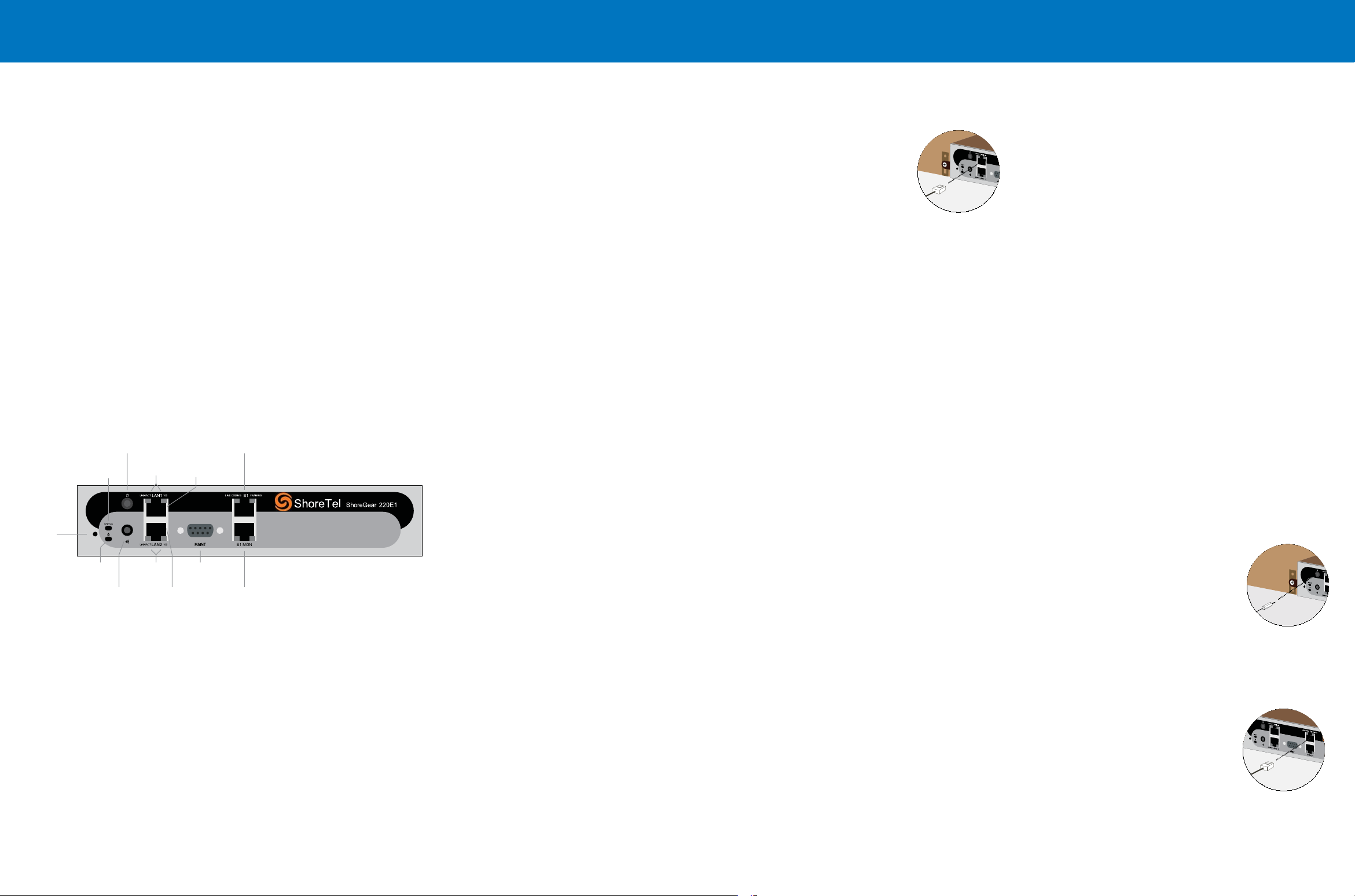
Default
Switch
Audio Output Port
(night bell)
Power
LED Network
LEDs
LAN 2
Connector
RS-232C
Maintentance
Port
Status
LED
Audio Input Port
(music on hold)
Network
LEDs LAN 1
Connector
Monitor
Port
Telco
Port
Installing the ShoreGear 220E1 in a 19-inch Rack
The SG-220E1 is placed in a 19-inch rack only by mounting a ShoreGear Dual Tray into
the rack, then installing the SG-220E1 into the Tray. You can install the SG-220E1 on the
left or right side of the tray.
Refer to the Quick Install Guide for the ShoreGear Dual Tray for Tray installation
instructions and information on using the tray.
Use an RJ-45 E1 cable to connect your E1 line to the Telco port.
For detailed information on switch port and trunk configuration,
see the sections “Configuring Switches” and “Configuring Trunks”
in the ShoreTel Administration Guide.
Connecting an E1 Line
After setting up the network connections and configuring the ShoreGear 220E1 Voice
Switch for operations, you can connect your E1 line to the switch.
Powering on the ShoreGear Voice Switch
After connecting the switch to the network, power on the device by connecting it to an
AC power source.
Plug an AC surge protector (not provided) into a grounded AC power source.
Plug one end of the provided power cord into the receptacle on the back of the
switch, then plug the other end into the AC surge protector.
The power LED flashes momentarily, and remains lit.
If the LED is not lit, make sure the power cord is plugged into the switch and the
power source.
If the LED continues flashing, there is an internal error. Unplug the switch to power
it off, then power it back on. Refer to the “Configuring Switches” chapter in the
ShoreTel Administration Guide for information on flash patterns, or contact the
ShoreTel Support Services at http://www.shoretel.com.
The LAN ports auto-sense the network transport rate. When the network connection is
established, the network LED indicates a transport rate of 10 Mbps or 100 Mbps, and
whether the switch is receiving and transmitting data.
1.
2.
•
•
Use an RJ-45 Ethernet cable to connect one or both of the LAN
ports to the network subnet.
While both ports can detect and respond to link status, the switch
uses only one LAN port at a time.
Connecting the ShoreGear Voice Switch to the Network
Once the ShoreGear 220E1 Voice Switch is secured to a rack or surface-mounted, you
can connect it to the data network.
Optional Connections
After connecting the voice switch to the LAN, you can make optional connections,
including input from a music-on-hold source or output to your internal paging system.
Connect a music-on-hold source (CD player or other audio
source) to the audio input port.
Connect your site’s paging system to the audio output port.
1.
2.
Installation Location Requirements
To ensure optimum operating conditions for the SG 220E1 voice switch, verify the
operating environment is adequately ventilated, free of gas or airborne particles, and
isolated from electrical noise.


