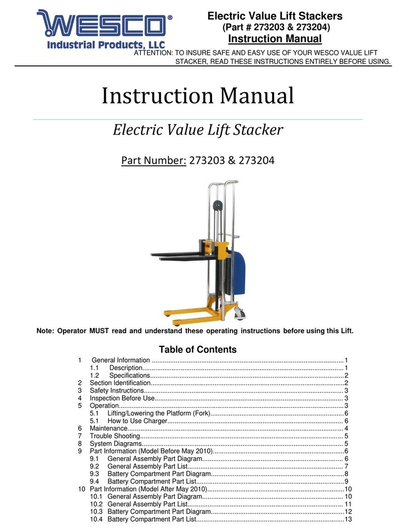
Wesco 272460 User manual

Page1of26
©Copyright 2018 WESCO Industrial Products, LLC. Specifications subject to change. Not responsible for errors or omissions.
TABLE OF CONTENTS
1 General Information ........................................................................................................................... 2
1.1 Description.............................................................................................................................. 2
1.2 Specifications.......................................................................................................................... 2
2 Safety Information................................................................................................................................ 2
3 Assembly.....……….............................................................................................................................. 2
4 Hydraulic Valve Adjustment................................................................................................................. 2
5 Operation..............................................................................................................................................4
6 Battery Charging & Replacement.........................................................................................................5
7 Maintenance.........................................................................................................................................7
8 Trouble Shooting.................................................................................................................................. 8
9 Hydraulic & Circuit Diagrams............................................................................................................... 9
9.1 Hydraulic Flow Diagram (Models Manufactured Before 2010)................................................ 9
9.2 Circuit Diagram (Models Manufactured Before 2010)..............................................................9
9.3 Hydraulic Flow Diagram (Models Manufactured Between 2010 & 2015).................................10
9.4 Circuit Diagram (Models Manufactured Between 2010 & 2015).............................................. 10
9.5 Hydraulic Flow Diagram (Models Manufactured After 2015)................................................... 11
9.5 Circuit Diagram (Models Manufactured After 2015).................................................................11
10 Part Information (Models Manufactured Before 2010)......................................................................... 12
10.1 Handle Part Diagram................................................................................................................12
10.2 Handle Part List........................................................................................................................12
10.3 Frame Part Diagram.................................................................................................................13
10.4 Frame Part List.........................................................................................................................13
10.5 Pump Part Diagram..................................................................................................................14
10.6 Pump Part List..........................................................................................................................14
10.7 Steer Wheel Assembly Part Diagram.......................................................................................15
10.8 Steer Wheel Assembly Part List...............................................................................................16
10 Part Information (Models Manufactured Between 2010 & 2015)......................................................... 17
10.1 Frame & Handle Part Diagram.................................................................................................17
10.2 Frame & Handle Part List.........................................................................................................18
10.3 Pump Part Diagram..................................................................................................................19
10.4 Pump Part List..........................................................................................................................20
11 Part Information (Models Manufactured After 2015)............................................................................ 21
11.1 Handle Part Diagram................................................................................................................21
11.2 Handle Part List........................................................................................................................21
11.3 Frame Part Diagram.................................................................................................................22
11.4 Frame Part List.........................................................................................................................22
11.5 Pump Part Diagram..................................................................................................................23
11.6 Pump Part List..........................................................................................................................24
11.7 External Charger Part Diagram................................................................................................25
11.8 External Charger Part List........................................................................................................26
WESCOINDUSTRIALPRODUCTS,LLC
InstructionManual
ElectricNon‐TelescopingHighLiftTruck
PartNumber: 272460&272461
Note: Operator MUST read and understand these operating instructions before using
this High Lift Truck.
Page2of26
©Copyright 2018 WESCO Industrial Products, LLC. Specifications subject to change. Not responsible for errors or omissions.
Electric Non-Telescoping High Lift Truck
(Part # 272460 & 272461)
Instruction Manual
ATTENTION: TO INSURE SAFE AND EASY USE OF YOUR HIGH LIFT TRUCK,
READ THESE INSTRUCTIONS ENTIRELY BEFORE USING.
WARNING: The battery in this product contains lead. The State of California under
Proposition 65 has determined that exposure to lead is known to cause cancer or birth
defects or other reproductive harm. Please wash hands after use.
1. GENERAL INFORMATION
1.1 DESCRIPTION
Thank you for purchasing an Electric Non-Telescoping High Lift Truck. This truck has been
designed for transporting and horizontal lifting of loads of up to 2,200 lbs. The electric high lift trucks
feature a one year pump warranty and a battery powered hydraulic lift system that is operated with fingertip
controls. It can greatly reduce labor and increase working efficiency and is an efficient tool for various work
environments.
1.2 SPECIFICATIONS
Model 272460 272461
Capacity 2,200 lbs 2,200 lbs
Weight 367 lbs 372 lbs
Fork Lowered Height 3.3” 3.3”
Fork Raised Height 31” 31”
Single Fork Width 6.5” 6.5”
Fork Length 45” 45”
Overall Width 21” 27”
Overall Length 60” 63”
Overall Height 48.5” 48.5”
Telescoping No No
Steering & Load Wheels Polyurethane Polyurethane
Materials and specifications are subject to change without notice.
2. SAFETY INFORMATION
1) Read the manual carefully before operation. Go through every procedure as required in the
manual.
2) Lift the fork to its full range a few times before use to release the air in the hydraulic system.
3) Do not lift or pull personnel with the truck.
4) Do not operate the unit on sloped or tilted surfaces.
5) Do not put your hand or foot under the fork or into the moving parts
6) Put all loads in the center of the fork.
7) The safety valve in the pump station will automatically open when the unit becomes overloaded. If
this occurs, don’t try to lift the load any more by pushing the “UP” button. This will reduce the
lifespan of the pump unit.
8) Power off the unit when not in use.
9) To replace or fill hydraulic oil, the fork should be lowered to its lowest position. The oil to be used
should be clean and filtered. The condensation point of the oil should be ≤-4˚F (-20˚C), and the
motion viscosity should be 20–30 cst.
Note: Hydraulic Oil ISO VG 32 and multipurpose lubricating grease ZG2# or 3# are recommended
for maintenance of this unit.

Page3of26
©Copyright 2018 WESCO Industrial Products, LLC. Specifications subject to change. Not responsible for errors or omissions.
Electric Non-Telescoping High Lift Truck
(Part # 272460 & 272461)
Instruction Manual
ATTENTION: TO INSURE SAFE AND EASY USE OF YOUR HIGH LIFT TRUCK,
READ THESE INSTRUCTIONS ENTIRELY BEFORE USING.
3. INITIAL ASSEMBLY
1) Insert the handle arm (Item 1, Fig. 2) into the pump
piston, then use a hammer to insert the axle with
hole into the hydraulic pump and handle arm from
right to the left (Fig. 3).
2) Set the control lever of the handle to the ‘LOWER’
position, then pass the adjusting nut, adjusting bolt
through the hole of the axle with your hand (Fig. 1).
3) Press the handle arm down; take away the pin
(Item 2, Fig. 2).
4) Set the control lever of the handle to ‘LIFT’
position, then raise the lever plate with the pin
(Item 2, Fig. 2) and insert the adjusting bolt into the
front slot of lever plate. Note: Keep the adjusting
nut under the lever plate.
5) Use a hammer to insert the 2nd dowel pin (Item 5,
Fig. 2) into the 2nd hole of the axle. The draw-bar is
now assembled to the pump.
6) Connect the control cable. Fix the cable at the
pump side in a way that the cable holder can be
turned. Fix the cable before the plug with the pre
assembled cable strip.
4. HYDRAULIC VALVE ADJUSTMENT
On the handle of your pallet truck, you will find the control
lever, which can be regulated in three positions:
Lower : handle up, the lever moves back to the neutral
Neutral : handle in center position
Lift : handle down
If necessary, you can adjust the lever according to
following steps (Fig. 4):
• If the forks elevate while pumping in the Neutral
position, turn the adjusting nut on the adjusting bolt
clockwise until pumping does not raise the forks and the
Neutral position works properly.
• If the forks descend while pumping in the Neutral
position, turn the adjusting nut counter-clockwise until the
forks do not lower.
• If the forks do not descend when the control handle is in
the Lower position, turn the adjusting nut clockwise until
raising the control handle lowers the forks. Then check
the Neutral position according to fig. 4 and be sure that
the adjusting nut is in the proper position.
• If the forks do not elevate while pumping in the Lift
position, turn the adjusting nut counter- clockwise until the
forks elevate while pumping in the Raise position. Then
check the Lower and Raise position.
Figure 1 Side View with Labels
Figure 2 Handle Assembly
(1-Handle Arm/2-Pin/3-Nut/4-Axle with Hole/
5-Dowel Pin/6-Chassis with Pump Unit)
Figure 3 Axle Assembly
Figure 4 Lever Positions
Spring
Spring Cap
Pum
p
Piston
Roller PinRoller Pin
Pressure Roller
Chain
Draw-Bar
Axle With Hole
Adjusting Bolt
Adjusting Nut
Lever Plate
1
4556
23
Lower
Neutral
Lift

Page4of26
©Copyright 2018 WESCO Industrial Products, LLC. Specifications subject to change. Not responsible for errors or omissions.
Electric Non-Telescoping High Lift Truck
(Part # 272460 & 272461)
Instruction Manual
ATTENTION: TO INSURE SAFE AND EASY USE OF YOUR HIGH LIFT TRUCK,
READ THESE INSTRUCTIONS ENTIRELY BEFORE USING.
5. OPERATION
5.1 Parking
Lower the forks to the lowest position and park the truck on a smooth and even level ground. If
equipped with a brake use the brake for parking the truck according to the description further below.
5.2 Lifting
Check that the load does not exceed the loading capacity of the pallet truck. Roll the pallet truck with its
forks slowly under the pallet/load until the back end of the fork rests against the load. Shift the
operating lever down to the Lifting position.
Lift the load by up- and down movements of the handle. The load must be evenly distributed across
both forks.
The truck is equipped with 2 supports. At a height of approx. 15-3/4” (400 mm), the supports
automatically set onto the floor. Once the supports are in place, further movement is not allowed.
For the electric version press the lifting button (Fig. 1, pos. 9) to perform the lifting function.
5.3 Lowering
DO NOT PUT FOOT OR HAND UNDER OR INTO THE LIFTING MECHANISM.
Lower the load by shifting the operating lever up to the lowering position carefully. By releasing the
lever, the lowering movement will stop. Ensure there is adequate clearance behind it and then move
the pallet truck away.
Lowering can also be achieved by the pedal on the side of the truck.
5.4 Moving
• Do not operate the truck on a slope or inclined surface.
• Watch out for different floor levels when moving the unit.
• Make the load stable to prevent it from falling off the unit.
Move the truck by pushing or pulling the handle. The handle is connected to the steering rollers. The
wheels are steered automatically by moving or steering the handle.
5.5 Malfunctions
If there are any malfunctions or the truck is inoperative, please stop using it. Place the truck at a safe
place and avoid further usage. Immediately inform the manager and, or call your distributor.

Page5of26
©Copyright 2018 WESCO Industrial Products, LLC. Specifications subject to change. Not responsible for errors or omissions.
Electric Non-Telescoping High Lift Truck
(Part # 272460 & 272461)
Instruction Manual
ATTENTION: TO INSURE SAFE AND EASY USE OF YOUR HIGH LIFT TRUCK,
READ THESE INSTRUCTIONS ENTIRELY BEFORE USING.
6. BATTERY CHARGING AND REPLACEMENT
• Only qualified personnel are allowed to service or charge the batteries. The instructions of this
manual and from the battery manufacturer must be observed.
• 12V/52Ah
• These batteries are maintenance free; re-filling is prohibited.
• Park the truck securely before starting charging or installing/changing the batteries
• Before finishing maintenance work, make sure, that all cables are connected correctly.
6.1 Replacement
FOR REPLACEMENT YOU NEED TO LIFT THE TRUCK. BLOCK THE SCISSOR MECHANISM
TO PREVENT LOWERING!
Park the truck securely, switch off the truck with the key switch and remove the emergency plug.
Loosen the upper cover with the 2 screws. Also remove the backside fixing bar (also with 2 screws).
Disconnect the terminals (Fig. 4) and take the
battery out.
The installation is in the reverse order of the
removal. Please connect the positive terminals
firstly; otherwise the truck could be damaged.
6.2 Battery indicator
Discharge status is indicated by ten red LED segments.
Battery Discharged Battery Fully Charged
Fig.5: Battery Discharge Indicator
• When the battery is properly charged, all the LED illuminate. During discharge successively less
LEDs lights up.
• When the last 3 LEDs are lit, the battery is fully discharged. The battery must be charged before
further operation, otherwise the lifetime of the battery will be reduced and/or the battery could be
damaged!
Fig.4: Battery Replacement

Page6of26
©Copyright 2018 WESCO Industrial Products, LLC. Specifications subject to change. Not responsible for errors or omissions.
Electric Non-Telescoping High Lift Truck
(Part # 272460 & 272461)
Instruction Manual
ATTENTION: TO INSURE SAFE AND EASY USE OF YOUR HIGH LIFT TRUCK,
READ THESE INSTRUCTIONS ENTIRELY BEFORE USING.
6. BATTERY CHARGING AND REPLACEMENT (CONTINUED)
6.3 Charging
Using Onboard Charger
• The attached automatic charger is only available for the optional voltage of 110V or 220V as referred.
• The exactly charge status can be only checked from the discharge indicator. To control the status, the
charging must be interrupted and the truck must be started.
• Park the truck at a dedicated secured area with a dedicated power supply. Lower the forks and
remove the load. Switch the truck off and connect the main power connector to the power supply. The
charger starts charging the battery.
• This Charger features a three-stage charging function with automatic switching from 1st stage to the
next stage.
Stage 1: Constant current charging
Stage 2: Constant voltage charging
Stage 3: Floating charging
Following the increase of the electricity in the battery, the charging electrical current is reducing, the
charger steps into the 3rd stage automatically.
1.) SPECIFICATIONS
Input Volt: 150 – 260 V, AC 50 – 60 Hz
Output Volt: 145 V ±0.3
Output Current: 5 – 6 Amp
Applicable Ambient Temperature: –15 - +65
2.) OPERATION
a. Insert the plug of the power cable into the socket of the power line. The Power Indicator lights (red)
and then Charging Indicator turns on red, indicating the battery is in charging.
b. When Charging Indicator turns from red to green, the battery is nearly full. Charging can continue in
the Floating Stage.
c. When the battery is fully charged, disconnect the Power Cable from the Power Line.
3.) WARNING
a. During charging the truck can’t be lifted electrically!
b. Do not use the truck in wet areas or conditions.
Table 3: Charging LED
LED- Signal Function
Red Battery discharged
Green Fully charged
When charging is finished, disconnect the connector from the socket and place it in the designated
pocket.
External Charger
The external charger automatically selects the charging state according to the detected battery voltage
and converts into floating charge state when the battery is fully charged.
Disconnect the Emergency plug and connect the charger plug with the battery sided connector.
Connect the power cord of the charger to the main power supply. After switching on the charger, the
charging starts automatically.

Page7of26
©Copyright 2018 WESCO Industrial Products, LLC. Specifications subject to change. Not responsible for errors or omissions.
Electric Non-Telescoping High Lift Truck
(Part # 272460 & 272461)
Instruction Manual
ATTENTION: TO INSURE SAFE AND EASY USE OF YOUR HIGH LIFT TRUCK,
READ THESE INSTRUCTIONS ENTIRELY BEFORE USING.
7. MAINTENANCE
Only qualified and trained personnel are allowed to do service on this truck.
• Before servicing the truck, remove the load and lower the forks to the lowest position.
• Completely immobilize the truck before working on components that might pinch fingers or hands if
movement were allowed.
• Use approved original spare parts from your dealer.
• Please consider that leakage of hydraulic fluid can cause failures and accidents.
• It is recommended to allow only trained service technicians to adjust the pressure valve.
• All bushings and bearings have been lubricated at the factory. To increase their life, regular
maintenance is recommended. Using the appropriate grease for the application and lubricate each
grease fitting every 6 months.
• Harsh environments may require more frequent maintenance.
7.1 Maintenance Checklist
DAILY
Check the truck on the following points before operation.
Remove load from truck and lower the forks to the lowest position.
DO NOT USE THE TRUCK IF ANY MALFUNCTION OR FAULT IS FOUND.
• Check for visible structural deformation or cracks of arms, forks, or any other component; and
unusual noise or binding of the lifting mechanism.
• Check if there is any oil leakage.
• Check the vertical creep of the lifting mechanism.
• Check for smooth movement of the wheels.
• Check if there are any particles or damages on the wheels.
• Check if all the bolts and nuts are tightened firmly.
MONTHLY
• All bearings and shafts are provided with long- life grease at the factory. Long-life grease should be
applied to the lubrication points at monthly intervals or after each time the truck is cleaned.
• Clean off dirt and debris.
EVERY THREE MONTHS
• Check the set-up of the drain-valve
ANNUALLY
• Change the oil (more frequently if color has substantially darkened or feels gritty). The required
hydraulic fluid type is ISO VG32, its viscosity should be 30cSt at 40°C, total volume is about 33.8-44 fl
oz (1-1.3 L).
• Check all parts of the truck for wear and replace defective parts where necessary.
NOTE: If hydraulic oil is milky white in color, water is in the hydraulic system. Change the hydraulic oil
immediately.
7.2 Deaerating the Hydraulic System
Air may find its way into the pump during transportation, tilting or usage on uneven ground. It can result
in the forks no longer rising while pumping in the ‘Lift’ position. The air can be removed in the following
way:
Move the control handle to the Lower position, move then the tiller down several times. Thereafter
normal operation can be resumed.
7.3 Check and Refill Hydraulic Oil
1) Ensure forks are in lowered position.
2) Lay pallet truck on side. Position drain plug of hydraulic cylinder up.
3) Remove the screw plug.
4) Add hydraulic oil until level of oil is at bottom of hole.
5) Replace drain plug, upright the truck

Page8of26
©Copyright 2018 WESCO Industrial Products, LLC. Specifications subject to change. Not responsible for errors or omissions.
Electric Non-Telescoping High Lift Truck
(Part # 272460 & 272461)
Instruction Manual
ATTENTION: TO INSURE SAFE AND EASY USE OF YOUR HIGH LIFT TRUCK,
READ THESE INSTRUCTIONS ENTIRELY BEFORE USING.
8. TROUBLESHOOTING
Failure Cause Solution
1 Motor and hydraulic
pump do not
operate
Defective fuse FU1 and/or FU2 Replace the fuse
Loose or unconnected plug Reconnect
Motor is burned out Replace motor
2
The high-lift pallet
truck does not lift
the load, although
the pump is working
perfectly
Load is too heavy, overload valve is actuated,
Control lever is out of adjustment Reduce the load
Lowering valve does not close any more or the
valve face is not sealed because of dirt, piston
rod is starting to rust
Clean or replace it
Electric circuit is disconnected Check the wiring
Electromagnetic switch KM is defective Replace the contactor KM
Lifting switch is obstructed, resp. defective Check resp. replace the
lifting switch
Hydraulic pump does not work Check the pump
3 Raised load is
lowered on its own.
Leakage in the hydraulic system Seal
Lowering valve does not close any more or the
valve unit is not sealed because of dirt Clean or replace
Incorrect valve set-up. Adjust lowering valve
Pressure relief valve (pump) is leaky (pump
turns slowly backwards.) Clean or replace the valve
4 Oil loss on hydraulic
cylinder Sealing elements are worn Replace sealing elements
5 The raised load is
lowered too slowly
Temperature too low – the hydraulic system oil
is too thick Find a warmer location
6 Fork does not raise
to upper position
Insufficient oil in the tank Refill with oil (while the fork
is lowered)
Battery discharged Charge the battery
7 Battery capacity too
low
Battery is not charged enough Recharge
Battery is defective Replace the battery
8 Battery cannot be
charged
Fuse FU2 is defective Replace FU2
Battery resp. charger defective Replace battery resp.
charger
9 Battery discharges
too quickly
Silted battery Replace battery
Sulphating or other failure in the battery. Replace battery
Accidental ground contact in the electric
system or battery. Repair or replace battery

Page9of26
©Copyright 2018 WESCO Industrial Products, LLC. Specifications subject to change. Not responsible for errors or omissions.
Electric Non-Telescoping High Lift Truck
(Part # 272460 & 272461)
Instruction Manual
ATTENTION: TO INSURE SAFE AND EASY USE OF YOUR HIGH LIFT TRUCK,
READ THESE INSTRUCTIONS ENTIRELY BEFORE USING.
9. HYDRAULIC & CURCUIT DIAGRAMS
9.1 Hydraulic Flow Diagram (Models Manufactured Before 2010)
9.2 Circuit Diagram (Models Manufactured Before 2010)

Page10of26
©Copyright 2018 WESCO Industrial Products, LLC. Specifications subject to change. Not responsible for errors or omissions.
Electric Non-Telescoping High Lift Truck
(Part # 272460 & 272461)
Instruction Manual
ATTENTION: TO INSURE SAFE AND EASY USE OF YOUR HIGH LIFT TRUCK,
READ THESE INSTRUCTIONS ENTIRELY BEFORE USING.
9. HYDRAULIC & CURCUIT DIAGRAMS
9.5 Hydraulic Flow Diagram (Models Manufactured Between 2010 & 2015)
9.6 Circuit Diagram (Models Manufactured Between 2010 & 2015)

Page11of26
©Copyright 2018 WESCO Industrial Products, LLC. Specifications subject to change. Not responsible for errors or omissions.
Electric Non-Telescoping High Lift Truck
(Part # 272460 & 272461)
Instruction Manual
ATTENTION: TO INSURE SAFE AND EASY USE OF YOUR HIGH LIFT TRUCK,
READ THESE INSTRUCTIONS ENTIRELY BEFORE USING.
9. HYDRAULIC & CURCUIT DIAGRAMS (CONTINUED)
9.3 Hydraulic Flow Diagram (Models Manufactured After 2015)
9.4 Circuit Diagram (Models Manufactured After 2015)

Page12of26
©Copyright 2018 WESCO Industrial Products, LLC. Specifications subject to change. Not responsible for errors or omissions.
Electric Non-Telescoping High Lift Truck
(Part # 272460 & 272461)
Instruction Manual
ATTENTION: TO INSURE SAFE AND EASY USE OF YOUR HIGH LIFT TRUCK,
READ THESE INSTRUCTIONS ENTIRELY BEFORE USING.
10. PART INFORMATION (MODELS MANUFACTURED BEFORE 2010)
10.1 HANDLE PART DIAGRAM
10.2 HANDLE PART LIST
Wesco
Replacement
Part # No. Description Qty Wesco
Replacement
Part # No. Description Qty
101 Release Rod 1 116 Spring 1
102 Chain 1 117 Pin 1
103 Adjusting Bolt 1 118 Handle 1
104 Adjusting Nut 1 119 Pin 1
105 Axle with Hole 1 120 Controlling Handle 1
106 Elastic Pin 2 121 Pull Board 1
107 Bushing 2 122 Pin 1
108 Roller Pin 1 123 Rubber Band 1
109 Pressure Roller 1 124 Screw 2
110 Bushing 1 125 Socket of Switch 1
111 Draw - bar 1 272474 126 Switch 1
112 Pin 4 127 Socket of Button 1
113 Screw 4 128 Button 1
114 Cover 1 129 Connector Plug 1
115 Ball 1 273057 101-129 Handle Assembly 1

Page13of26
©Copyright 2018 WESCO Industrial Products, LLC. Specifications subject to change. Not responsible for errors or omissions.
Electric Non-Telescoping High Lift Truck
(Part # 272460 & 272461)
Instruction Manual
ATTENTION: TO INSURE SAFE AND EASY USE OF YOUR HIGH LIFT TRUCK,
READ THESE INSTRUCTIONS ENTIRELY BEFORE USING.
10. PART INFORMATION (MODELS MANUFACTURED BEFORE 2010)
10.3 FRAME PART DIAGRAM
10.4 FRAME PART LIST
Wesco
Replacement
Part # No. Description Qty Wesco
Replacement
Part # No. Description Qty
201 Fork Frame 1 214 Elastomeric Gasket
202 Bolt 1 215 Nut 2
203 Screw 2 216 Inner Leg 1
204 Gasket 2 217
205 Screw 2 218 Elastic collar 4
206 Pin 2 219 Shaft of Roller 2
207 Bushing 2 220
208 Elastic collar 10 221
209 Left Leg 2 222 Roller 2
210 Bushing 2 223 Steel Roller 4
211 Pin 2 224 Gasket 4
212 Centrifugal Axle 2 225 Bearing 4
213 Bushing 2

Page14of26
©Copyright 2018 WESCO Industrial Products, LLC. Specifications subject to change. Not responsible for errors or omissions.
Electric Non-Telescoping High Lift Truck
(Part # 272460 & 272461)
Instruction Manual
ATTENTION: TO INSURE SAFE AND EASY USE OF YOUR HIGH LIFT TRUCK,
READ THESE INSTRUCTIONS ENTIRELY BEFORE USING.
10. PART INFORMATION (MODELS MANUFACTURED BEFORE 2010)
10.5 PUMP PART DIAGRAM
10.6 PUMP PART LIST
Wesco
Replacement
Part # No. Description Qty Wesco
Replacement
Part # No. Description Qty
301 Locking Ring 1 320 Valve Cartridge 1
302 Gasket for Spring 1 321 Nut 1
303 Piston 1 322 Screw 1
304 Spring 1 323 Lever Plate 1
305 Dust Ring 1 324 Pump Body 1
306 Y - Ring 1 325 Cylinder 1
307 Pump Cylinder 1 326 Seal Gasket 1
308 O - Ring 1 327 Bushing 1
309 Seal Gasket 1 328 Screw Cover 1
310 Screw Plug 1 329 O - Ring 1
311 Screw Plug 1 330 Dust Ring 1
312 O - Ring 1 331 Steel Ball 1
313 Adjusting Bolt 1 332 Piston Rod 1
314 Spring 1 333 Piston 1
315 Spindle of Safety Valve 1 334 Cup Packing 1
316 Elastic Pin 1 335 O - Ring 1
317 Lower Cylinder 1 336 Gasket 1
318 O - Ring 1 337 Elastic collar 1
319 O - Ring 1 272471
Complete Replacement
Pump 1

Page15of26
©Copyright 2018 WESCO Industrial Products, LLC. Specifications subject to change. Not responsible for errors or omissions.
Electric Non-Telescoping High Lift Truck
(Part # 272460 & 272461)
Instruction Manual
ATTENTION: TO INSURE SAFE AND EASY USE OF YOUR HIGH LIFT TRUCK,
READ THESE INSTRUCTIONS ENTIRELY BEFORE USING.
10. PART INFORMATION (MODELS MANUFACTURED BEFORE 2010)
10.7 STEER WHEEL ASSEMBLY DIAGRAM

Page16of26
©Copyright 2018 WESCO Industrial Products, LLC. Specifications subject to change. Not responsible for errors or omissions.
Electric Non-Telescoping High Lift Truck
(Part # 272460 & 272461)
Instruction Manual
ATTENTION: TO INSURE SAFE AND EASY USE OF YOUR HIGH LIFT TRUCK,
READ THESE INSTRUCTIONS ENTIRELY BEFORE USING.
10. PART INFORMATION (MODELS MANUFACTURED BEFORE 2010)
10.8 STEER WHEEL ASSEMBLY PART LIST
Wesco
Replacement
Part # No. Description Qty Wesco
Replacement
Part # No. Description Qty
401 Seal Gasket 6 435 Screw 2
402 Connector 1 436 Gasket 2
403 Bolt 3 437 Motor Cover 1
404 Nut 2 438
405 Oil Pipe 1 439
406 Carve Tie-in 1 440 Battery Cover 1
407 Seal Gasket 1 441 Nut 4
408 Spring 1 442 Screw 2
409 Steel Ball 1 443 Fuse 1
410 Seat of Valve 1 444 Fuse Carrier 1
411 Seal Gasket 1 445 Bolt 2
412 Connector 1 446 Rubber band 2
272500 413 Bushing 1 447 Connector plug 1
414 Seat of Bearing 1 448
415 Bearing 1 449 Screw 2
272497 416 Dust Cover 2 450 Fuse Carrier 2
272498 417 Elastic collar 4 451 Fuse 1
272499 418 Bearing 4 452 Screw 2
419 Wheel 4 453 Seat of Voltage Meter 1
420 Holding Site for Wheel 1 454 Voltage Meter 1
421 Bolt 1 455
422 Bushing 2 456 Circuit Module 1
423 Thrust Plate 1 457
424 Bushing 1 458
425 Cover 1 459
426 Screw 2 460 Screw 2
427 Oil Pipe 1 461 Rubber band 2
428 Nut 2 462 Socket 1
429 Connector 1 463 Screw 2
430 Motor Assembly 1 109102 464 Battery 1
431 Bolt 2 465 Screw 2
432 Electromagnetic Switch 1 466 Baffle 1
433 Gasket 2 467 Battery Wires 2
434 Nut 2 272472 Charger 1

Page17of26
©Copyright 2018 WESCO Industrial Products, LLC. Specifications subject to change. Not responsible for errors or omissions.
Electric Non-Telescoping High Lift Truck
(Part # 272460 & 272461)
Instruction Manual
ATTENTION: TO INSURE SAFE AND EASY USE OF YOUR HIGH LIFT TRUCK,
READ THESE INSTRUCTIONS ENTIRELY BEFORE USING.
11. PART INFORMATION (MODELS MANUFACTURED BETWEEN 2010 & 2015)
11.1 FRAME & HANDLE PART LIST
11.2 FRAME & HANDLE PART LIST
Wesco
Replacement
Part # No. Description Qty Wesco
Replacement
Part # No. Description Qty
273728 01 Front Wheel 2 70 Hold Yoke 1
272489 02 Ball Bearing 8 71 Bush 1
03 Washer 6 72 Snap Ring 1
04 Snap Ring 16 73 Ball Bearing 1
05 Pin 2 74 Ball 42
06 Leg 2 75 Wheel Yoke 1
273658 07 Screw 2 76 Screw 1
08 Bush 2 201 Screw 2
10 Ball Bearing 4 203 Fuse Box 1
11 Leg 1 204 Nut 4
12 Centrifugal Axle 2 205 Screw 9
13 Bush 2 206 Fuse (160A) 1
14 Washer 4 207 Fuse (5A) 1
15 Bush 2 208 Fuse Box 2
16 Nut 2 209 Screw 4

Page18of26
©Copyright 2018 WESCO Industrial Products, LLC. Specifications subject to change. Not responsible for errors or omissions.
Electric Non-Telescoping High Lift Truck
(Part # 272460 & 272461)
Instruction Manual
ATTENTION: TO INSURE SAFE AND EASY USE OF YOUR HIGH LIFT TRUCK,
READ THESE INSTRUCTIONS ENTIRELY BEFORE USING.
11. PART INFORMATION (MODELS MANUFACTURED BETWEEN 2010 & 2015)
11.2 FRAME & HANDLE PART LIST (CONTINUED)
Wesco
Replacement
Part # No. Description Qty Wesco
Replacement
Part # No. Description Qty
272488 17 Steering Wheel 2
211 Cover 1
19 Screw 2
212 Plate 1
20 Nut 1
213 Screw 4
21 Screw 1
109187 214 Battery 1
24 Pin 2
215N Cover 1
25 Bush 2
217 Screw 1
27 Ball Bearing 1
272599 218N Recharger 1
28 Spacer 1
219 Spacer 2
29 Nut 2
220 Nut 2
30 Pin 2
221 Oil Pipe 1
31 Snap Ring 2
222 Screw 2
32 Pin 2
223 Washer 4
33 Screw 2
224 Adjusting Screw 1
34 Bush 2
225 Screw 2
35 Handle Tube 1
226 Cover 1
36 Nut 3
227 Screw 2
37 Eye Bolt 1
272479 228 Pump 1
40 Chain 1
229 Adjusting Screw 1
41 Chain Connector 2
273655 230 Spacer 2
42 Release Rod 1
273656 231 Nut 2
43 Screw 6
273657 232 Oil Pipe 1
44 Cover 1
273731 234 Relay 1
45 Pin 6
235 Washer 1
46 Pin 1
236-1 Switch 1
47 Ball 1
236-2 Switch Base 1
48 Spring 1
237 Screw 2
49 Release Lever 1
238-1 Up Switch 1
51 Handle 1
238-2 Up Switch Base 1
52 Retaining Ring 1
239 Socket 1
53 Washer 1
240 Voltage Meter 1
54 Ball Bearing 1
241 Battery Terminal (-) 1
55 Snap Ring 1
242 Batter Terminal (+) 1
56 Spacer 1
244 Adjusting Screw 1
57 Spacer 1
245 Washer 1
58 Fork 1
246 Ball 1
60 Hooking Plate 1
247 Spring 1
61 Spacer 2
248 Adjusting Screw 1
62 Spacer 2
249 Washer 1
251 Plate 1
Replacement Assemblies
273661 301
Handle Assembly (Includes Items #34, 35, 36, 37, 40, 41, 42, 43, 44, 45, 46, 47, 48, 49,
51, 236-1, 236-2, 205, 235, 237, 238-1 & 238-2) 1
302 Wheel Yoke Assembly (Includes Items # 02, 04, 17, 20, 75 & 76) 1
303 Wheel Assembly (Includes Items #02 & 17) 2
304 Front Wheel Assembly (Includes Items #01 & 02) 2
305 Leg Assembly (Includes Items #01, 02, 03, 04, 05, 06, 07, 08, 61 & 62) 2

Page19of26
©Copyright 2018 WESCO Industrial Products, LLC. Specifications subject to change. Not responsible for errors or omissions.
Electric Non-Telescoping High Lift Truck
(Part # 272460 & 272461)
Instruction Manual
ATTENTION: TO INSURE SAFE AND EASY USE OF YOUR HIGH LIFT TRUCK,
READ THESE INSTRUCTIONS ENTIRELY BEFORE USING.
11. PART INFORMATION (MODELS MANUFACTURED BETWEEN 2010 & 2015)
11.3 PUMP PART DIAGRAM

Page20of26
©Copyright 2018 WESCO Industrial Products, LLC. Specifications subject to change. Not responsible for errors or omissions.
Electric Non-Telescoping High Lift Truck
(Part # 272460 & 272461)
Instruction Manual
ATTENTION: TO INSURE SAFE AND EASY USE OF YOUR HIGH LIFT TRUCK,
READ THESE INSTRUCTIONS ENTIRELY BEFORE USING.
11. PART INFORMATION (MODELS MANUFACTURED BETWEEN 2010 & 2015)
11.4 PUMP PART LIST
Wesco
Replacement
Part # No. Description Qty Wesco
Replacement
Part # No. Description Qty
101 Retaining Ring 1 137 Screw 1
102 Spring Seat 1 138 Plate 1
103 Spring 1 139 Spring 1
104 Wiper 1 140 Release Indicator 1
105 Y-Ring 1 141 O-Ring 1
106 Pump 1 142 Spring 1
107 O-Ring 1 143 Valve Insert 1
108 Plunger 1 144 O-Ring 4
109 Ball 2 145 Ball 1
118 Cylinder Bush 1 146 Release Valve 1
119 O-Ring 1 147 Spring 1
120 O-Ring 1 148 Seal Ring 1
121 Snap Ring 1 149 Screw 1
122 Split Ring 1 150 Snap Ring 1
123 Rubber Sleeve 1 151A Y-Ring 1
124 Pendulum Sleeve 1 152A O-Ring 1
125 Screw 2 153A O-Ring 1
126 O-Ring 3 154A Piston 1
127 Screw 2 155A Piston Rod 1
128 Spring 2 156 Seal Ring 1
129 Ball Seat 2 157 Cylinder Nut 1
130 Pump Housing 1 158 O-Ring 1
133 Cylinder 1 159 Scraper Ring 1
134 Screw 1 160 Screw 1
135 Seal Ring 1 161A Retaining Y-Ring 1
136 Screw 1
Replacement Assemblies
273706 1900 Complete Replacement Pump 1
1901 Pump Assembly (Includes Items #104, 105, 106, 107 & 108) 1
1902
Valve Insert Assembly (Includes Items #140, 141, 142, 143, 144, 145, 146, 147,
148 & 149) 1
1903
Piston Rod Assembly (includes Items #150, 151A, 152A, 153A, 154A, 155A &
161A) 1
1904 Cylinder Nut Assembly (Includes Items #156, 157, 158 & 159) 1
This manual suits for next models
1
Table of contents
Other Wesco Lifting System manuals

Wesco
Wesco 272467 User manual

Wesco
Wesco EVM 206-90 Operation instructions

Wesco
Wesco 273203 User manual

Wesco
Wesco 272468 User manual

Wesco
Wesco DJ-55 Service manual

Wesco
Wesco Gator Grip Drum EGG-1 Operating instructions

Wesco
Wesco HWLFX-4 User manual

Wesco
Wesco POWER-LIFT STACKER Service manual

Wesco
Wesco DM-800-MDT Service manual
Popular Lifting System manuals by other brands

Meganex
Meganex MEG73 instruction manual

Zepro
Zepro ZHZ 500 Installation instruction

Tommy Gate
Tommy Gate Original TG-67 Mounting instructions

Harmar Mobility
Harmar Mobility Highlander CPL400 Installation and owner's manual

Ravaglioli
Ravaglioli RAV4352 manual

MARTINS Industries
MARTINS Industries MTWL user manual