Simpro EUROVER User manual

User Manual // Simpro Eurover
Original Instructions // English // v34.0 // April 2022
USER MANUAL

Copyright © 2022 Simpro Handling Equipment Ltd.
No part of this document may be reproduced or transmitted in any form or by any means,
electronic, mechanical, photocopying, recording, or otherwise, without the written
permission of Simpro Handling Equipment Ltd.
For the purposes of standards compliance and international conformity, this document uses
Système International (SI) units. These may be converted to Imperial units as follows:
1 kilogram (kg) = 2.2 pounds (lb)
1 metre (m) = 1000 millimetres (mm) = 39.37 inches (in) = 3.28 feet (ft) = 1.09 yards (yd)
The following stylistic conventions are used throughout this document:
Point of interest
Point of warning
§Internal cross-reference (hyperlink in PDF edition)
Simpro partcode (hyperlink in PDF edition)
Errors in this document should be reported to info@simpro.world

User Manual // Simpro Eurover
Original Instructions // English // v34.0 // April 2022 // Page 2
1030
2790
1045
EO2200 Standard Layout

Contents
1. Product Overview........................................................................................................ 5
1.1 Key Features .......................................................................................................................... 5
1.2 Construction .......................................................................................................................... 5
1.3 Mechanism ............................................................................................................................ 6
1.4 Safe Lifting Capacity ............................................................................................................ 6
1.5 Duty cycle.............................................................................................................................. 6
1.6 Service life.............................................................................................................................. 6
1.7 Noise emissions ...................................................................................................................... 6
1.8 Environmental restrictions .................................................................................................... 7
1.9 Ingress protection ................................................................................................................. 7
1.10 Notes ...................................................................................................................................... 7
2. Operating Instructions ................................................................................................. 8
2.1 Before use .............................................................................................................................. 8
2.2 Emptying bins ........................................................................................................................ 8
2.3 Operating norms ...................................................................................................................9
3. Care and Maintenance............................................................................................ 11
3.1 Quick Troubleshooting Guide............................................................................................ 11
3.2 Adjusting the tipping height .............................................................................................. 11
3.3 Cleaning ..............................................................................................................................12
3.4 Cradle jams ......................................................................................................................... 12
3.4.1 Cradle jams while raising.............................................................................................................. 12
3.4.2 Cradle jams while lowering.......................................................................................................... 13
3.5 Electrical System .................................................................................................................14
3.5.1 International conformance ......................................................................................................... 14
3.5.2 Appliance inlet.............................................................................................................................. 14
3.5.3 Emergency stop ............................................................................................................................ 14
3.5.4 Motor.............................................................................................................................................. 14
3.6 Preventative Maintenance Inspections ........................................................................... 15
3.6.1 Pre-inspection checklist................................................................................................................ 15
3.6.2 Monthly inspection........................................................................................................................ 15
4. Installation, Handling & Storage ............................................................................... 17
4.1 Installing................................................................................................................................ 17
4.1.1 Before installing ............................................................................................................................. 17
4.1.2 Erecting the mast .......................................................................................................................... 17

User Manual // Simpro Eurover
Original Instructions // English // v34.0 // April 2022 // Page 4
4.1.3 Connecting the power................................................................................................................. 18
4.1.4 Commissioning .............................................................................................................................. 18
4.2 Moving ................................................................................................................................. 19
4.3 Lifting .................................................................................................................................... 19
4.4 Transporting ......................................................................................................................... 20
4.5 Storing................................................................................................................................... 20
5. Safety Assessment...................................................................................................... 21
5.1 Safety features .................................................................................................................... 21
5.2 Reasonably foreseeable misuse ....................................................................................... 21
5.3 ISO12100 Hazard and Risk Assessment Guide ................................................................. 21
5.3.1 The ISO12100 risk assessment model ........................................................................................... 22
5.3.2 Identified Hazards ......................................................................................................................... 23
5.3.3 Residual Hazards ........................................................................................................................... 25
5.4 ISO13849 (AS/NZS4024) Conformance Guide................................................................. 26
5.4.1 The ISO13849 functional safety model........................................................................................ 26
5.4.2 Identifying the required safety functions.................................................................................... 26
5.4.3 Determining the required Performance Level of safety functions........................................... 26
5.4.4 Achieving the required Performance Level............................................................................... 27
6. Spare Parts.................................................................................................................. 28
7. Accessories................................................................................................................. 29
8. Technical Data........................................................................................................... 30
9. Warranty ..................................................................................................................... 31
9.1 Definitions............................................................................................................................. 31
9.2 Coverage ............................................................................................................................ 31
9.3 Exclusions ............................................................................................................................. 31
9.4 End User claim procedure ................................................................................................. 32
9.5 Agent claim handling procedure..................................................................................... 32
10. Notes........................................................................................................................... 33

1. Product Overview
Congratulations on your purchase of a Eurover column lifter from Simpro. These machines are
ideal for food production areas, with a simple, safe design and minimal maintenance
requirements
Eurover tippers are manufactured from SUS304 stainless steel, with food-grade welding and
componentry. They are designed for easy cleaning, with a highly accessible single-mast
design and stainless-steel covers to all components.
Eurover employs a direct chain-drive mechanism which can safely lift bins weighing up to
350kg, backed up by a failsafe brake system. This allows for an adjustable tip height, with
various models tipping in ranges from 1.2m up to 2.5m.
The Eurover quick-hitch retaining system allows bins to be secured simply by rolling them into
place, with no clamping required. At the end of the tipping cycle, pressing down on a foot
catch allows the bins to be instantly released. The system is compatible with a range of
international standard Eurobins and trolleys, also available from Simpro.
Like all Simpro products, Eurover is designed to be exceptionally reliable and suitable for
intensive production applications.
1.1 Key Features
Key features of the Eurover include:
1. A tipping action whereby bins are lifted straight up, and then gently rolled forward
around the lip of the container being emptied into. Benefits of this design include a
small floor footprint, high stability, and an adjustable tipping height.
2. 304-grade stainless steel construction, suitable for hygiene-critical applications.
3. A direct chain-drive lifting mechanism, with a capacity of 350kg.
4. A failsafe braking system to protect against chain failure.
5. A DIN9797 trunnion-lift bin retaining system, suitable for use with industry standard
Eurobins (also available from Simpro).
6. Upper and lower limit switches to prevent overload damage.
7. An extremely reliable, low-maintenance design.
1.2 Construction
The Eurover consists of a 304-grade stainless steel mast, covers, bolt-down base and bin
cradle with spring-loaded latch mechanism, a heavy-duty lifting chain, a sealed enclosure
containing an AC electric motor, gearbox and electronic systems, operator controls, and a
3-phase power lead.

User Manual // Simpro Eurover
Original Instructions // English // v34.0 // April 2022 // Page 6
1.3 Mechanism
When the RAISE circuit is activated, an AC electric motor shaft rotates a sprocket wheel via a
gearbox. The sprocket teeth pull on the lifting chain, causing the sliding block to move
vertically in the mast. The bin cradle moves with the sliding block, and is inverted at the
appropriate height by a fixed roller running in a tipping track.
When the LOWER circuit is activated, the motor is reversed, causing the bin to be lowered
back to ground level. Electronic control systems allow the operator to raise or lower the bin in
a controlled manner.
1.4 Safe Lifting Capacity
The Safe Lifting Capacity of the standard Eurover is 350kg (770lb).
Some machines may be specified with different lifting capacities. Refer to the rating plate to
verify the Safe Lifting Capacity of any given machine.
Safe Lifting Capacity is a gross figure, referring to the weight of the bin, its contents, and
any other external objects which have been placed on the cradle.
Never attempt to lift bins heavier than the machine’s rated Safe Lifting Capacity.
1.5 Duty cycle
The duty cycle of the Eurover depends on various environmental factors and the manner in
which the machine is used. The figures given below are estimates only.
1.6 Service life
The nominal service life of the Eurover is as follows:
Average Gross Bin Weight
Intended operational life
< 200kg
100,000 cycles
200kg –300kg
75,000 cycles
300kg –350kg
50,000 cycles
1.7 Noise emissions
The noise emissions of the Eurover do not usually exceed ~60 dB(A) at the operator’s ear.
Hearing protection is recommended if operating the machine for extended periods.
Duty Cycle (tipping ~250kg per bin at 2200mm)
Net throughput
Number of bins
Units
7,500kg
30 bins
Per hour

ISO standards specify that machinery noise emissions be measured in A-weighted
decibels, or dB(A). This is a unit of volume adjusted to reflect the sensitivity of human
hearing. Measurements for a dB(A) assessment are taken at a point 1.6 metres above the
ground at the operator’s working position.
1.8 Environmental restrictions
The Eurover may be used indoors or outdoors. However the following restrictions apply:
1. Minimum floor area 4 square metres, with a clear passage to exits;
2. Height above sea level not more than 1000m;
3. Ambient temperature not higher than +40℃and not lower than -10℃;
4. At ambient temperatures above 35℃, the relative humidity should not exceed 50%; at
lower temperatures, higher relative humidity is permitted;
Never operate the Eurover in explosive, corrosive, acidic or alkaline environments.
1.9 Ingress protection
Item
IP Rating
Push buttons, switches, and lamps
IP66
Microswitches
IP66
Appliance inlet
IP44
Motor
IP54 (additional protection is provided by covers)
Overall
IP56 (optionally upgraded to IP66 or IP69)
1.10 Notes
1. This User Manual describes approved procedures for the operation, inspection, and
maintenance of the Simpro Eurover bin-tipping machine.
2. This manual is written in English, and is to be considered the ‘Original Instructions’ for
the purposes of EU Machinery Directive 2006/42/EC.
3. Operator(s) must read and understand this manual before using the machine.
4. If the machine is to be leased, sold, or otherwise transferred, then this manual shall
accompany the machine.
5. This is a generic manual. Simpro reserves the right to change the design of our
products at any time. In cases where a discrepancy exists between the manual and
the actual product, the manual is to be used as a reference only.
6. Contact your authorized Simpro agent if any problems or faults are encountered with
the machine.
7. Errors in this manual should be reported by email to info@simpro.world.

User Manual // Simpro Eurover
Original Instructions // English // v34.0 // April 2022 // Page 8
2.Operating Instructions
2.1 Before use
Before operating a Eurover, the following points should be checked to ensure the machine is
stable and safe to use:
1. If being used with a mobile base unit, check that:
a. The machine is correctly positioned beside the destination receptacle.
b. The operating surface is hard and flat with a slope no greater than 1:12.
c. The brakes on both castor wheels are applied.
2. Check that all covers and guarding panels are in place.
3. Check that the power lead is undamaged and firmly connected.
4. Check that all personnel other than the operator are clear of the machine.
5. Check that the EMERGENCY STOP button is released.
6. Check that the cradle is lowered to the ground.
2.2 Emptying bins
1. Wheel a full Eurobin into the cradle, taking care that it is properly positioned, and the
quick-release catch is engaged.
2. Press the RAISE button, holding it down until the Eurobin reaches the inverted position.
3. Wait for 10-20 seconds while the contents of the Eurobin are emptied.
4. Press the DOWN button, holding down until the Eurobin rests on the ground.
5. Press the quick-release bin catch with your right foot and remove the empty Eurobin.
6. Repeat from step 1) as required.
The cradle may be stopped at any time by either releasing the RAISE/LOWER button or
pressing the EMERGENCY STOP button.

2.3 Operating norms
The following operating norms must be observed for the safe use of the Eurover.
Only trained personnel should be authorised to
operate the machine.
Operators must read and comply with all instructions
and warning labels.
The machine must only be operated on hard, level
concrete or steel surfaces.
The machine must only be used to empty DIN9797-
compliant trunnion-lift Eurobins.
The machine must not be used to empty over-filled
or overflowing Eurobins.
The machine must not be operated with covers or
guarding removed.
All persons other than the operator must keep at
least two metres clear while the machine is in use.
Hands and feet must be kept well clear of the bin,
cradle and lifting mechanism during operation.
Foreign objects must not be inserted behind the
covers or into the lift mechanism during operation.

User Manual // Simpro Eurover
Original Instructions // English // v34.0 // April 2022 // Page 10
Before connecting the mains power supply,
ensure the voltage and frequency correspond
with that listed on the machine's rating plate.
Ensure the power socket is fitted with a residual
current device.
Do not operate the machine if the power lead is
damaged or frayed.
Do not connect the machine to a damp power
plug or socket.
Do not connect the machine to mains power
using an extension lead longer than 10 metres.
Ensure there is complete continuity between the
machine and an effective earthing system which
complies with local and national regulations.

3.C are and Maintenance
The Eurover is designed to give many years of service with minimal maintenance. In the
event a fault or malfunction does occur, refer to the Quick Troubleshooting Guide in §3.1
before contacting your Simpro agent for support. Common spare parts are listed in §7.
Contact your agent in the first instance if repair or service work is required.
All repair and service work must be carried out by qualified personnel.
Replacement parts must be supplied by Simpro or an authorized Simpro agent, and must
be of the same design and specification as the original parts.
3.1 Quick Troubleshooting Guide
Refer to the Quick Troubleshooting Guide below before contacting your agent for support.
Problem
Possible Causes
Remedy
See also
The machine
will not lift bins,
and the motor
does not run
Triggered circuit
breaker
Open the electronics enclosure inside the
powerpack cabinet and press the reset
button on the circuit breaker
Circuit breaker
0250190660
Faulty power
lead or plug
Check and rectify; contact your agent if
necessary
Appliance
inlet 0250190674
Faulty motor
contactor
The motor contactor should emit a ‘click’
sound when the RAISE button is pressed –
if not, check and replace if necessary
Contactor
0250190664
3-phase polarity
mis-match
Swap any two of the phase wires in the
power plug
§4.1.3
Bin weighs more
than 350kg
Manually remove material from the bin to
reduce the weight.
§3.4.1.1
Cradle will not
come down
from the fully
raised position
Faulty motor
contactor
The motor contactor should emit a ‘click’
sound when the LOWER button is pressed
–if not, check and replace if necessary
Contactor
0250190664
Cradle jams
part way down
Mast bent or
damaged
Check and straighten the mast. Contact
your agent for support if necessary
§3.4.2.2
Mast
0250190603
Mast rollers
jamming
Spray inside of mast and mast rollers with
silicone lubricant. Contact your agent for
support if necessary
§3.4.2.2
Mast rollers
0250190678
3.2 Adjusting the tipping height
The Eurover cradle is inverted at the desired height by a static tipping roller, which is
mounted along with the top limit switch onto an adjustable ‘tipping bracket’. This bracket
can be moved up or down to quickly adjust the Eurover tipping height, as set out below.
1. Lower the cradle to the ground and, if necessary, remove the Eurobin.
2. Depress the EMERGENCY STOP button and disconnect the power lead.

User Manual // Simpro Eurover
Original Instructions // English // v34.0 // April 2022 // Page 12
3. Using a spanner, loosen the three 16mm bolts holding the tipping bracket onto the
adjustment track. The outer part of the bracket can now be pulled backwards,
disengaging the two deadbolts, and allowing the bracket to move up and down.
4. Reposition the bracket on the adjustment track as required. The track has holes
predrilled at 50mm centres for engaging the deadbolts.
5. With the bracket at the desired height, push the outer part forward to re-engage the
deadbolts. Take care that both deadbolts are fully inserted.
6. Re-tighten the three 16mm bolts to lock the bracket into its new position.
7. Carry out a complete tipping cycle to check that the cradle is inverted at the desired
height, and the top limit switch operates correctly.
3.3 Cleaning
The Eurover should be cleaned with a water jet, a microfiber cloth, and a suitable food-
grade cleaning agent. Cleaning should be carried out with the cradle lowered.
Do not direct high-pressure water jets at the powerpack enclosure or controls.
Refer to §1.9 for the IP ratings of the machine and various subcomponents.
3.4 Cradle jams
Occasionally the cradle may become jammed at some point in the tipping cycle. This is
usually a minor problem which can be easily corrected.
3.4.1 Cradle jams while raising
There are two types of problem which can prevent the cradle from lifting when the RAISE
button is pressed: overload and mechanical faults.
3.4.1.1 Overload fault
If the motor does not operate at all when the RAISE button is pressed, it is likely that the
overload circuit breaker has been triggered by trying to empty an overweight bin. Observe
the following procedures to rectify the problem.
The Eurover is not designed to lift bins weighing more than 350kg.
1. Remove the covers from the powerpack enclosure.
2. Press the red RESET button on the circuit breaker, then replace the covers.
3. Lower the bin to the ground.
4. Manually remove some material from the bin to lighten it.
5. Try to empty the bin again.
3.4.1.2 Mechanical fault
If the cradle starts to move but jams, the problem may be a mechanical fault. Observe the
following procedures to rectify the problem.
1. If possible, lower the cradle to ground level and remove the bin.
2. Attempt to visually identify the cause of the jamming. The most likely problems are:

a. The mast being bent or damaged, jamming one of the mast rollers.
b. Part of the tipping track being bent or misaligned, interfering with the correct
movement of the tipping roller.
c. A worn or misaligned tipping roller.
d. Lack of lubrication of the rollers or mast sliding block.
e. Poorly lubricated or broken lifting chains.
3. With the cradle lowered, rectify the problem by lubricating, straightening and/or
realigning the mechanical components as required. If the mast or another major
component is bent, you may need to contact your agent for support.
4. Test the machine to see if the cradle now lifts correctly. Run the machine through
several complete tipping cycles to ensure the problem has been fully resolved.
5. If the machine is still not operating correctly, contact your agent.
3.4.2 Cradle jams while lowering
There are two types of problem which can prevent the cradle from lowering when the
LOWER button is pressed: electrical and mechanical faults.
3.4.2.1 Electrical fault
When the LOWER button is pressed, the motor contactor should emit a ‘click’ sound. If it does
not, the problem is likely be an electrical fault. Observe the following procedures to rectify
the problem.
This procedure should only be carried out by an authorized, certified electrician,
following 3-phase electrical safety procedures.
1. Open the control cabinet cover.
2. Using a multimeter, check that the motor contactor is receiving an electrical signal. If
not, check the wiring and repair any breaks.
3. Test the machine to see if the cradle now lifts correctly. Run the machine through
several complete tipping cycles to ensure the problem has been fully resolved.
4. If the machine is still not operating correctly, contact your agent.
3.4.2.2 Mechanical fault
If the cradle starts to move but jams, the problem may be a mechanical fault. Observe the
following procedures to rectify the problem.
1. If possible, lower the cradle to ground level and remove the bin.
2. Attempt to visually identify the cause of the jamming. The most likely problems are:
a. The mast being bent or damaged, jamming one of the mast rollers.
b. Part of the tipping track being bent or misaligned, interfering with the correct
movement of the tipping roller.
c. A worn or misaligned tipping roller.
d. Lack of lubrication of the rollers or mast sliding block.
e. Poorly lubricated or damaged lifting chains.
3. With the cradle lowered, rectify the problem by lubricating, straightening and/or
realigning the mechanical components as required. If the mast or another major
component is bent, you may need to contact your agent for support.

User Manual // Simpro Eurover
Original Instructions // English // v34.0 // April 2022 // Page 14
4. Test the machine to see if the cradle now lifts correctly. Run the machine through
several complete tipping cycles to ensure the problem has been fully resolved.
5. If the machine is still not operating correctly, contact your agent.
3.5 Electrical System
The Eurover is driven by a 3-phase 2-pole electric motor, which is connected to the lifting
chain via a gearbox. A transformer provides 24VDC correct to the control circuits.
The motor runs only when the cradle is lifting or lowering.
3.5.1 International conformance
The specifications of 3-phase machines may differ depending on the standard voltage and
frequency of 3-phase mains power in the intended country of use. In regions where 3-
phase/~400VAC/50Hz power is standard (primarily in Europe, Australasia, and Asia) the
Eurover motor is driven directly by the 3-phase current in delta configuration.
A list of 3-phase power standards in different countries and territories may be viewed
here: https://www.worldstandards.eu/three-phase-electric-power/.
Connecting the Eurover to a power supply for which it is not designed may damage the
motor and electronic components. Consult an electrician if you are unsure.
3.5.2 Appliance inlet
The Eurover is fitted with a 3P+N+E 16Amp appliance inlet with IP44 ingress protection. This
allows the machine to be operated using a regular 3-phase extension lead.
The Eurover is fitted with a phase-rotation relay, so it will not operate if the AC phase
polarity of the input power is inverted. This can be corrected by switching two of the
phase wires in the power plug as set out in §4.1.3.
3.5.3 Emergency stop
The Eurover is fitted with an EMERGENCY STOP button on the control panel. It is engaged by
depressing the red button, and disengaged by pulling the button outwards.
When engaged, the EMERGENCY STOP isolates all of the machine’s electrical circuits from
the power supply. It should be engaged, and the mains power lead disconnected, before
any covers are removed from the machine.
3.5.4 Motor
The Eurover is fitted with a NORD 1.1kW AC
electric motor, which drives the lifting chains
through a gearbox.
The motor accepts a variety of different
input voltages and frequencies.
The motor rating plate is shown at right.

3.6 Preventative Maintenance Inspections
Regular preventative maintenance inspections (PMIs) should be carried out on the Eurover.
This helps ensure operator safety and extend the service life of the machine. The inspection
procedures and log sheets are provided in the following section.
Operators should immediately stop using the Eurover and request an inspection if any
abnormal operation or fault is observed.
In the United Kingdom, the Lifting Operations and Lifting Equipment Regulations 1998
specifies that all workplace lifting equipment be subjected to ‘thorough inspection’ on
regular basis. These are sometimes known as LOLER checks. The following schedules and
logs may be used to demonstrate conformance with UK LOLER regulations.
3.6.1 Pre-inspection checklist
1. Wear suitable Personal Protective Equipment (PPE), including safety boots, protective
eyewear, and height safety equipment when servicing elevated areas.
2. Ensure that there are no ignition sources nearby.
3. Lower the cradle to the ground and, if necessary, remove the Eurobin.
4. Depress the EMERGENCY STOP button and disconnect the power lead.
3.6.2 Monthly inspection
The following inspection should be carried out every month, and the results recorded in the
log sheet on the following page.
Monthly Inspection Checklist
Category
No.
Item
Check
General
1
Entire machine
Thoroughly clean the machine as per §3.3.
Visually inspect for dented or broken parts.
Conduct a complete tipping cycle and check for
faults or abnormal behaviour.
Electrical
systems
2
Power lead
Check that the lead, insulation, power plug, and
socket are all in satisfactory condition.
Safety
systems
3
Controls
Check that controls operate correctly, and the cradle
stops instantly when the RAISE/LOWER button is
released, or the EMERGENCY STOP button depressed.
4
Safety Labels
All labels, guides etc are attached and legible.
Mechanical
systems
5
Motor and
gearbox
Open the motor cabinet and clean the motor,
gearbox and electronics with compressed air.
6
Lubrication
Spray the chain, mast block and tipping roller with
silicone lubricant.
7
Base unit castor
wheels (if fitted)
Check that the castor wheels are running smoothly
and the brakes working correctly.

User Manual // Simpro Eurover
Original Instructions // English // v34.0 // April 2022 // Page 16
Date
Service
Person
Location
Checks
complete
Notes on repairs or
maintenance required
Parts and
materials used

4. Installation, Handling & Storage
Installation, handling, and storage tasks should only be conducted by authorized
personnel in accordance with the following procedures.
The Eurover weighs 350-400kg and should be handled with care at all times.
4.1 Installing
The Eurover is usually delivered fully assembled. Machines with a mobile base can be
operated immediately, but bolt-down machines must first be installed and commissioned in
accordance with the following procedures.
4.1.1 Before installing
Before installing a bolt-down Eurover, ensure that
the following requirements are met:
1. An install location with a hard flat 40MPa
concrete floor at least 150mm thick, and
1000mm of clear space in three directions
as shown by the diagram at right.
2. Mobile lifting equipment (such as a forklift
truck or crane) with a safe working load
of at least 500kg, which can be operated
at the install location.
3. A power drill with a 20mm concrete bit.
4. Six M16 x 100-150mm sleeve anchors (Dynabolt™or similar). For optimum longevity in
wet environments 304 stainless-steel anchors should be used.
4.1.2 Erecting the mast
Carry out the following procedures to erect the Eurover mast.
1. Connect a chain or sling from the lifting equipment to the lifting eye at the top of the
Eurover mast.
2. With one person operating the lifting equipment, and another watching for
obstructions and steadying the load, slowly lift the Eurover until the mast is upright,
with the base a short distance off the ground.
3. Transport the Eurover to the install location, taking care not to strike any obstacles.
Never stand or reach underneath the machine while it is lifted.
4. Carefully set the Eurover onto the ground in the install location.
5. Use a spirit level to ensure the mast is oriented at exactly 90° degrees vertical. Adjust
the position and orientation of the Eurover as required.
6. Using the bolt-down base as a template, drill six ⌀20mm holes into the concrete floor
for the sleeve anchors. Clean the holes with compressed air.

User Manual // Simpro Eurover
Original Instructions // English // v34.0 // April 2022 // Page 18
7. Fix the Eurover into position with six M16 x 100-150mm sleeve anchors, in accordance
with the fixing manufacturer’s instructions.
Dynabolts™should be fixed in accordance with the instructions below:
8. The Eurover is now installed, and can be detached from the lifting equipment.
4.1.3 Connecting the power
Electrical work should only be carried out by a certified electrician.
The recommend power supply for the standard Eurover is ~415VAC 50Hz 3-phase (±5%
voltage and ±1% hertz) with nominal capacity of at least 6 Amps.
For complete electrical specifications refer to the rating plate on the motor (see §3.5.4).
1. Depress the EMERGENCY STOP button.
2. Connect the power plug to the socket at the base of the powerpack enclosure.
3. Release the EMERGENCY STOP button.
4. Press the RAISE button. If the cradle does not move, it is likely that the AC phase
polarity of the input current is inverted. The Eurover is fitted with a phase-rotation
relay, so it will not operate if the phasing is incorrect. Observe the following
procedures to rectify this problem:
a. Depress the EMERGENCY STOP button
b. Disconnect the power
c. Have a qualified electrician switch over any two of the phase-wires in the
power plug.
d. Repeat the process from step 2 above.
5. Once machine is operating normally, proceed with commissioning.
4.1.4 Commissioning
Once the machine has been installed and connected to the power, it should be tested to
check for any operating faults or problems.

1. Without loading a bin into the machine, press the RAISE button on the control panel.
The cradle should begin to lift.
a. If the cradle does not move, it is likely that the AC phase polarity of the input
current is inverted. Carry out the procedure in §4.1.3 to rectify the problem.
2. Insert a 200L Eurobin into the cradle and carry out a complete tipping cycle to check
that the upper and lower limit switches are adjusted correctly. The motor should stop
at the top of the cycle when the bin is at about 40° degrees, and at the bottom of
the cycle when the bin touches the ground.
a. If the motor does not stop in the desired position, adjust the position of the two
limit switches as necessary.
3. Conduct another tipping cycle with an empty Eurobin, closely observing the roller
and tipping track for jamming, unusual sounds, or misaligned operation. Adjust or
realign components as necessary.
4. Conduct a tipping cycle with a full bin to validate the installation. The complete
tipping cycle should take approximately one minute. If the bin does not completely
empty, the top limit switch can be adjusted to change the tipping angle, per step 2.
Once all checks are complete, the Eurover may be placed into service.
4.2 Moving
The Eurover with mobile base unit can be easily moved using the grab-handles provided. To
ensure stability the cradle should be positioned 100mm off the ground when moving.
On a hard, flat surface, the mobile Eurover can be moved by a force of approximately
100 Newtons at a height of 1.6 metres.
Extra care should be taken when moving the machine on sloping ground.
4.3 Lifting
Carry out the following procedures when lifting the Eurover:
1. Check that the lifting equipment is in good condition and has a safe working load of
at least 500kg.
2. Connect a chain or sling from the lifting equipment to the lifting eye at the top of the
Eurover mast.
3. With one person operating the lifting equipment, and another watching for
obstructions and steadying the load, slowly lift the Eurover until the base is a short
distance off the ground.
4. Move the machine to the desired location and lower it into position. If the machine is
being laid over for storage or transport, place it onto its side with the mast lowermost.
Standard Eurover models weigh 350-400kg. Always verify the weight of the machine on
the rating plate, and check that the lifting equipment to be used has sufficient capacity.
Never stand or reach underneath the machine while it is being lifted.
This manual suits for next models
4
Table of contents
Other Simpro Lifting System manuals
Simpro
Simpro Microstacker User manual
Simpro
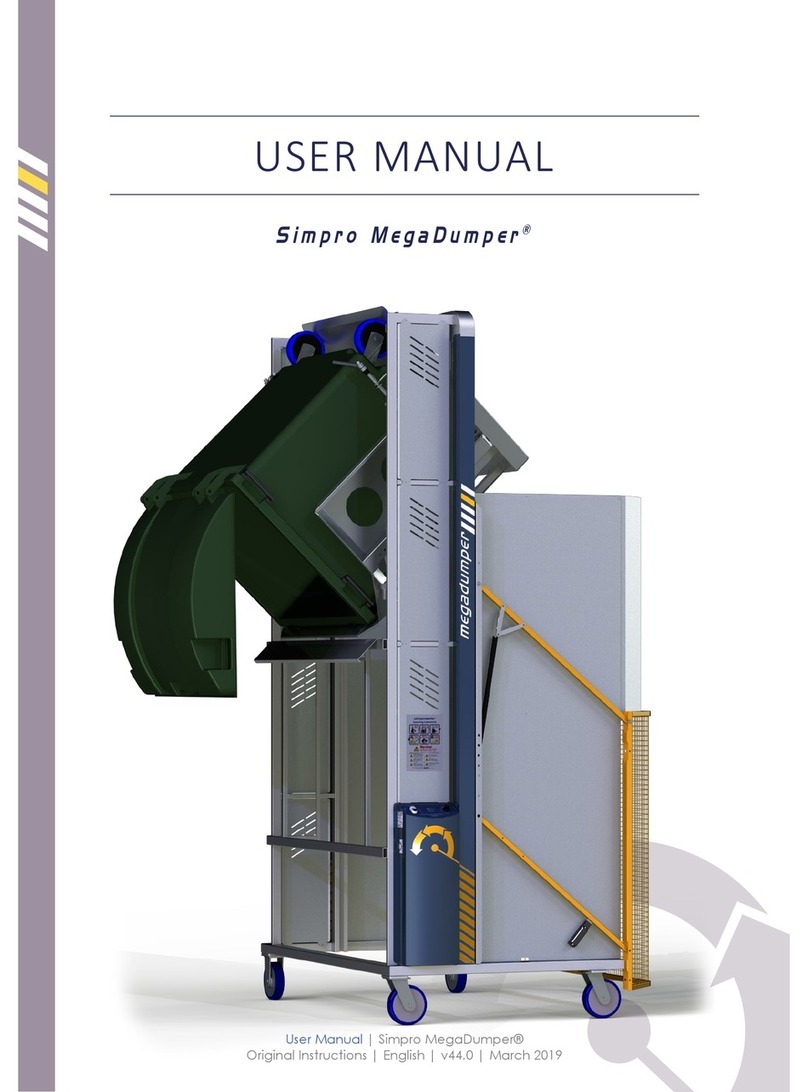
Simpro MegaDumper Series User manual
Simpro
Simpro MegaDumper User manual
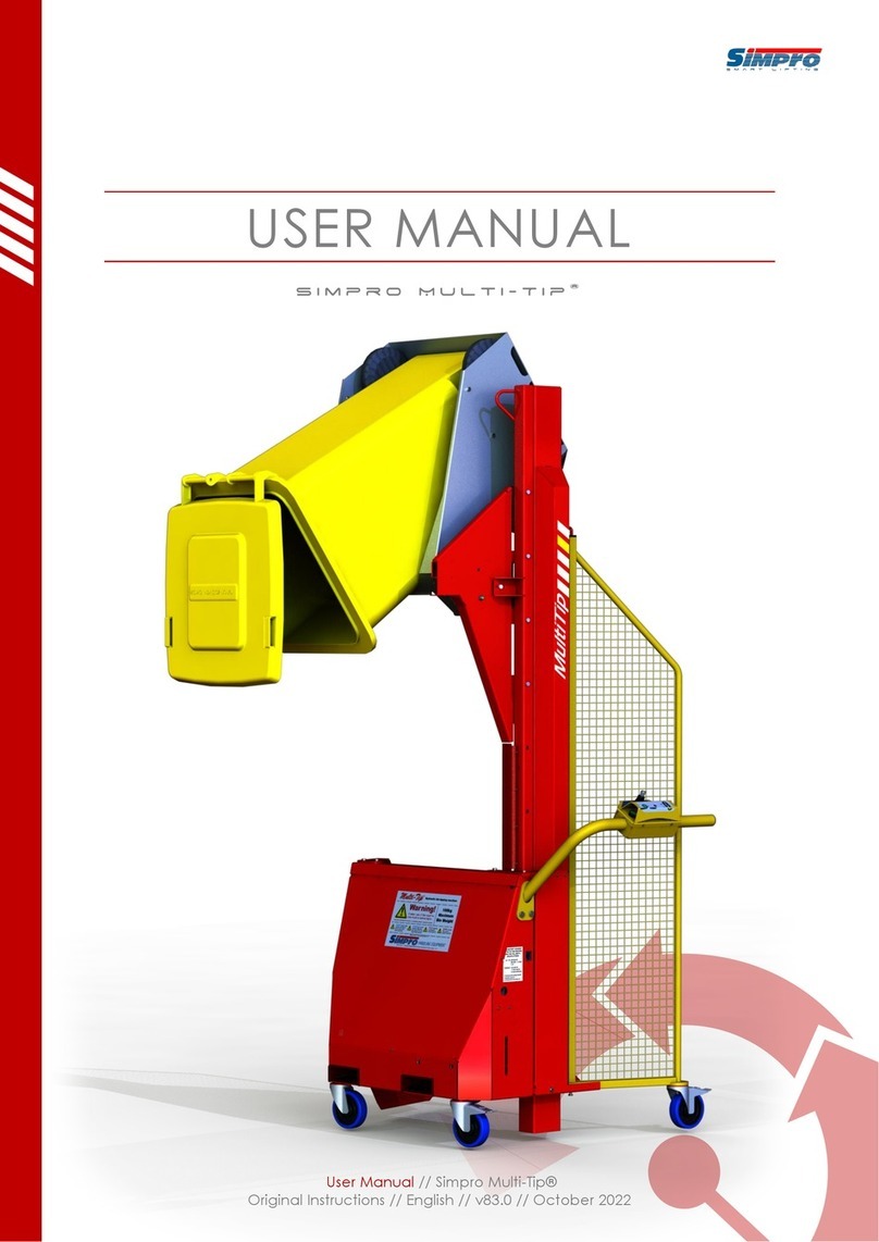
Simpro
Simpro Multi-Tip MT1200 User manual
Simpro
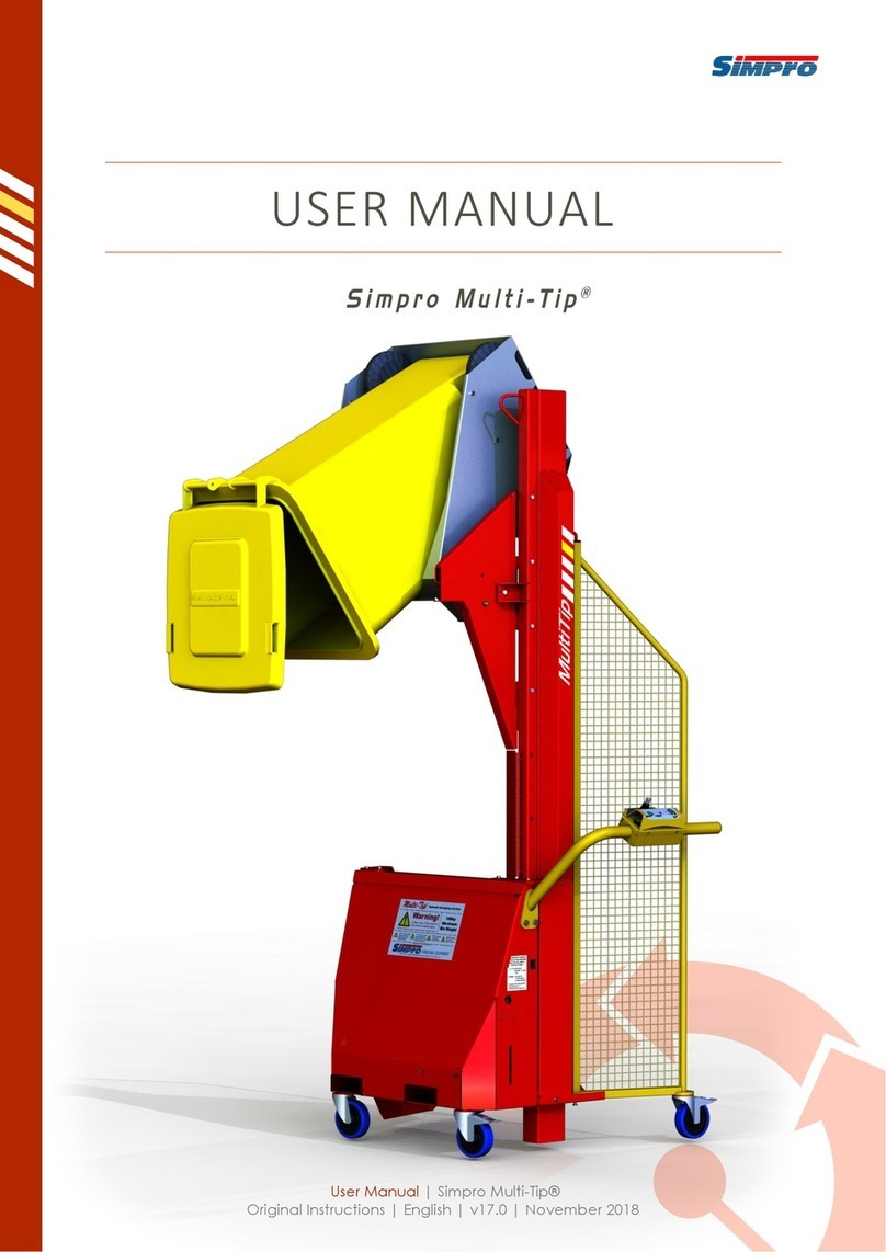
Simpro Multi-Tip User manual

Simpro
Simpro QUIKSTAK QS10MM User manual
Simpro
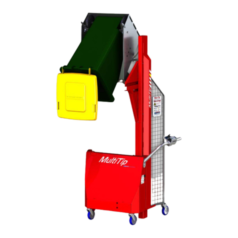
Simpro Multi-Tip 1600 User manual
Simpro
Simpro Multi-Tip User manual
Simpro
Simpro Dumpmaster User manual
Popular Lifting System manuals by other brands
morse
morse Hydra-Lift 400A-60 Operator's manual
Challenger Lifts
Challenger Lifts 40200 Operation installation maintenance manual

Floe
Floe VSD7500 owner's manual

Terex
Terex Genie S-40XC Service and repair manual
Ravaglioli
Ravaglioli RAV1140 Translation of the original instructions
Stratus
Stratus SAE-C10C Installation & operation
