Shoremaster Infinity RS4 User manual
INFINITY RS4 DOCK SYSTEM
PRODUCT ASSEMBLY INSTRUCTIONS
CAUTION - PUT SAFETY FIRST
RS4 INFINITY DOCK
Instructions and Safety Tips
Bolt Bag Part #: 1004425
4 x 4 Section Part #: 1004214
4 x 10 Section Part #: 1005986
4 x 12 Section Part #: 1005987
6 x 8 Section Part #: 1005989
3ft Dock Corner Part #: 1005990
45° Curved Dock Part #: 1003953
90° Curved Dock Part #: 1003954
CAUTION - PUT SAFETY FIRST
Before attempting to install or use this dock, study and fully understand the proper operating procedures and safety precautions
outlined in this owner's manual. If you have any questions about assembly, installation, use or suitability of this product, contact
an authorized dealer.
▪ NOT COMPLYING WITH THE PROCEDURES AND PRECAUTIONS OUTLINED IN THIS MANUAL WILL INVALIDATE THE
WARRANTY AND MAY RESULT IN PERSONAL INJURY OR DEATH.
▪ Be sure your dock can be installed on a firm and stable foundation. If lake bottom does not allow for a secure installation, this
product may not be suitable. ShoreMaster builds a wide variety of docks. Call your dealer for suggestions or other options.
▪ Install high enough above water surface, so waves do not contact Dock Frames or Panels.
▪ Do not dropped parts in the water. Please remove any Leg Caps or other parts from lake bottom to avoid injury.
▪ Do not run on dock. Running on dock could result in a falling injury. Use caution, especially when surface is wet.
▪ Do not dive off dock. Diving off dock could result in a severe head, neck, or back injury or death.
▪
Read and fully understand each step before proceeding with that step.
▪
Wear protective gloves, clothing and eyewear when assembling and installing the dock.
▪
Do not assemble, install or use this product if items are missing or damaged.
RS4 INFINITY DOCK
Instructions and Safety Tips
Bolt Bag Part #: 1004425
4 x 4 Section Part #: 1004214
4 x 10 Section Part #: 1005986
4 x 12 Section Part #: 1005987
6 x 8 Section Part #: 1005989
3ft Dock Corner Part #: 1005990
45° Curved Dock Part #: 1003953
90° Curved Dock Part #: 1003954
CAUTION - PUT SAFETY FIRST
Before attempting to install or use this dock, study and fully understand the proper operating procedures and safety precautions
outlined in this owner's manual. If you have any questions about assembly, installation, use or suitability of this product, contact
an authorized dealer.
▪ NOT COMPLYING WITH THE PROCEDURES AND PRECAUTIONS OUTLINED IN THIS MANUAL WILL INVALIDATE THE
WARRANTY AND MAY RESULT IN PERSONAL INJURY OR DEATH.
▪ Be sure your dock can be installed on a firm and stable foundation. If lake bottom does not allow for a secure installation, this
product may not be suitable. ShoreMaster builds a wide variety of docks. Call your dealer for suggestions or other options.
▪ Install high enough above water surface, so waves do not contact Dock Frames or Panels.
▪ Do not dropped parts in the water. Please remove any Leg Caps or other parts from lake bottom to avoid injury.
▪ Do not run on dock. Running on dock could result in a falling injury. Use caution, especially when surface is wet.
▪ Do not dive off dock. Diving off dock could result in a severe head, neck, or back injury or death.
▪ Read and fully understand each step before proceeding with that step.
▪ Wear protective gloves, clothing and eyewear when assembling and installing the dock.
▪ Do not assemble, install or use this product if items are missing or damaged.

2 | SHOREMASTER.COM
TABLE OF CONTENT
*RS4 Bundle*
DESCRIPTION
PART NUMBER
QTY
ITEM
Frame 4 x 10100368718
Frame 4 x 4
10036951
(8)
Frame 4 x 1210036881
(8)
Frame 6 x 810038081
(8)
Foot Pad 100652329
Bolt Bag - Listed at Left
10044251
-
Infinity Dock Pocket
100659121 0
*1004425 - Bolt Bag - RS-4 Dock System*
DESCRIPTION
PART NUMBER
QTY
ITEM
T-Handle 3/8 x 1.5
100087621
Connector Clip
100465122
Nut 3/8 Brass
100180323
Bolt Carriage 3/8 X 1.0
100195624
Nut Flange 3/8
10018022
5
Blue Cap
100181526
Corner Cap
10008754
7
Infinity Dock System
RS4 Section
Part Numbers:
4 x 4 Section - 1004214
4 x 10 Section - 1005986
4 x 12 Section - 1005987
6 x 8 Section - 1005989
Decking Type 2' PANELS 1' PANELS
Cedar Wood Deck 1007557
Plain Aluminum Deck 1007546
Ipe Hardwood Deck 1007564
White Aluminum Deck 1007567
Tan Aluminum Deck 1003442
Tan Vertex Deck 1004074
Titan Deck 1024039 1021586
LEG POSTS PART #
3' DOCK LEG POST (each) - 1003556
5' DOCK LEG POST (each) - 1000157
7' DOCK LEG POST (each) - 1000158
9' DOCK LEG POST (each) - 1000159
12' DOCK LEG POST (each) - 1000160
PARTS LIST "A" PARTS LIST "B"
7
A
2
A
1
A
3
A
6
A
8
B
LEGS SOLD SEPERATELY
(CHOICE OF SIZE - 3', 5',
7', 9', AND 12')
4
A5
A
10
B
9
B
Table of Contents................................................................................................................................................................................2
Parts and Components...................................................................................................................................................................3-4
Assembly Instructions.................................................................................................................................................................5-8
Common DockAccessories................................................................................................................................................................9
Accessory Installation...............................................................................................................................................................10-24
Warranty Information................................................................................................................................................................25-27
Installation Tools Needed:
DETAIL A
A
ASSEMBLY INSTRUCTIONS
Your safety is the most important issue related to this product.
Fully read and understand each step before proceeding with that step.
Wear protective gloves, clothing and eyewear when assembling and installing the lift.
Do not assemble, install or use this product if items are missing or damaged.
Leave all hardware finger tight until lift is completely assembled, then tighten all hardware.
For ease of assembly find a flat area with plenty of room to assemble lift. The following tools will be
needed for assembling lift:
1. 7/16" Wrench 5. Tin Snips (to open bundle)
2. Two 9/16" Wrenches 6. Vise Grip
3. Measuring Tape 7. Hammer
4. Sharp Knife or Razor 8. Square
STEP 1
Slide Blue Caps on uprights as shown. Insert all four Leg Posts into Foot Pads, secure using one 3/8
x 2 3/4 Hex Bolt and one 3/8 Brass Nut in each place. Insert Leg Posts into V-Side Lift and Opposite
Lift Side as shown. Use one 3/8 x 2 3/4 Hex Bolt, two 3/8 Flat Washers and one 3/8 Brass Nut for
each Leg Post.
Blue Cap
Foot Pad
Leg Post
Lift Side
3/8 Brass Nut
3/8 Flat Washer
3/8 x 3.0 Hex Bolt
3/8 x 2 3/4 Hex Bolt
3/8 Brass Nut
Lift Opposite Side
V-Side

SHOREMASTER.COM | 3
PARTS & COMPONENTS
PARTS & COMPONENTS
*RS4 Bundle*
DESCRIPTION
PART NUMBER
QTY
ITEM
Frame 4 x 10100368718
Frame 4 x 4
10036951
(8)
Frame 4 x 1210036881
(8)
Frame 6 x 810038081
(8)
Foot Pad 100652329
Bolt Bag - Listed at Left
10044251
-
Infinity Dock Pocket
100659121 0
*1004425 - Bolt Bag - RS-4 Dock System*
DESCRIPTION
PART NUMBER
QTY
ITEM
T-Handle 3/8 x 1.5
100087621
Connector Clip
100465122
Nut 3/8 Brass
100180323
Bolt Carriage 3/8 X 1.0
100195624
Nut Flange 3/8
10018022
5
Blue Cap
100181526
Corner Cap
10008754
7
Infinity Dock System
RS4 Section
Part Numbers:
4 x 4 Section - 1004214
4 x 10 Section - 1005986
4 x 12 Section - 1005987
6 x 8 Section - 1005989
Decking Type 2' PANELS 1' PANELS
Cedar Wood Deck 1007557
Plain Aluminum Deck 1007546
Ipe Hardwood Deck 1007564
White Aluminum Deck 1007567
Tan Aluminum Deck 1003442
Tan Vertex Deck 1004074
Titan Deck 1024039 1021586
LEG POSTS PART #
3' DOCK LEG POST (each) - 1003556
5' DOCK LEG POST (each) - 1000157
7' DOCK LEG POST (each) - 1000158
9' DOCK LEG POST (each) - 1000159
12' DOCK LEG POST (each) - 1000160
PARTS LIST "A" PARTS LIST "B"
7
A
2
A
1
A
3
A
6
A
8
B
LEGS SOLD SEPERATELY
(CHOICE OF SIZE - 3', 5',
7', 9', AND 12')
4
A5
A
10
B
9
B

4 | SHOREMASTER.COM
PARTS & COMPONENTS
Parts List
DESCRIPTION
PART NUMBER
QTY
ITEM
Frame 90 (RS4) Curve Dock
100369011
Panel Curve Dock 90 deg
100421112
Bolt Bag 45/90 RS4 Curve Dock
10044261
-
T Handle 3/8-16 x 1.5x2.5 w/ Cup Point
100087623
Nut Flange 3/8-16 Alum
10018022
4
Nut Hex 3/8-16 Brass
10018032
5
QC Dock Connector - 1.5
100465126
Bolt Carriage 3/8-16 x 1.0 SS 304
10019562
7
Plastic Cap w/ Logo - for Dock Pockets
1000875
4
8
Parts List
DESCRIPTION
PART NUMBER
QTY
ITEM
Uni-Dock Corner Frame 2005
100377911
Bolt Bag Corner RS4
10044271
-
T Handle 3/8-16 x 1.5x2.5 w/ Cup Point
100087642
Nut Flange 3/8-16 Alum
100180243
Nut Hex 3/8-16 Brass
100180344
QC Dock Connector - 1.5
10046514
5
Bolt Carriage 3/8-16 x 1.0 SS 304
100195646
Corner Panel
-
1
7
Parts List
DESCRIPTION
PART NUMBER
QTY
ITEM
Panel Curve Dock 45 deg
-
11
Bolt Bag 45/90 RS4 Curve Dock
10044261
-
T Handle 3/8-16 x 1.5 x 2.5 w/ Cup Point
100087622
Nut Flange 3/8-16 Alum
100180223
Nut Hex 3/8-16 Brass
10018032
5
QC Dock Connector - 1.5
100465126
Bolt Carriage 3/8-16 x 1.0 SS 304
100195626
Plastic Cap w/ Logo - for Dock Pockets
10008754
7
Wdmt Frame 45 Degree Curve Dock RS4
100368918
RS4 Dock Corner - 3ft
Part #: 1005990
1
6
5
3
4
2
RS4 Curved Dock - 45º
Part #: 1003953
RS4 Curved Dock - 90º
Part #: 1003954
7
8
6
5
6
2 3
1
8
7
5
364
7
1
2
A
Parts List
DESCRIPTION
PART NUMBER
QTY
ITEM
T Handle 2.5 - 3/8 x 1.25
100087641
Nut Flange 3/8
1001802
4
2
NUT 3/8
100180343
Connector Clip
1004651
44
Bolt Carriage 3/8 X 1.0
10019564
5
Assembly:
Place one 3/8 Nut in each Connector Clip nut holder and thread the 2 1/2 - 3/8 x 1 1/4 T-Handle
through it just enough so that it does not fall out.
Attach two Connector Clips to each dock frame that will be supporting the Corner Frame. Secure to
dock frame with one 3/8 x 1 Carriage Bolt and one 3/8 Flange Nut in each place - as shown.
Place the Corner Frame into the Connector Clips and tighten each 2 1/2 - 3/8 x 1 1/4 T-Handle
against the Corner Frame until it is secure against the supporting dock frames.
Place Corner Panel in frame.
2
3
1
4
5
Infinity Dock System
Corner Bolt Bag
Part #: 1004427 (Dock corner)
Part #: 1004426 (Dock Corner Curve)
(RS4, RS7, & TS9)
SHOREMASTER.COM | 5
CORNER BOLT BAG
CORNER BOLT BAG
Parts List
DESCRIPTION
PART NUMBER
QTY
ITEM
Frame 90 (RS4) Curve Dock
100369011
Panel Curve Dock 90 deg
100421112
Bolt Bag 45/90 RS4 Curve Dock
10044261
-
T Handle 3/8-16 x 1.5x2.5 w/ Cup Point
100087623
Nut Flange 3/8-16 Alum
10018022
4
Nut Hex 3/8-16 Brass
10018032
5
QC Dock Connector - 1.5
100465126
Bolt Carriage 3/8-16 x 1.0 SS 304
10019562
7
Plastic Cap w/ Logo - for Dock Pockets
1000875
4
8
Parts List
DESCRIPTION
PART NUMBER
QTY
ITEM
Uni-Dock Corner Frame 2005
100377911
Bolt Bag Corner RS4
10044271
-
T Handle 3/8-16 x 1.5x2.5 w/ Cup Point
100087642
Nut Flange 3/8-16 Alum
100180243
Nut Hex 3/8-16 Brass
100180344
QC Dock Connector - 1.5
10046514
5
Bolt Carriage 3/8-16 x 1.0 SS 304
100195646
Corner Panel
-
1
7
Parts List
DESCRIPTION
PART NUMBER
QTY
ITEM
Panel Curve Dock 45 deg
-
11
Bolt Bag 45/90 RS4 Curve Dock
10044261
-
T Handle 3/8-16 x 1.5 x 2.5 w/ Cup Point
100087622
Nut Flange 3/8-16 Alum
100180223
Nut Hex 3/8-16 Brass
10018032
5
QC Dock Connector - 1.5
100465126
Bolt Carriage 3/8-16 x 1.0 SS 304
100195626
Plastic Cap w/ Logo - for Dock Pockets
10008754
7
Wdmt Frame 45 Degree Curve Dock RS4
100368918
RS4 Dock Corner - 3ft
Part #: 1005990
1
6
5
3
4
2
RS4 Curved Dock - 45º
Part #: 1003953
RS4 Curved Dock - 90º
Part #: 1003954
7
8
6
5
6
2 3
1
8
7
5
364
7
1
2
A
Parts List
DESCRIPTION
PART NUMBER
QTY
ITEM
T Handle 2.5 - 3/8 x 1.25
100087641
Nut Flange 3/8
1001802
4
2
NUT 3/8
100180343
Connector Clip
1004651
44
Bolt Carriage 3/8 X 1.0
10019564
5
Assembly:
Place one 3/8 Nut in each Connector Clip nut holder and thread the 2 1/2 - 3/8 x 1 1/4 T-Handle
through it just enough so that it does not fall out.
Attach two Connector Clips to each dock frame that will be supporting the Corner Frame. Secure to
dock frame with one 3/8 x 1 Carriage Bolt and one 3/8 Flange Nut in each place - as shown.
Place the Corner Frame into the Connector Clips and tighten each 2 1/2 - 3/8 x 1 1/4 T-Handle
against the Corner Frame until it is secure against the supporting dock frames.
Place Corner Panel in frame.
2
3
1
4
5
Infinity Dock System
Corner Bolt Bag
Part #: 1004427 (Dock corner)
Part #: 1004426 (Dock Corner Curve)
(RS4, RS7, & TS9)
F | SHOREMASTER.COM
ASSEMBLY INSTRUCTIONS
DETAIL B
DETAIL A
B
A
Tools needed:
1. 9/16” Wrench
2. Measuring Tape
3. Optional - Carpenter's Level
Tips:
Before assembly determine the layout of the dock system.
Take depth measurements at ten foot intervals starting at
where the dock will start.
Have adequete dock leg lengths to accommodate water
fluctuation and waves.
For ease of assembly find a flat area with sufficient room to
assemble dock.
STEP 1
After determining the layout of your Dock System, install all
Leg Pockets according to their instructions. The number and
location of Leg Pockets will depend on the specific layout
and the type of Leg Posts.
STEP 2
Attach one Foot Pad to each Leg Post. Secure Leg Post with
one 1/2 x 1 1/4 Set Screw and one 1/2 Square Nut per leg.
Note: Leg Posts are ordered separately from dock section
because of varying lengths needed.
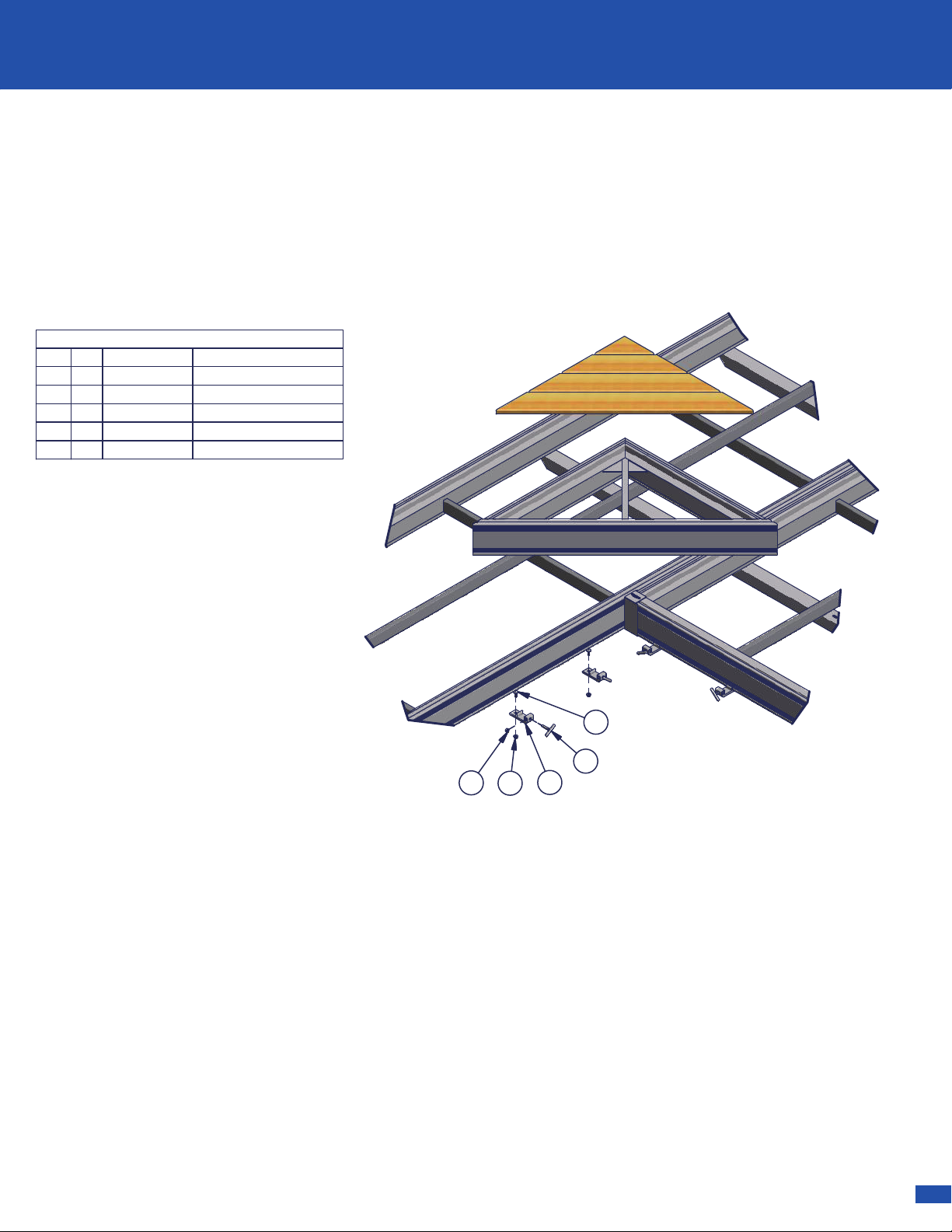
STEP 3
Determine which side of the RS4 Frame will be connected to
other sections. Insert one 3/8 Nut into each Connector Clip
and thread the 3/8 x 1 1/2 T-Handle through it just so they
stay together - as shown in Detail "A".
Attach Connector Clips to the Rail. Secure with one 3/8 x 1
Carriage Bolt and one 3/8 Flange Nut. The Carriage Bolt
head inserts into the opening in the bottom slot of the Rail
and attaches to the Connector Clip - as shown in Detail "A".
Place the Connector Clip six inches or less in from the
Corner - as shown in Detail "B".
NOTICE: A Rail six feet or less requires two Connector
Clips. Rails greater than Six feet need a third connector in
the middle of the connection.
CAUTION: Make sure the Connector Clip
assembly is fully clear of the Opening in the slot.
Corner
Connector Clip
6"
ASSEMBLY INSTRUCTIONS
3/8 Nut
T-Handle
Connector
Clip
3/8 Flange Nut
T-Handle
DETAIL A
D
E
A
G
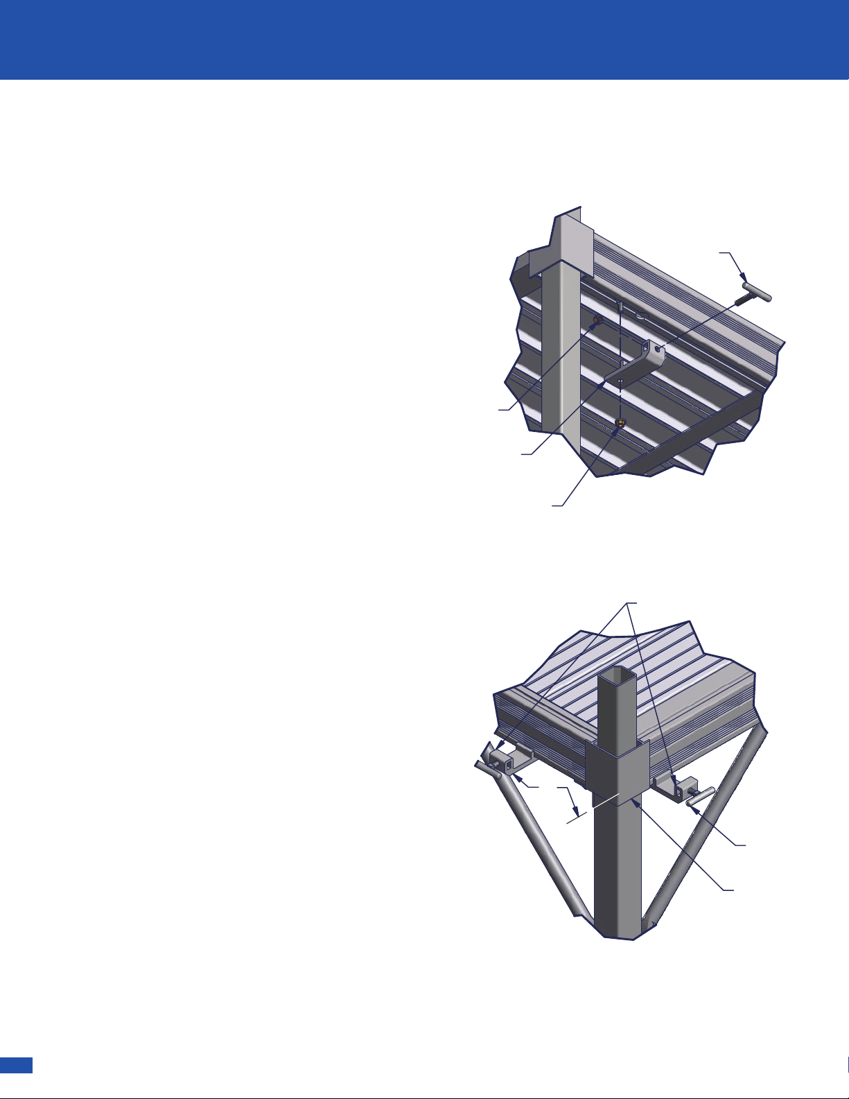
STEP 4
Now the first Frame can be carried into place. Place the second
Frame into the Connector Clips of the first - as shown to the
right.
CAUTION:
The Connector Clips must be bolted to a dock
frame that is supported by legs. The unsupported end of the
attaching dock frame will set into the Connector Clip.
Secure by tightening the 3/8 x 1 1/2 T-Handle - as shown in
Detail "A."
Note: Two Connector Clips are needed if connecting to an End
Rail. Three are needed if connecting two Side Rails together.
Supported Frame
Unsupported Frame
Supported Frame
Unsupported Frame
Good Connection
Bad Connection
Connector Clip
3/8 x 1 1/2 T-Handle
Connector Clip
Connector Clip
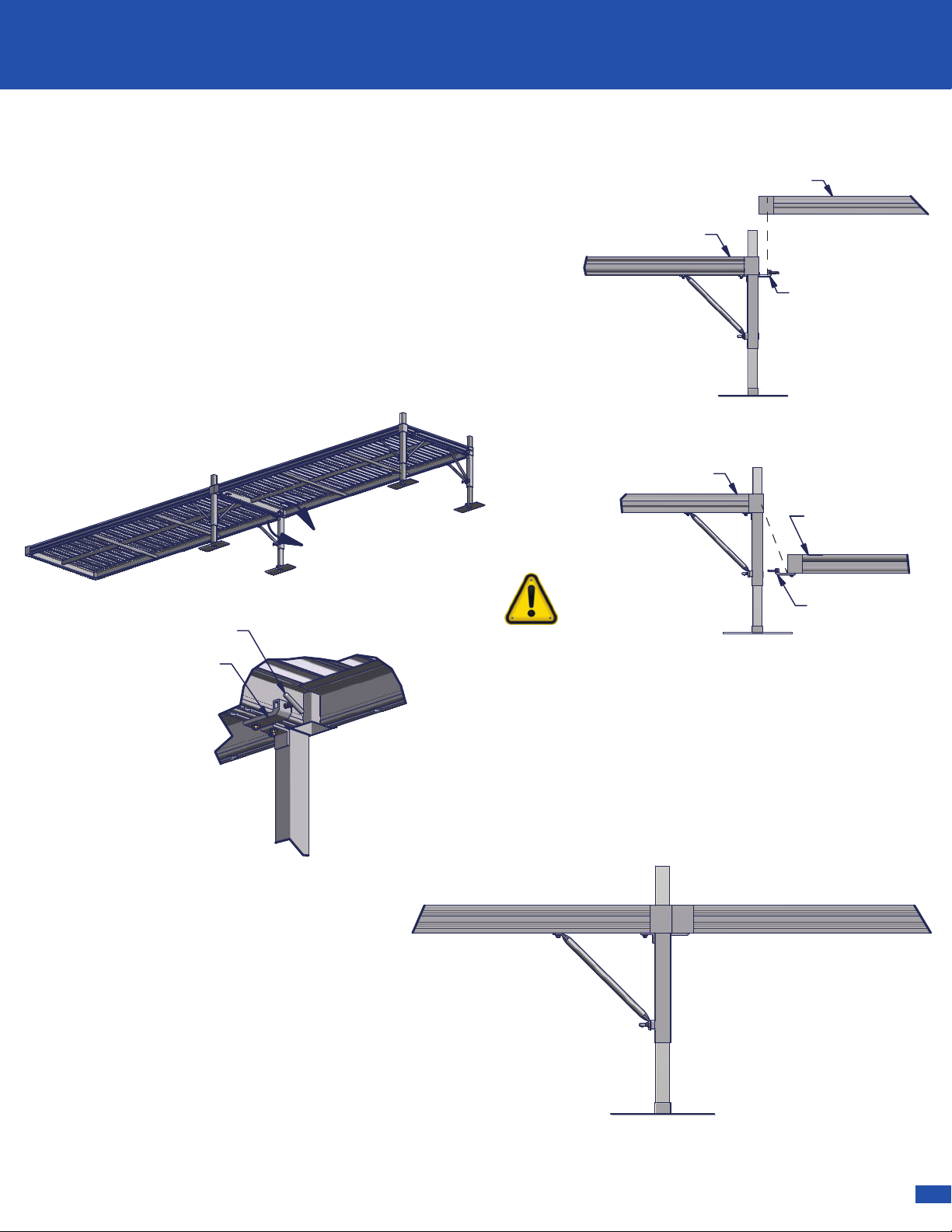
STEP 5
When all RS4 Frames are in place, adjust
the level of the dock sections as needed
using the adjustable leg posts.
Note: Make sure there is enough
clearance for water flucuation and wave
action.
Fully tighten all Nuts and Bolts.
Note: Do not over tighten set screws. Over
tightening of set screws will result in
bending or breaking of parts.
!
SHOREMASTER.COM | G
ASSEMBLY INSTRUCTIONS
ASSEMBLY INSTRUCTIONS
DETAIL B
DETAIL A
B
A
Tools needed:
1. 9/16” Wrench
2. Measuring Tape
3. Optional - Carpenter's Level
Tips:
Before assembly determine the layout of the dock system.
Take depth measurements at ten foot intervals starting at
where the dock will start.
Have adequete dock leg lengths to accommodate water
fluctuation and waves.
For ease of assembly find a flat area with sufficient room to
assemble dock.
STEP 1
After determining the layout of your Dock System, install all
Leg Pockets according to their instructions. The number and
location of Leg Pockets will depend on the specific layout
and the type of Leg Posts.
STEP 2
Attach one Foot Pad to each Leg Post. Secure Leg Post with
one 1/2 x 1 1/4 Set Screw and one 1/2 Square Nut per leg.
Note: Leg Posts are ordered separately from dock section
because of varying lengths needed.
STEP 3
Determine which side of the RS4 Frame will be connected to
other sections. Insert one 3/8 Nut into each Connector Clip
and thread the 3/8 x 1 1/2 T-Handle through it just so they
stay together - as shown in Detail "A".
Attach Connector Clips to the Rail. Secure with one 3/8 x 1
Carriage Bolt and one 3/8 Flange Nut. The Carriage Bolt
head inserts into the opening in the bottom slot of the Rail
and attaches to the Connector Clip - as shown in Detail "A".
Place the Connector Clip six inches or less in from the
Corner - as shown in Detail "B".
NOTICE: A Rail six feet or less requires two Connector
Clips. Rails greater than Six feet need a third connector in
the middle of the connection.
CAUTION: Make sure the Connector Clip
assembly is fully clear of the Opening in the slot.
Corner
Connector Clip
6"
ASSEMBLY INSTRUCTIONS
3/8 Nut
T-Handle
Connector
Clip
3/8 Flange Nut
T-Handle
DETAIL A
D
E
A
G
STEP 4
Now the first Frame can be carried into place. Place the second
Frame into the Connector Clips of the first - as shown to the
right.
CAUTION:
The Connector Clips must be bolted to a dock
frame that is supported by legs. The unsupported end of the
attaching dock frame will set into the Connector Clip.
Secure by tightening the 3/8 x 1 1/2 T-Handle - as shown in
Detail "A."
Note: Two Connector Clips are needed if connecting to an End
Rail. Three are needed if connecting two Side Rails together.
Supported Frame
Unsupported Frame
Supported Frame
Unsupported Frame
Good Connection
Bad Connection
Connector Clip
3/8 x 1 1/2 T-Handle
Connector Clip
Connector Clip
STEP 5
When all RS4 Frames are in place, adjust
the level of the dock sections as needed
using the adjustable leg posts.
Note: Make sure there is enough
clearance for water flucuation and wave
action.
Fully tighten all Nuts and Bolts.
Note: Do not over tighten set screws. Over
tightening of set screws will result in
bending or breaking of parts.
!

H | SHOREMASTER.COM
ASSEMBLY INSTRUCTIONS
STEP 6
Leg Caps are included for each Corner Tube that is
not used or does not have a Leg Post above the deck
surface - as shown below.
The Leg Posts that are above the deck surface may
be covered with a Blue Cap - as shown below.
Leg Cap
Blue Cap
USE, REMOVAL, STORAGE AND SERVICE
▪Upon completed installation, your RS-4 Dock System is ready for use. Many ShoreMaster dock accessories are
available to compliment your dock system. Contact your dealer for available options.
NOTICE: The dock system must be removed from water during the winter months. Warranty is void if dock is exposed
to ice conditions.
▪You may remove each frame with panels in place, or you can remove the panels before detaching the frames. Stack
panels on a flat surface, and store them in a dry area to preserve life.
▪Inspect frames, panels, connections, nuts, and bolts at least once every six months for damage, wear or loose
connections. Tighten or replace parts as needed.
▪ShoreMaster dealers usually offer service visits. Please contact them if you are unable or unwilling to perform service to
docks.
Common Dock Accessories
- QC 4-Step Dock
- QC Pivoting Ladder
- QC LakeView Rhino Bench (Off Deck)
- LakeView Rhino Bench (On Deck)
- LakeView Bench Armrest
- Furniture Hardware Box
- QC Umbrella Holder
- QC Flagpole Holder
- QC Fishing Rod Holder
- QC Cleat Kit
- QC Vertical Roto Bumper
- QC Canoe/Kayak Rack
- Wheel/Axle Adapter for 2 x 2 Dock Legs
- Single Leg Pocket
- QC Leg Pocket Add-On Bracket

SHOREMASTER.COM | 9
COMMON DOCK ACCESSORIES
COMMON DOCK ACCESSORIES
STEP 6
Leg Caps are included for each Corner Tube that is
not used or does not have a Leg Post above the deck
surface - as shown below.
The Leg Posts that are above the deck surface may
be covered with a Blue Cap - as shown below.
Leg Cap
Blue Cap
USE, REMOVAL, STORAGE AND SERVICE
▪Upon completed installation, your RS-4 Dock System is ready for use. Many ShoreMaster dock accessories are
available to compliment your dock system. Contact your dealer for available options.
NOTICE: The dock system must be removed from water during the winter months. Warranty is void if dock is exposed
to ice conditions.
▪You may remove each frame with panels in place, or you can remove the panels before detaching the frames. Stack
panels on a flat surface, and store them in a dry area to preserve life.
▪Inspect frames, panels, connections, nuts, and bolts at least once every six months for damage, wear or loose
connections. Tighten or replace parts as needed.
▪ShoreMaster dealers usually offer service visits. Please contact them if you are unable or unwilling to perform service to
docks.
Common Dock Accessories
- QC 4-Step Dock
- QC Pivoting Ladder
- QC LakeView Rhino Bench (Off Deck)
- LakeView Rhino Bench (On Deck)
- LakeView Bench Armrest
- Furniture Hardware Box
- QC Umbrella Holder
- QC Flagpole Holder
- QC Fishing Rod Holder
- QC Cleat Kit
- QC Vertical Roto Bumper
- QC Canoe/Kayak Rack
- Wheel/Axle Adapter for 2 x 2 Dock Legs
- Single Leg Pocket
- QC Leg Pocket Add-On Bracket

10 | SHOREMASTER.COM
ACCESSORY INSTALLATION
Parts List
DESCRIPTION
PART NUMBER
QTY
ITEM
Step
100454941
Bottom Upright 32.0 100498522
Top Upright 34.0 100498923
Leg
10056792
4
Left Stringer
10037841
5
Right Stringer
100378316
Handrail 4 Step
10038442
7
Bolt Bag
10044421
-
Nut 1/4
10017971 68
Nut 3/8
100180389
Carriage Bolt 1/4 x .75
10019501610
Bolt 3/8 x 2.0
100242441 1
Bolt 3/8 x 3.0
100243241 2
Press-In Cap
100098641 3
4
12
2
3
11
6
5
9
8
1
10
11
9
7
12
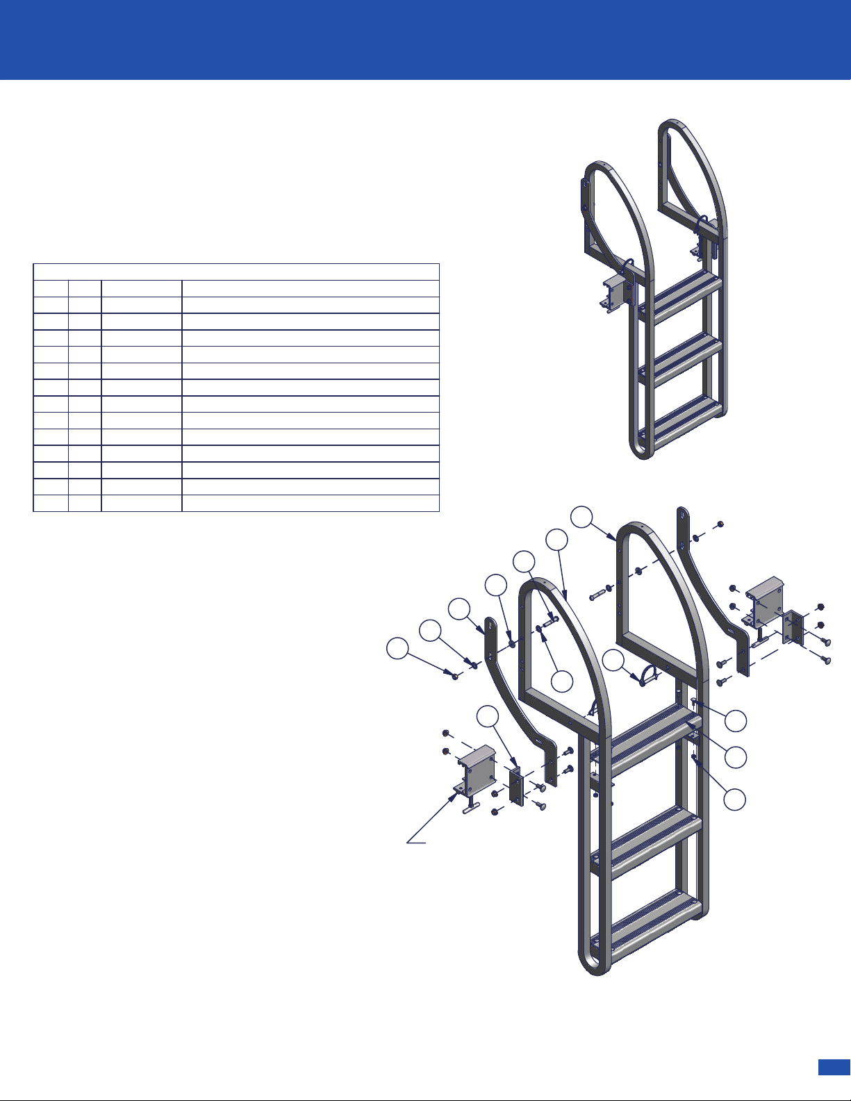
QC 4-Step Dock Steps
Instructions
Part #: 1004263
Note: There are three different types of accessory brackets that
the steps can be attached to in order to be attached to your
dock. You will need two accessory brackets for the installation.
Below is a list of the three different types of brackets.
Note: In order to attach dock steps to a dock not listed above
use two 3/8" x 3-1/2" carriage bolts and two 3/8" flange nuts
(provided).
13
Step 1.
Attach steps to right and left stringer using 1/4" x 3/4"
Carriage Bolts and 1/4" Nuts provided.
Step 2
. Insert top uprights into top pockets of stringer and
secure on the bottom using 3/8" x 3" Bolts and 3/8" Hex Nuts.
Step 3
. Insert bottom uprights into bottom pockets of stringers,
fully insert legs into stringer pockets and bottom uprights, secure
the uprights and legs using 3/8" x 3" Hex Bolt and 3/8" Hex Nut.
(adjust height of legs after connecting stairs to dock frame.)
Step 4
. Connect stairs to QC accessory brackets using Carriage
Bolts and Nuts. (see QC accessory bracket instructions)
Dock Type Bracket Part Number
RS4 Dock 1006706
RS7 Dock 1006708
TS9 Dock 1006730
3 Step Ladder Shown
DESCRIPTION
PART NUMBER
QTY
ITEM
Ladder Pivot Bracket
100093221
Ladder Frame Left
100561512
Ladder Frame Right
100561613
Ladder Step
100578534
Ladder Pivot Angle
10027962
5
Bolt Bag (4 Step = 1004453, 5 Step = 1000522)
10044521
-
Nut 1/4 (4 step = qty 16, 5 step = qty 20)
10017971 26
Bolt Carriage 1/4 x 3/4 (4 step = qty 16, 5 step = qty 20)
100195012
7
Pin Snap 3/8 x 1.75
100033828
Bolt Slotted Round 3/8 x 2.0
100259329
Washer Flat 3/8
1002599
4
10
Plastic Spacer
100246921 1
Nut Nyloc 3/8-16 Brass
100180521 2
QC Pivoting Ladder
Instructions
Part #: 1006669 QC Pivoting Ladder 3 Step
Part #: 1006670 QC Pivoting Ladder 4 Step
Part #: 1006671 QC Pivoting Ladder 5 Step
Step 1
. Attach each Ladder Pivot Angle to
one Ladder Pivot Bracket and one
Accessory Connector (Sold Separately).
Secure to each with two 3/8 x 1 Carriage
Bolts and two 3/8 Flange Nuts (included with
Accessory Connector Kit) - as shown.
Step 2
. Attach each Ladder Step to the
Ladder Frame Left and the Ladder Frame
Right. Secure to Ladder Frame with two 1/4
Carriage Bolts and two 1/4 Nuts - as shown.
Step 3
. Attach the Ladder Frame Right and
Ladder Frame Left each to one Ladder Pivot
Bracket. Secure with one 3/8 x 2 Round
Slotted Bolt, two Poly Spacers, two 3/8 Flat
Washers, and one 3/8 Nyloc Nut - as shown.
Note: While the ladder is in use, secure it
down with two Snap Pins - as shown.
3
1
6
4
7
10
8
Quick-Connect Bracket
(Sold Separately)
1006706 - RS4
1006708 - RS7
1006730- TS9
5
11
2
9
10
12
SHOREMASTER.COM | 11
ACCESSORY INSTALLATION
ACCESSORY INSTALLATION
Parts List
DESCRIPTION
PART NUMBER
QTY
ITEM
Step
100454941
Bottom Upright 32.0 100498522
Top Upright 34.0 100498923
Leg
10056792
4
Left Stringer
10037841
5
Right Stringer
100378316
Handrail 4 Step
10038442
7
Bolt Bag
10044421
-
Nut 1/4
10017971 68
Nut 3/8
100180389
Carriage Bolt 1/4 x .75
10019501610
Bolt 3/8 x 2.0
100242441 1
Bolt 3/8 x 3.0
100243241 2
Press-In Cap
100098641 3
4
12
2
3
11
6
5
9
8
1
10
11
9
7
12
QC 4-Step Dock Steps
Instructions
Part #: 1004263
Note: There are three different types of accessory brackets that
the steps can be attached to in order to be attached to your
dock. You will need two accessory brackets for the installation.
Below is a list of the three different types of brackets.
Note: In order to attach dock steps to a dock not listed above
use two 3/8" x 3-1/2" carriage bolts and two 3/8" flange nuts
(provided).
13
Step 1.
Attach steps to right and left stringer using 1/4" x 3/4"
Carriage Bolts and 1/4" Nuts provided.
Step 2
. Insert top uprights into top pockets of stringer and
secure on the bottom using 3/8" x 3" Bolts and 3/8" Hex Nuts.
Step 3
. Insert bottom uprights into bottom pockets of stringers,
fully insert legs into stringer pockets and bottom uprights, secure
the uprights and legs using 3/8" x 3" Hex Bolt and 3/8" Hex Nut.
(adjust height of legs after connecting stairs to dock frame.)
Step 4
. Connect stairs to QC accessory brackets using Carriage
Bolts and Nuts. (see QC accessory bracket instructions)
Dock Type Bracket Part Number
RS4 Dock 1006706
RS7 Dock 1006708
TS9 Dock 1006730
3 Step Ladder Shown
DESCRIPTION
PART NUMBER
QTY
ITEM
Ladder Pivot Bracket
100093221
Ladder Frame Left
100561512
Ladder Frame Right
100561613
Ladder Step
100578534
Ladder Pivot Angle
10027962
5
Bolt Bag (4 Step = 1004453, 5 Step = 1000522)
10044521
-
Nut 1/4 (4 step = qty 16, 5 step = qty 20)
10017971 26
Bolt Carriage 1/4 x 3/4 (4 step = qty 16, 5 step = qty 20)
100195012
7
Pin Snap 3/8 x 1.75
100033828
Bolt Slotted Round 3/8 x 2.0
100259329
Washer Flat 3/8
1002599
4
10
Plastic Spacer
100246921 1
Nut Nyloc 3/8-16 Brass
100180521 2
QC Pivoting Ladder
Instructions
Part #: 1006669 QC Pivoting Ladder 3 Step
Part #: 1006670 QC Pivoting Ladder 4 Step
Part #: 1006671 QC Pivoting Ladder 5 Step
Step 1
. Attach each Ladder Pivot Angle to
one Ladder Pivot Bracket and one
Accessory Connector (Sold Separately).
Secure to each with two 3/8 x 1 Carriage
Bolts and two 3/8 Flange Nuts (included with
Accessory Connector Kit) - as shown.
Step 2
. Attach each Ladder Step to the
Ladder Frame Left and the Ladder Frame
Right. Secure to Ladder Frame with two 1/4
Carriage Bolts and two 1/4 Nuts - as shown.
Step 3
. Attach the Ladder Frame Right and
Ladder Frame Left each to one Ladder Pivot
Bracket. Secure with one 3/8 x 2 Round
Slotted Bolt, two Poly Spacers, two 3/8 Flat
Washers, and one 3/8 Nyloc Nut - as shown.
Note: While the ladder is in use, secure it
down with two Snap Pins - as shown.
3
1
6
4
7
10
8
Quick-Connect Bracket
(Sold Separately)
1006706 - RS4
1006708 - RS7
1006730- TS9
5
11
2
9
10
12

12 | SHOREMASTER.COM
ACCESSORY INSTALLATION
Parts List
DESCRIPTION
PART NUMBER
QTY
ITEM
Bench Poly Plank Tan102299921
Off-Deck Lakeview Bench Frame
101308722
Bolt Bag Lakeview Bench QC
10130901
--
3/8" x 2" Hex Bolt
100242483
Washer Fender 3/8 x 1.5 SS
100260184
Plastic Push-In Cap
1000986
4
5
2
3
1
5
5
Step 1
. Attach off-deck bench frames to
bench poly planks using 3/8" Fender Washers
and 3/8" x 2" Hex Bolts. Do not over tighten
bolts.
Note: Make sure to attach bench poly planks
in the proper orientation - as shown.
Step 2
. Insert plastic push-in caps into
off-deck bench frames as shown.
Step 3
. Attach off-deck bench frames to dock
accessory connectors (sold separately)
according to accessory connector instructions.
4
QC LakeView Rhino Bench
(Off Deck) Tan
Instructions
Part #: 1022994
Front View
Rear View
Note: QC LakeView Rhino Bench will be attached
to one of four different type of Accessory Dock
Connectors in order to be attached to your dock.
Below is a list of the four different types of docks
and the required bracket.
Dock Type Bracket Part Number
RS4 Dock 1006706
RS7 Dock 1006708
RS9 Dock 1006730
Poly Dock 1006608
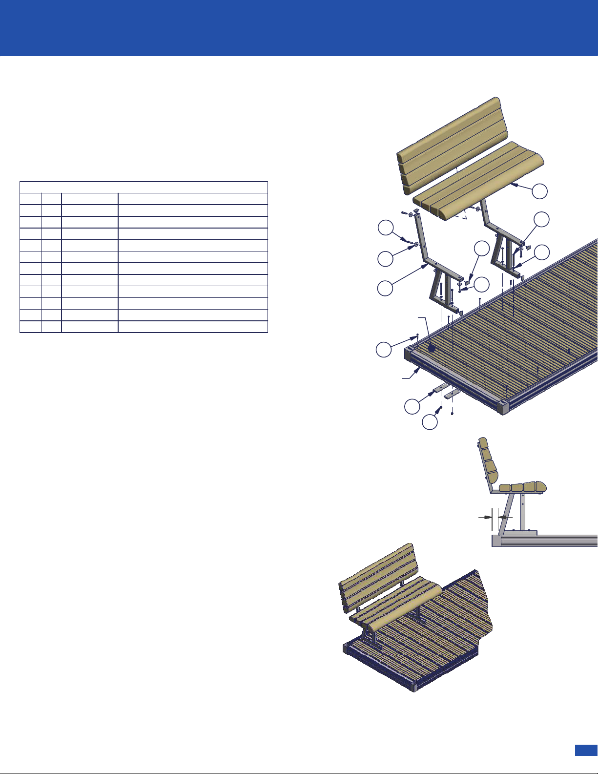
DETAIL H
SCALE 1/35
Detail-A
H
Parts List
DESCRIPTION
PART NUMBER
QTY
ITEM
Weldment Lakeview Bench Frame On-Deck
101308021
Prt Bench Plank Poly 3.5x16.35x48.0 Tan102299922
Bolt Bag Lakeview On-Deck Bench
10130841
--
Washer Flat 3/8 SS
1002599
4
3
Bolt Hex 3/8-16 x 2.0 SS 304
100242484
Cap Press-In 1.125 x 1.625 Silver W/Logo
10009866
5
Bolt Hex 3/8-16 x 4.5 Full Thread SS 304
100244246
Alum Plate 1/4" x 2" x 6" With 7/16" Hole
1004624
4
7
Washer Fender 3/8 x 1.5 SS
100260188
Nut Nyloc 3/8-16 Brass
1001805
4
9
Screw Pan Phil 1/4 x 1.75 T/A SS
100257681 0
2
7
10
6
5
4
2
1
Dock
Dock Panel
Step 1.
Attach bench planks to on-deck bench frames
using 3/8" Fender Washers and 3/8" x 2" Hex Bolts. Do
not over tighten bolts.
Note: Make sure to attach bench planks in the proper
orientation as shown.
Step 2.
Insert plastic push-in caps into on-deck bench
frames as shown.
Step 3.
Set bench on dock in desired position (2" from
edge of dock, as shown in Detail "A") and mark the four
mounting hole locations on the dock panel. Inspect
underside of dock panel to make sure you do not hit the
dock frame or other obstructions. Drill holes through
dock panel using a 7/16" drill bit.
Step 4.
Secure dock bench to dock panel using 3/8" x
4-1/2" Hex Bolts, 3/8" Flat Washers, Backer Plates and
3/8" Nyloc Nuts.
Step 5.
Secure dock panel to dock using 1/4" x 1-3/4"
Phillips Pan Wood Screws.
Note: Failure to secure dock panel to dock could result
in causing bodily injury or possible death.
4
83
9
LakeView Rhino Bench
On-Deck Tan
Instructions
Part #: 1023002
SHOREMASTER.COM | 13
ACCESSORY INSTALLATION
ACCESSORY INSTALLATION
Parts List
DESCRIPTION
PART NUMBER
QTY
ITEM
Bench Poly Plank Tan102299921
Off-Deck Lakeview Bench Frame
101308722
Bolt Bag Lakeview Bench QC
10130901
--
3/8" x 2" Hex Bolt
100242483
Washer Fender 3/8 x 1.5 SS
100260184
Plastic Push-In Cap
1000986
4
5
2
3
1
5
5
Step 1
. Attach off-deck bench frames to
bench poly planks using 3/8" Fender Washers
and 3/8" x 2" Hex Bolts. Do not over tighten
bolts.
Note: Make sure to attach bench poly planks
in the proper orientation - as shown.
Step 2
. Insert plastic push-in caps into
off-deck bench frames as shown.
Step 3
. Attach off-deck bench frames to dock
accessory connectors (sold separately)
according to accessory connector instructions.
4
QC LakeView Rhino Bench
(Off Deck) Tan
Instructions
Part #: 1022994
Front View
Rear View
Note: QC LakeView Rhino Bench will be attached
to one of four different type of Accessory Dock
Connectors in order to be attached to your dock.
Below is a list of the four different types of docks
and the required bracket.
Dock Type Bracket Part Number
RS4 Dock 1006706
RS7 Dock 1006708
RS9 Dock 1006730
Poly Dock 1006608
DETAIL H
SCALE 1/35
Detail-A
H
Parts List
DESCRIPTION
PART NUMBER
QTY
ITEM
Weldment Lakeview Bench Frame On-Deck
101308021
Prt Bench Plank Poly 3.5x16.35x48.0 Tan102299922
Bolt Bag Lakeview On-Deck Bench
10130841
--
Washer Flat 3/8 SS
1002599
4
3
Bolt Hex 3/8-16 x 2.0 SS 304
100242484
Cap Press-In 1.125 x 1.625 Silver W/Logo
10009866
5
Bolt Hex 3/8-16 x 4.5 Full Thread SS 304
100244246
Alum Plate 1/4" x 2" x 6" With 7/16" Hole
1004624
4
7
Washer Fender 3/8 x 1.5 SS
100260188
Nut Nyloc 3/8-16 Brass
1001805
4
9
Screw Pan Phil 1/4 x 1.75 T/A SS
100257681 0
2
7
10
6
5
4
2
1
Dock
Dock Panel
Step 1.
Attach bench planks to on-deck bench frames
using 3/8" Fender Washers and 3/8" x 2" Hex Bolts. Do
not over tighten bolts.
Note: Make sure to attach bench planks in the proper
orientation as shown.
Step 2.
Insert plastic push-in caps into on-deck bench
frames as shown.
Step 3.
Set bench on dock in desired position (2" from
edge of dock, as shown in Detail "A") and mark the four
mounting hole locations on the dock panel. Inspect
underside of dock panel to make sure you do not hit the
dock frame or other obstructions. Drill holes through
dock panel using a 7/16" drill bit.
Step 4.
Secure dock bench to dock panel using 3/8" x
4-1/2" Hex Bolts, 3/8" Flat Washers, Backer Plates and
3/8" Nyloc Nuts.
Step 5.
Secure dock panel to dock using 1/4" x 1-3/4"
Phillips Pan Wood Screws.
Note: Failure to secure dock panel to dock could result
in causing bodily injury or possible death.
4
83
9
LakeView Rhino Bench
On-Deck Tan
Instructions
Part #: 1023002
14 | SHOREMASTER.COM
ACCESSORY INSTALLATION
Parts List
DESCRIPTION
PART NUMBER
QTY
ITEM
Armrest Bent Arm
100789721
Armrest Tan Poly100322422
CUPHOLDER
100176723
Bolt Bag Armrest Lakeview Bench10078931
--
Bolt Carriage 1/4-20 x 1.5 SS 304
1001952
44
Nut Hex 1/4-20 Brass
10017974
5
Washer Flat 3/8 SS
100259986
Bolt Hex 3/8-16 x 2.0 SS 304
10024244
7
Nut Nyloc 3/8-16 Brass
1001805
4
8
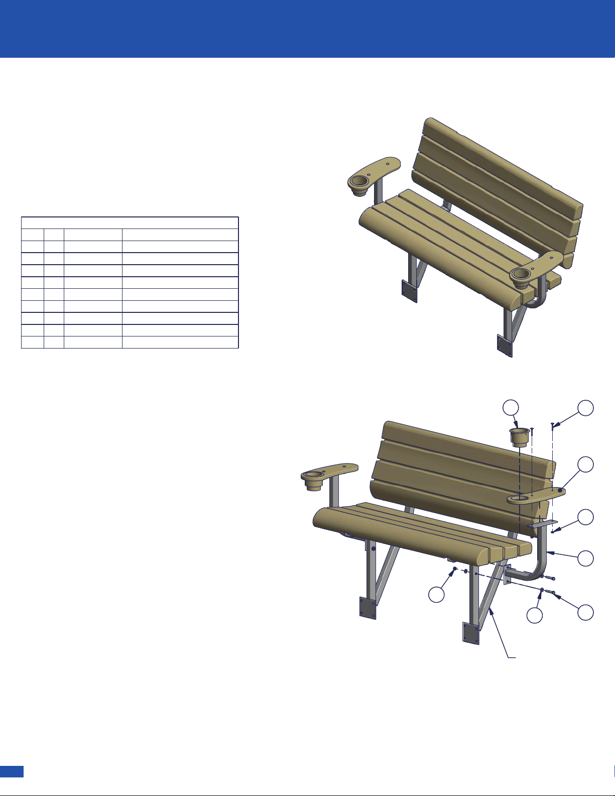
Lakeview
Dock Bench
7
6
1
5
2
4
3
Step 1.
Attach armrest bent arms to dock
bench frame as shown using 3/8" x 2" Hex
Bolts, 3/8" Flat Washers and 3/8" Nyloc Nuts.
Step 2.
Attach armrest tan poly to armrest
bent arm using 1/4" x 1-1/2" Carriage Bolts
and 1/4" Hex Nuts.
Note: Make sure to position armrest tan poly
correctly, as shown.
Step 3.
Insert cupholder into hole in armrest
tan poly.
8
LakeView Bench
Armrest Tan (Pair)
Instructions
Part #: 1007898
Parts List
DESCRIPTION
PART NUMBER
QTY
ITEM
Chair Pocket
101567521
Pedestal Post101568122
Swivel Chair Base 0 Deg - Sea Sense
101680823
Hex Nut 3/8
100180344
T Handle
1000876
75
Hex Nut 1/4
100179786
Flat Washer 1/4
100257416
7
Hex Bolt 1/4 x 1.0
100239888
Washer Lock 5/16 SS
100257289
3
2
1
4
5
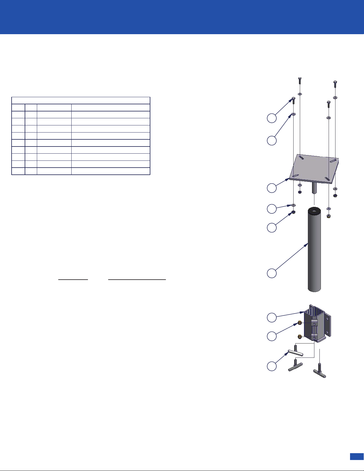
Step 1.
Attach one Chair Base to one Chair Sling Base (sold
separately) with four 1/4 x 1 Hex Bolts, eight 1/4 Flat Washers, four 1/4
Lock Washers, and four 1/4 Hex Nuts - as shown.
Step 2.
Attach the Chair Pocket to your dock brand's Accessory
Adaptor Brackets (Not Included in this kit).
Furniture Hardware Box
Instructions
Part #: 1015721
8
7
6
9
Note: Part #: 1015685 - Set of 2 Chairs, one table, an umbrella, and hardware box.
Connect Furniture Hardware Pocket to accessory bracket (Sold Separately)
according to accessory bracket instructions.
Note: On ShoreMaster Infinity Dock Accessory Connectors Two T-Handles are
required to clamp each Chair or Table to the dock frame.
Dock Type Bracket Part Number
RS4 Dock 1006706
RS7 Dock 1006708
RS9 Dock 1006730
Poly Dock 1006608
Note: Furniture Hardware Pocket will be attached to one of four different type of
Accessory Dock Connectors in order to be attached to your dock. Below is a list
of the four different types of docks and the required bracket.
Step 3.
Insert one Pedestal Post into the Chair Pocket and secure with
two 3/8 Nuts and two T-Handles - as shown.
Step 4.
Insert the Chair Base into the Pedestal Post.
CAUTION: Before use, make sure all connections are properly
tightened. Periodically check all connections.
SHOREMASTER.COM | 15
ACCESSORY INSTALLATION
ACCESSORY INSTALLATION
Parts List
DESCRIPTION
PART NUMBER
QTY
ITEM
Armrest Bent Arm
100789721
Armrest Tan Poly100322422
CUPHOLDER
100176723
Bolt Bag Armrest Lakeview Bench10078931
--
Bolt Carriage 1/4-20 x 1.5 SS 304
1001952
44
Nut Hex 1/4-20 Brass
10017974
5
Washer Flat 3/8 SS
100259986
Bolt Hex 3/8-16 x 2.0 SS 304
10024244
7
Nut Nyloc 3/8-16 Brass
1001805
4
8
Lakeview
Dock Bench
7
6
1
5
2
4
3
Step 1.
Attach armrest bent arms to dock
bench frame as shown using 3/8" x 2" Hex
Bolts, 3/8" Flat Washers and 3/8" Nyloc Nuts.
Step 2.
Attach armrest tan poly to armrest
bent arm using 1/4" x 1-1/2" Carriage Bolts
and 1/4" Hex Nuts.
Note: Make sure to position armrest tan poly
correctly, as shown.
Step 3.
Insert cupholder into hole in armrest
tan poly.
8
LakeView Bench
Armrest Tan (Pair)
Instructions
Part #: 1007898
Parts List
DESCRIPTION
PART NUMBER
QTY
ITEM
Chair Pocket
101567521
Pedestal Post101568122
Swivel Chair Base 0 Deg - Sea Sense
101680823
Hex Nut 3/8
100180344
T Handle
1000876
75
Hex Nut 1/4
100179786
Flat Washer 1/4
100257416
7
Hex Bolt 1/4 x 1.0
100239888
Washer Lock 5/16 SS
100257289
3
2
1
4
5
Step 1.
Attach one Chair Base to one Chair Sling Base (sold
separately) with four 1/4 x 1 Hex Bolts, eight 1/4 Flat Washers, four 1/4
Lock Washers, and four 1/4 Hex Nuts - as shown.
Step 2.
Attach the Chair Pocket to your dock brand's Accessory
Adaptor Brackets (Not Included in this kit).
Furniture Hardware Box
Instructions
Part #: 1015721
8
7
6
9
Note: Part #: 1015685 - Set of 2 Chairs, one table, an umbrella, and hardware box.
Connect Furniture Hardware Pocket to accessory bracket (Sold Separately)
according to accessory bracket instructions.
Note: On ShoreMaster Infinity Dock Accessory Connectors Two T-Handles are
required to clamp each Chair or Table to the dock frame.
Dock Type Bracket Part Number
RS4 Dock 1006706
RS7 Dock 1006708
RS9 Dock 1006730
Poly Dock 1006608
Note: Furniture Hardware Pocket will be attached to one of four different type of
Accessory Dock Connectors in order to be attached to your dock. Below is a list
of the four different types of docks and the required bracket.
Step 3.
Insert one Pedestal Post into the Chair Pocket and secure with
two 3/8 Nuts and two T-Handles - as shown.
Step 4.
Insert the Chair Base into the Pedestal Post.
CAUTION: Before use, make sure all connections are properly
tightened. Periodically check all connections.
16 | SHOREMASTER.COM
ACCESSORY INSTALLATION
Parts List
DESCRIPTION
PART NUMBER
QTY
ITEM
Wdmt QC Umbrella Holder - 1.75" ID
102433811
Bolt Bag - QC Umbrella Holder
10249191
--
Screw 3/8 X 1 1/2 Thumb SS
100242122
Nut Square 3/8-16 SS
100259823
Bolt Carriage 3/8-16 x 1.0 SS 304
100195644
Nut Flange 3/8-16 Brass
10018024
5
2
3
5
4
1
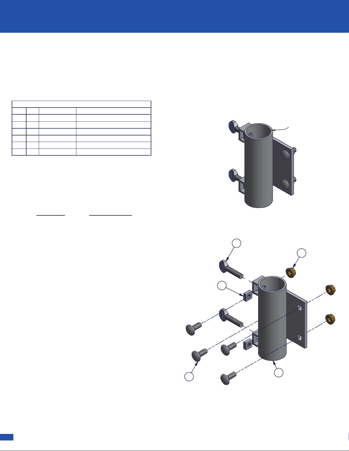
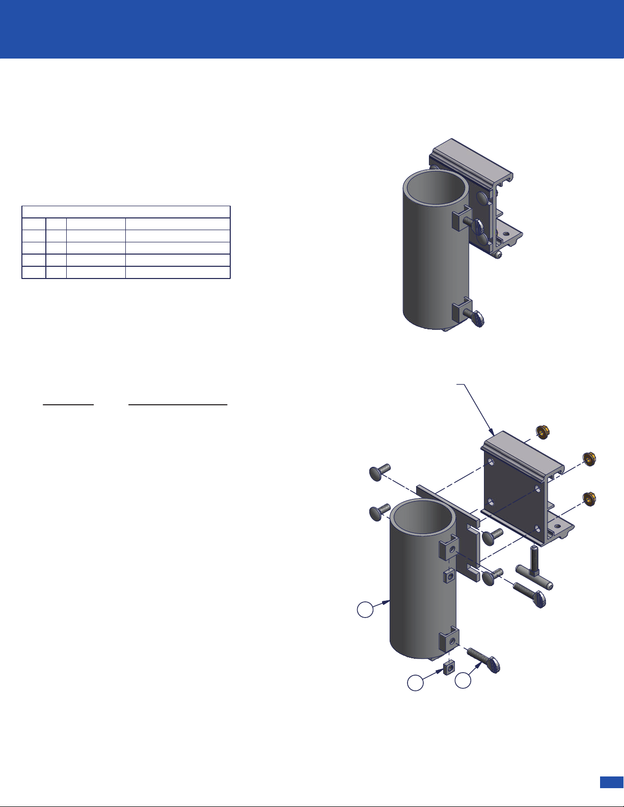
QC Umbrella Holder
Instructions
Part #: 1024339
1
.
7
5
0
Note: QC Umbrella Holder will be attached to one of
four different types of Accessory Dock Connectors in
order to be attached to your dock. Below is a list of the
four different types of docks and the required bracket.
Dock Type Bracket Number
RS4 Dock 1006706
RS7 Dock 1006708
RS9 Dock 1006730
Poly Dock 1006608
Connect QC Umbrella Holder to accessory bracket
(Sold Separately) according to accessory bracket
instructions.
Step 1.
After attaching QC Umbrella Holder to
Accessory Bracket, insert the 3/8 Square Nuts into
nut clips on 1-3/4 ID Umbrella Holder pipe.
Step 2.
Screw the 3/8 Thumb Screws a few turns
into 3/8 Square Nuts, just enough to hold in place.
Step 3
. Insert Umbrella pole into Umbrella Holder to
desired height and tighten 3/8 Thumb Screws.
Parts List
DESCRIPTION
PART NUMBER
QTY
ITEM
QC Flag Pole Holder
100380711
Bolt Bag QC Flag Pole Holder
10044471
-
Screw 3/8 X 1 1/2 Thumb SS
100242122
Nut Square 3/8-16 SS
100259823
2
3
1
Note: QC Flag pole holder will be attached to
one of four different types of Accessory Dock
Connectors in order to be attached to your
dock. Below is a list of the four different types
of docks and the required bracket.
Dock Type Bracket Part Number
RS4 Dock 1006706
RS7 Dock 1006708
RS9 Dock 1006730
Poly Dock 1006608
Connect QC flag pole holder to accessory
bracket (Sold Separately) according to
accessory bracket instructions.
RS4 QC Accessory
Bracket and Hardware
shown (Sold Separately)
QC Flagpole Holder
Instructions
Part #: 1006666
Step 1
. After attaching QC Flagpole Holder to
Accessory Bracket, insert the 3/8 Square Nuts
into nut clips on Flagpole Holder pipe.
Step 2.
Screw the 3/8 Thumb Screws a few turns
into 3/8 Square Nuts, just enough to hold in place.
Step 3
. Insert Flagpole into QC Flagpole Holder
and tighten 3/8 Thumb Screws.
SHOREMASTER.COM | 17
ACCESSORY INSTALLATION
ACCESSORY INSTALLATION
Parts List
DESCRIPTION
PART NUMBER
QTY
ITEM
Wdmt QC Umbrella Holder - 1.75" ID
102433811
Bolt Bag - QC Umbrella Holder
10249191
--
Screw 3/8 X 1 1/2 Thumb SS
100242122
Nut Square 3/8-16 SS
100259823
Bolt Carriage 3/8-16 x 1.0 SS 304
100195644
Nut Flange 3/8-16 Brass
10018024
5
2
3
5
4
1
QC Umbrella Holder
Instructions
Part #: 1024339
1
.
7
5
0
Note: QC Umbrella Holder will be attached to one of
four different types of Accessory Dock Connectors in
order to be attached to your dock. Below is a list of the
four different types of docks and the required bracket.
Dock Type Bracket Number
RS4 Dock 1006706
RS7 Dock 1006708
RS9 Dock 1006730
Poly Dock 1006608
Connect QC Umbrella Holder to accessory bracket
(Sold Separately) according to accessory bracket
instructions.
Step 1.
After attaching QC Umbrella Holder to
Accessory Bracket, insert the 3/8 Square Nuts into
nut clips on 1-3/4 ID Umbrella Holder pipe.
Step 2.
Screw the 3/8 Thumb Screws a few turns
into 3/8 Square Nuts, just enough to hold in place.
Step 3
. Insert Umbrella pole into Umbrella Holder to
desired height and tighten 3/8 Thumb Screws.
Parts List
DESCRIPTION
PART NUMBER
QTY
ITEM
QC Flag Pole Holder
100380711
Bolt Bag QC Flag Pole Holder
10044471
-
Screw 3/8 X 1 1/2 Thumb SS
100242122
Nut Square 3/8-16 SS
100259823
2
3
1
Note: QC Flag pole holder will be attached to
one of four different types of Accessory Dock
Connectors in order to be attached to your
dock. Below is a list of the four different types
of docks and the required bracket.
Dock Type Bracket Part Number
RS4 Dock 1006706
RS7 Dock 1006708
RS9 Dock 1006730
Poly Dock 1006608
Connect QC flag pole holder to accessory
bracket (Sold Separately) according to
accessory bracket instructions.
RS4 QC Accessory
Bracket and Hardware
shown (Sold Separately)
QC Flagpole Holder
Instructions
Part #: 1006666
Step 1
. After attaching QC Flagpole Holder to
Accessory Bracket, insert the 3/8 Square Nuts
into nut clips on Flagpole Holder pipe.
Step 2.
Screw the 3/8 Thumb Screws a few turns
into 3/8 Square Nuts, just enough to hold in place.
Step 3
. Insert Flagpole into QC Flagpole Holder
and tighten 3/8 Thumb Screws.
18 | SHOREMASTER.COM
ACCESSORY INSTALLATION
Parts List
DESCRIPTION
PART NUMBER
QTY
ITEM
Wdmt Fishing Rod Holder102511011
RS4 Quick-Connect Accessory Bracket (sold separate)
10067061
--
Accessory Connector Clamp 4.5 - Rs4
100282312
Bolt Bag - QC Accessory Connector Bracket
10044321
--
T Handle 3/8-16 x 1.5 x 2.5 w/ Cup Point
100087613
Bolt Carriage 3/8-16 x 1.0 SS 304
100195644
Nut Flange 3/8-16 Brass
10018024
5
1
4
3
2
5
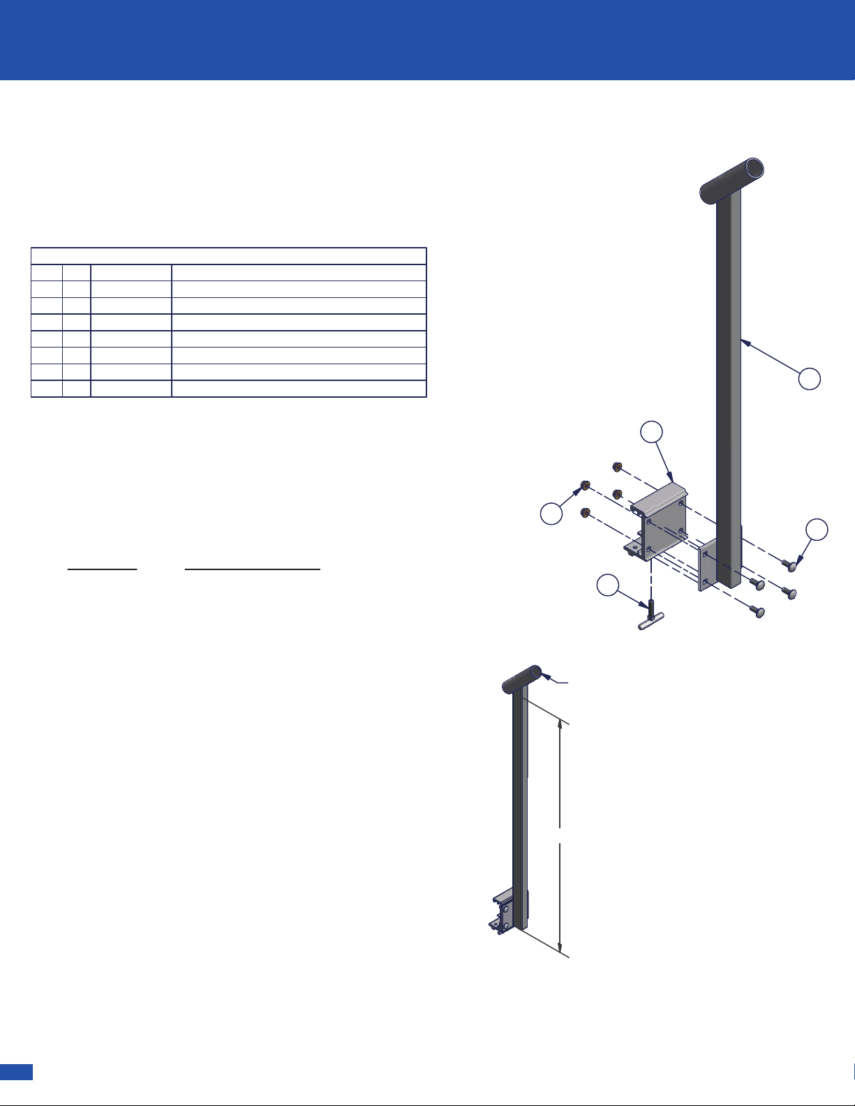
Step 1.
Attach fishing rod holder to accessory
bracket using 3/8 x 1 Carriage Bolts and 3/8 Flange
Nuts.
Step 2.
Slide handle of fishing rod into tube.
Note: Not all fishing rods will work. Rod holder is
about 32" from deck surface and will accept up to a
1-3/8" diameter rod handle.
36
.
1
2
5
Ø 1-3/8" I.D.
QC Fishing Rod Holder
Instructions
Part #: 1016581
Dock Type Bracket Part Number
RS4 Dock 1006706
RS7 Dock 1006708
RS9 Dock 1006730
Poly Dock 1006608
Note: QC Fishing Rod holder will be attached to
one of four different type of Accessory Dock
Connectors in order to be attached to your dock.
Below is a list of the four different types of docks
and the required bracket.
Connect QC Fishing Rod holder to accessory
bracket (Sold Separately) according to accessory
bracket instructions.
DETAIL B
DETAIL A
B
A
Parts List
DESCRIPTION
PART NUMBER
QTY
ITEM
Cleat Attachment Bracket
100275921
Cleat
100108912
Screw 5/16 x 2.25
100052623
L
3
2
1
1
Step 1.
Insert two Cleat Attachment
Brackets 4.0 into the Attachment Groove on
the top of the dock rail and slide together - as
shown in Detail "A".
Step 2.
Set the Plastic Cleat 8.0 on the two
Cleat Attachement Brackets 4.0 and secure
with two 5/16 x 2 1/4 Screws using a Torx bit
driver - as shown in Detail "B".
Attachment Groove
QC Cleat Kit
Instructions
Part #: 1006655

SHOREMASTER.COM | 19
ACCESSORY INSTALLATION
ACCESSORY INSTALLATION
Parts List
DESCRIPTION
PART NUMBER
QTY
ITEM
Wdmt Fishing Rod Holder102511011
RS4 Quick-Connect Accessory Bracket (sold separate)
10067061
--
Accessory Connector Clamp 4.5 - Rs4
100282312
Bolt Bag - QC Accessory Connector Bracket
10044321
--
T Handle 3/8-16 x 1.5 x 2.5 w/ Cup Point
100087613
Bolt Carriage 3/8-16 x 1.0 SS 304
100195644
Nut Flange 3/8-16 Brass
10018024
5
1
4
3
2
5
Step 1.
Attach fishing rod holder to accessory
bracket using 3/8 x 1 Carriage Bolts and 3/8 Flange
Nuts.
Step 2.
Slide handle of fishing rod into tube.
Note: Not all fishing rods will work. Rod holder is
about 32" from deck surface and will accept up to a
1-3/8" diameter rod handle.
36
.
1
2
5
Ø 1-3/8" I.D.
QC Fishing Rod Holder
Instructions
Part #: 1016581
Dock Type Bracket Part Number
RS4 Dock 1006706
RS7 Dock 1006708
RS9 Dock 1006730
Poly Dock 1006608
Note: QC Fishing Rod holder will be attached to
one of four different type of Accessory Dock
Connectors in order to be attached to your dock.
Below is a list of the four different types of docks
and the required bracket.
Connect QC Fishing Rod holder to accessory
bracket (Sold Separately) according to accessory
bracket instructions.
DETAIL B
DETAIL A
B
A
Parts List
DESCRIPTION
PART NUMBER
QTY
ITEM
Cleat Attachment Bracket
100275921
Cleat
100108912
Screw 5/16 x 2.25
100052623
L
3
2
1
1
Step 1.
Insert two Cleat Attachment
Brackets 4.0 into the Attachment Groove on
the top of the dock rail and slide together - as
shown in Detail "A".
Step 2.
Set the Plastic Cleat 8.0 on the two
Cleat Attachement Brackets 4.0 and secure
with two 5/16 x 2 1/4 Screws using a Torx bit
driver - as shown in Detail "B".
Attachment Groove
QC Cleat Kit
Instructions
Part #: 1006655

20 | SHOREMASTER.COM
ACCESSORY INSTALLATION
Parts List
DESCRIPTION
PART NUMBER
QTY
ITEM
Poly Vertical Roto Bumper Black
100426111
Poly Vertical Roto Bumper Blue10042551
Poly Vertical Roto Bumper Tan
10042561
Poly Vertical Roto Bumper White10042541
QC Vertical Bumper Bracket w/Bolt Bag
10042651
-
QC Vertical Bumper Bracket Weldment
100379012
Slider Leg 37.75" Vert. Roto Bumper
100311913
Gray Cap 2 X 2 X 2
100086824
Bolt Bag Qc Vertical Bumper Bracket
10044331
-
Washer Flat 3/8 SS
10025993
5
Nut Flange 3/8-16 Brass
1001802
4
6
Nut Nyloc 3/8-16 Brass
10018053
7
Bolt Carriage 3/8-16 x 4.0 SS 304
100196328
Bolt Carriage 3/8-16 x 1.0 SS 304
1001956
5
9
Note: QC Vertical Dock Bumper will be attached to one of four
different type of Accessory Dock Connectors in order to be
attached to your dock. Below is a list of the four different types of
docks and the required bracket.
Dock Type Bracket Part Number
RS4 Dock 1006706
RS7 Dock 1006708
RS9 Dock 1006730
Poly Dock 1006608
Note: In order to attach vertical dock bumper to a dock not listed
above use two 3/8 x 3-1/2 Carriage Bolts and two 3/8 Flange
Nuts (provided).
4
6
8
1
5
7
9
3
2
QC Vertical Roto Bumper
Instructions
Part #: 1006690 (Black)
Part #: 1006691 (Blue)
Part #: 1006692 (Tan)
Part #: 1006693 (White)
Step 1
. Attach QC accessory bracket to QC
vertical bumper bracket weldment using
hardware from QC accessory bracket 3/8 x 1
Carriage Bolts and 3/8 Flange Nuts.
Step 2.
Attach QC vertical bumper bracket to
slider leg (at desired height) using 3/8 x 1
Carriage Bolts and 3/8 Flange Nuts.
Step 3.
Attach Roto Bumper to slider leg using
3/8 x 1 Carriage Bolts and 3/8 Flange Nuts (set
to desired height before tightening nuts).
Step 4.
Slide the caps onto top and bottom of
slider leg.
Parts List
DESCRIPTION
PART NUMBER
QTY
ITEM
QC Vertical Bumper Bracket Weldment
100379021
Slider Leg 37.75" Vert. Roto Bumper
100311922
Weldment QC - Canoe / Kayak Rack Arm
101676623
Bolt Bag QC - Canoe / Kayak Rack
10167651
--
Cap Blue #14 - 2.0 x 2.0 x 2.0
100181564
Bolt Carriage 3/8-16 x 1.0 SS 304
10019568
5
Nut Flange 3/8-16 Brass
100180286
RS4 QC Accessory Bracket (sold separate)
10067062
7
RS7 QC Accessory Bracket (sold separate)
10067082
7
TS9 QC Accessory Bracket (sold separate)
10067302
7
Poly Dock 6" Accessory Bracket (sold separate)
10066082
7
4
3
6
2
5
7
1
3
2
.
0
0
37
.
7
5
Note: Arm is 32" long and has
about 36" of vertical adjustment.
Added for
double option.
QC Canoe / Kayak Rack (Pair)
Instructions
Part #: 1016764
Step 1. Attach QC accessory bracket (sold
separately) to QC vertical bumper bracket weldment
using hardware from QC accessory bracket 3/8 x 1
Carriage Bolts and 3/8 Flange Nuts.
Step 2.
Attach QC vertical bumper bracket to slider
leg (at desired height) using 3/8 x 1 Carriage Bolts and
3/8 Flange Nuts.
Step 3.
Attach QC canoe / kayak rack arm to slider
leg using 3/8 x 1 Carriage Bolts and 3/8 Flange Nuts
(set to desired height before tightening nuts).
Step 4.
Slide the caps onto top and bottom of slider
leg and on end of QC canoe / kayak rack arm.
Step 5.
Attach QC canoe / kayak rack to dock using
accessory bracket, space racks apart so the racks are
towards the end of the canoe or kayak.
Note: Use a bungee cord to secure canoe or kayak to
rack. Use the holes in the bottom of QC canoe / kayak
rack arm to secure the bungee cord.
Other manuals for Infinity RS4
1
Other Shoremaster Marine Equipment manuals


