Fulleon ROLP User manual

Product Manual for ROLP Sounder M96-024 Issue 4
Page 1 of 14
Contents
Title
Page
INTRODUCTION
2
GENERAL FUNCTIONAL DESCRIPTION 2
TONES TABLE 3
SPL DIRECTIONAL OUTPUT VARIATION 4,5
Start Up Current at Minimum, Nominal & Maximum Supply Voltage
6,7
SPL-V-Input Voltage
7
Input Current -V- Input Voltage Data
8
Installation Guidance & Advise
8
Power Supplies & Control Panels 9
Wiring 9
Detailed wiring diagrams 10, 11
Typical Loop Calculations & Recommendations
12
Maintenance Advice
13
Product Dimensions
13
Annex A: Document Change Summary 14
www.acornfiresecurity.com

Product Manual for ROLP Sounder M96-024 Issue 4
Page 2 of 14
Introduction
The ROLP sounder is an affordable wall mounting sounder which is suitable for audible
signalling within open areas or corridors and passages. The sounder is designed for use within
fire alarm systems, intruder alarm systems and industrial signalling systems. It is able to
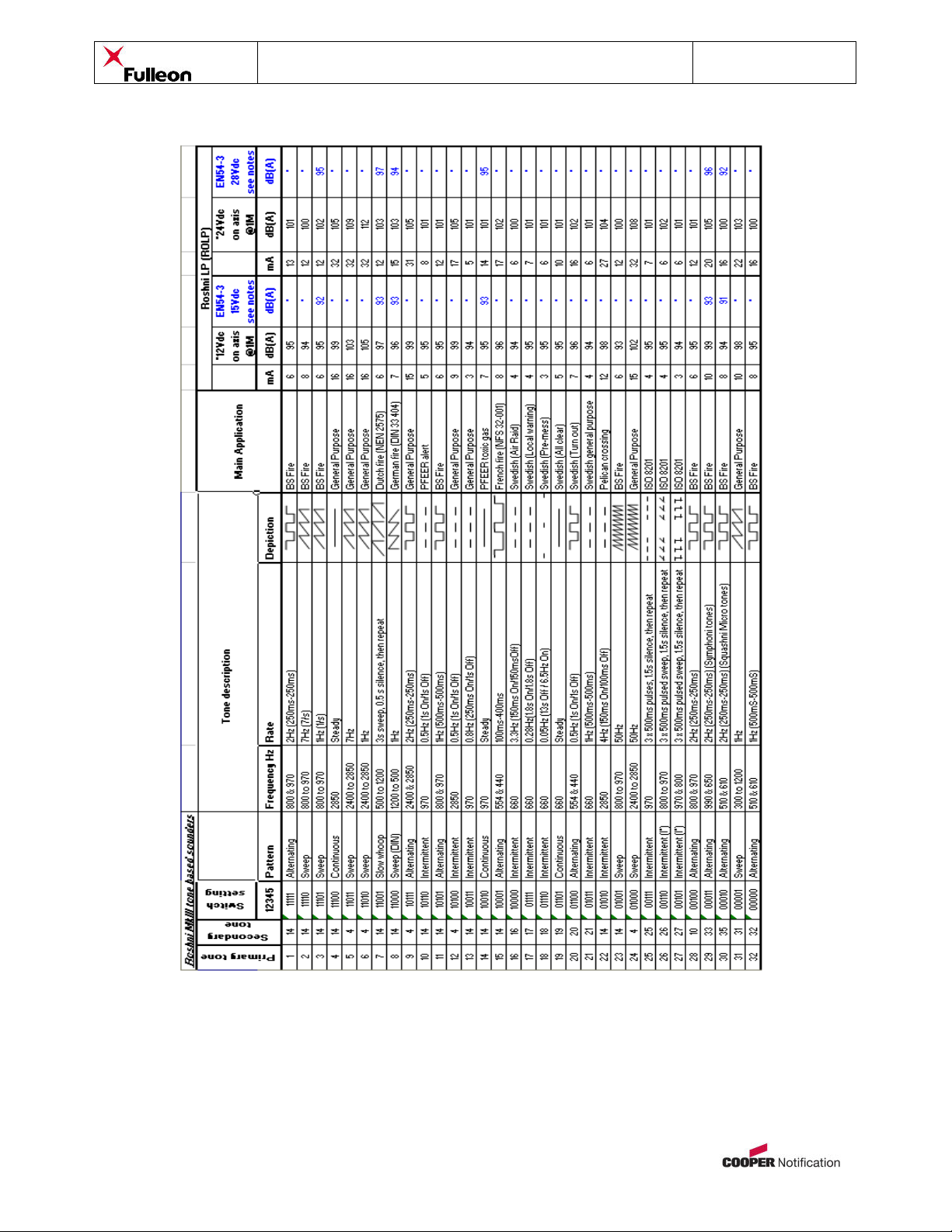
produce 32 tones via the coding switch on the rear of the unit (see installation sheet/tones table
for more detail). A second tone can be activated remotely by using the third terminal. A volume
control adjustment is also provided.
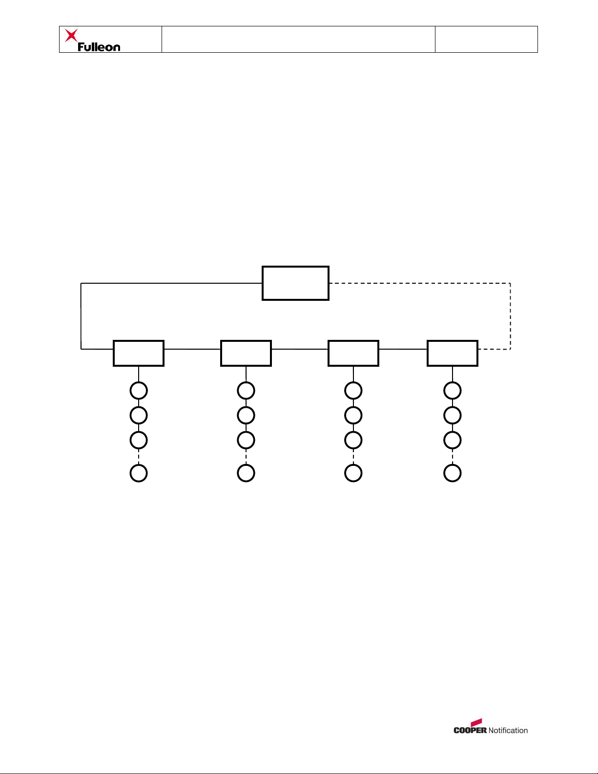
Connection is via a screw terminal connector block for ease of termination of cables. Each
connection has a terminal for looping in and out. The sounder is fixed to a location using a
bespoke shallow clip on lockable base.
General Functional Description
The device is normally in an off state, with no voltage applied to the power terminals. In this
state, the unit has no power and so does not produce any sound.
When the unit is required to produce sound, a voltage between 9 and 15 D.C. or 18-28V DC is
applied to the appropriate power terminals. This provides power to the circuit via a polarity
protection diode, & an RC network which provides supply smoothing and noise immunity
protection. Further protection is also provided against voltage spikes on the supply. At the heart
of the sounder is a microprocessor which derives its power from a linear voltage regulator
circuit. Clock timing and sounder synchronisation is provided via the oscillator clock drive crystal
& associated capacitor network.
The tone generated by the microprocessor depends on the tone switch settings. After power up
and initialisation, the firmware code starts executing the relevant pulse output from the
microprocessor. This drives a transistor circuit which in turn drives a push/pull amplifier
arrangement which drives the loudspeaker circuit.
Some adjustment of the output sound level can be achieved using the volume control
adjustment (if provided), which reduces the current drive to the transducer.
If the user wishes to select a second tone remotely, the additional connection on the terminal
block is taken to ground (i.e. -ve supply to “2nd TONE -” terminal). This sets the microprocessor
firmware to generate a different tone.
Notes:
•See Installation sheet for details on technical specifications, connection instructions &
mounting arrangements.
www.acornfiresecurity.com

Product Manual for ROLP Sounder M96-024 Issue 4
Page 3 of 14
Tones Table
Note (a): Tones approved under the Construction Products Directive for Fire Alarm Applications, are shown in the column marked
EN54-3.
Note (b): EN54-3 measurements shown reflect minimum expected SPL readings at Maximum Volume at the Loudest Point around the
EN54-3 defined sounder axis.
Note (c): All other tone measurements reflect mean manufacturers data based on 'on axis' measurements, and are not verified by a
Notified body.
Note (d): Detailed EN54-3 polar SPL measurements are available in this Product Manual.
Note (e): All measurements taken at 20oC operating temperature.
Note (f): For SPL figures at 12V DC, take 6dB of the readings for 24V DC.
www.acornfiresecurity.com

Product Manual for ROLP Sounder M96-024 Issue 4
Page 4 of 14
Directional Output Variation
The tables below show the sounders SPL in accordance with EN54-3.
Operational Performance – Tone 3.
Operational performance
Specimen 1
Maximum Volume dB(A)
Angle
Horizontal Plane
Vertical Plane
Min dB
9.0V
Max dB
15.0V
Differenc
e dB
Min dB
9.0V
Max dB
15.0V
Differenc
e dB
15
°
80 84 <6 79 84 <6
45
°
79 83 <6 80 85 <6
75
°
89 93 <6 89 94 <6
105
°
88 93 <6 88 93 <6
145
°
78 82 <6 77 82 <6
165
°
78 82 <6 80 85 <6
Operational performance
Specimen
1
Maximum Volume dB(A)
Angle
Horizontal Plane Vertical Plane
Min
9.0V
Max
15.0V
Differenc
e
Min
9.0V
Max
15.0V
Differenc
e
15
°
80 85 <6 81 86 <6
45
°
78 84 <6 81 86 <6
75
°
89 94 <6 90 95 <6
105
°
89 94 <6 89 94 <6
145
°
79 84 <6 78 83 <6
165
°
80 85 <6 81 86 <6
www.acornfiresecurity.com

Product Manual for ROLP Sounder M96-024 Issue 4
Page 5 of 14
Operational performance
Specimen
1
Maximum Volume dB(A)
Angle
Horizontal Plane
Vertical Plane
Min
9.0V
Max
15.0V
Differenc
e
Min
9.0V
Max
15.0V
Differenc
e
15
°
80 85 <6 81 86 <6
45
°
79 84 <6 80 85 <6
75
°
89 94 <6 89 94 <6
105
°
89 94 <6 88 93 <6
145
°
79 84 <6 77 82 <6
165
°
80 85 <6 81 86 <6
Operational performance
Specimen 1
Maximum Volume dB(A)
Angle
Horizontal Plane Vertical Plane
Min
9.0V
Max
15.0V
Differenc
e
Min
9.0V
Max
15.0V
Differenc
e
15
°
79 84 <6 78 83 <6
45
°
75 80 <6 79 84 <6
75
°
88 93 <6 89 94 <6
105
°
88 93 <6 88 93 <6
145
°
76 81 <6 76 81 <6
165
°
77 82 <6 80 85 <6
www.acornfiresecurity.com

Product Manual for ROLP Sounder M96-024 Issue 4
Page 6 of 14
ROLP: Start Up Current at 9 volts
ROLP: Start Up Current at 18 volts
Tested using:
TTi PSU PPL330QMD Serial No 128020
PICOSCOPE ADC216 Serial No DSR48/057
Tested using:
TTi PSU PPL330QMD Serial No 128020
PICOSCOPE ADC216 Serial No DSR48/057
www.acornfiresecurity.com

Product Manual for ROLP Sounder M96-024 Issue 4
Page 7 of 14
ROLP: Start Up Current at 28 volts
ROLP: SPL v Input Voltage 9 – 28VDC
ROLP: SPL v Input Voltage 9-28VDC
88.0
90.0
92.0
94.0
96.0
98.0
100.0
102.0
104.0
106.0
108.0
9 12 15 18 24 28
Voltage (V)
SPL (dB)
SPL @1M
ROLP: SPL v Input Voltage 9 – 28VDC
Voltage 9 12 15 18 24 28
SPL @1M 95.0 97.9 100.1 101.7 104.2 105.5
SPL @ 2M 92.0 94.9 97.1 98.7 101.2 102.5
ROLP: Input Current v Input Voltage 9 – 30VDC
Tested using:
TTi PSU PPL330QMD Serial No 128020
PICOSCOPE ADC216 Serial No DSR48/057
www.acornfiresecurity.com

Product Manual for ROLP Sounder M96-024 Issue 4
Page 8 of 14
ROLP: Input Current v Input Voltage 9-28VDC
0
5
10
15
20
25
9 12 15 18 24 28
Voltage (V)
Current (mA)
Current (mA)
ROLP: Input Current v Input Voltage 9 – 28VDC
Voltage 9 12 15 18 24 28
Current (mA) 6.72 9.14 11.73 14.38 19.51 22.33
Installation Guidance & Advise
General Safety Advice
•Do not work on live circuits
•Follow local wiring regulations where relevant
•Ensure that the base is secured to the mounting surface using the most
appropriate fixings. Plasterboard walls will require special wall plugs.
Maintaining IP (Ingress Protection) ratings – Good Practice
•Use suitable cable glands to maintain the designed IP rating. The stated product
rating will ONLY be achieved if the product is installed correctly. A selection of
suitable glands is available from all good electrical wholesalers. Always follow the
cable gland instructions.
•Product orientation is important. If it is desired to achieve a high weatherproof
rating, all cables should be brought in and out from the underside of the device.
Avoid cable entry from the top side, as water could drain in over time.
•Ensuring that all base and mounting screws are secure.
www.acornfiresecurity.com

Product Manual for ROLP Sounder M96-024 Issue 4
Page 9 of 14
Power Supplies / Control Panels
•Use a power supply or control panel capable of providing a steady state current of
at least 1.2 x the rated operating current of each device.
•Use a power supply or control panel capable of providing a surge current of at
least 1.5 x the surge current of each device for at least 10mS.
•A suitable slow-blow fuse must be fitted to the output stage of all power supplies,
to help prevent fuse blowing during power up.
•Where a large number of units are to be wired, it is recommended to use multiple
power supplies on separate spurs or loops to avoid the huge voltage drops that
would otherwise be encountered. See diagram below: -
Control Panel
Local
PSU
Local
PSU
Local
PSU
Local
PSU
Sounder
Sounder
Sounder
Sounder
Control
Circuit
Power Spur
www.acornfiresecurity.com

Product Manual for ROLP Sounder M96-024 Issue 4
Page 10 of 14
Wiring
It is essential to know the series resistance of the cable before making a choice
here. It is recommended that the thickest wire possible is used. This ensures that the
series resistance is minimised and thus the length of the wiring that can be used is
maximised. All the measurements and calculations shown on the following pages are for
a maximum solid core wire cross sectional area (CSA) of 2.5mm2. If using a different
cable type, CSA or a material other than copper is used the value of the series resistance
of the cable (Rs) will need to be adjusted in the formula below.
Please note that that all calculations here are for spurs only. It is risky to do
calculations on loops, since if one side of a loop were to fail, the maximum equivalent
series resistance could double. This may result in possible system start up problems or
poor performance issue due to excessive voltage drops.
Typical Wiring Configuration
EOL
device
Control Panel
/ PSU
+
-
+
-
+
-
+
-
+
-
+
-
+
-
+
-
www.acornfiresecurity.com

Product Manual for ROLP Sounder M96-024 Issue 4
Page 11 of 14
ROLP Wiring Instruction details
+Vdc in
-V in tone stage 1
-V in tone stage 2
+V out to next device
-V out for tone stage 1
-V out for tone stage 2
Volume Control turn
clockwise to increase volume
Tones control switch
www.acornfiresecurity.com

Product Manual for ROLP Sounder M96-024 Issue 4
Page 12 of 14
Typical Calculations (ROLP for example purposes ONLY)
No. of
products
(N)
Typical max current
consumption of
product
(Is) - Amps
Typical power
supply steady
state capability
(Ip) - Amps
Max cable resistance for
10% voltage drop @
10VDC
(Rc) - ohms
Max cable length for
10% voltage drop @
11.2VDC
(L) - Meters
1 0.033 0.04
(
a
)
25
(b)
7142
2 0.066 0.08 12.5 3571
3
0.
099
0
.
12
8.3
2371
4
0.132
0.1
6
6.3
1800
5
0.165
0
.
20
5
1428
Recommendations & Assumptions:
oCopper wire with core cross sectional area (CSA) of 2.5mm2is assumed to be used
oRS(Maximum series resistance of copper wire) = 0.7ohm per 100meters (typical)
oPower supplies must be capable of delivering surge currents of 1.5x surge current of
each device for at least 10mS
oAll sounders are assumed to be wired to the end of a spur (i.e. worst case scenario)
oWhere the length of cable or number of sounders used becomes an issue, it is
recommended to group units together and use a separate power supply & wiring spur
for each group
Formulae:
oCable Resistance: Rc= Vdrop / Is(where Vdrop = 10 x 10%)
= 1V / Is
= 1V / 0.04 = 25 ohm (a)
oCable Length: L = Rc/ [Rs/(100 x2)] (assumes feed / return (+/-) wires are same length & diameter)
= Rc/ 0.0035 ohm
= 25 ohm / 0.0035 ohm = 7142 meters (b)
* Note: All calculations and advice given is for guidance ONLY. No liability is assumed by the manufacture for the use of these
calculations, or for any errors or omissions. The installer is responsible for ensuring that the product is installed correctly and safely
using all relevant & current wiring regulations & practices.
www.acornfiresecurity.com

Product Manual for ROLP Sounder M96-024 Issue 4
Page 13 of 14
Maintenance Advice
•The product is of a low maintenance design. However, systems should be tested
on a regular basis after installation. This is vital where products are used in life
safety systems. Please refer to current & relevant maintenance practices.
•If the product is installed in a harsh environment, check seals and housing
condition for any obvious signs of ware and tear or damage on a periodic basis.
•Cleaning of the product housing should be carried out using non-abrasive and
non-corrosive substances. A lightly moistened soft cloth is usually sufficient.
Product Dimensions
www.acornfiresecurity.com

Product Manual for ROLP Sounder M96-024 Issue 4
Page 14 of 14
Annex A: Document Change Summary
Issue
Description Of Change
By whom
Date
A Original Document Not known Date unknown
2 Added ROLP to new format SM 27/11/08
3
Added temporary ‘Requires Update’ comments in who document &
‘By whom’ column on Document change Summary SM 03/12/08
4 Updated document to standard format. PW 05/05/09
www.acornfiresecurity.com
Table of contents
Other Fulleon Marine Equipment manuals