manuals.online logo
Brands
  1. Home
  2. •
  3. Brands
  4. •
  5. Ziton
  6. •
  7. Marine Equipment
  8. •
  9. Ziton ZP755HA-2P Assembly instructions

Ziton ZP755HA-2P Assembly instructions

ZP755HA-2 Addressable Omnidirectional
Sounder Installation Sheet
Description
The ZP755HA-2 is an addressable, omnidirectional horn
sounder, designed for use on Ziton analogue addressable fire
detection and alarm systems.
The device includes a volume control, an address-setting
switch, programmable tone settings, and a pair of jumpers to
select the operating power — from the analogue addressable
loop or an external supply. The sounder plugs into a base that
is purchased separately. See Table 1 for a list of model
numbers.
Table 1: Models
Model number Description
Sounder:
ZP755HA-2R
ZP755HA-2P
Addressable, horn sounder, Red
Addressable, horn sounder, Polar white
Base:
SPB-2R
SPB-2P
Plug in-base, Red
Plug in-base, Polar White
Installation
To install the device follow these general steps.
1. Wire the base.
2. Set the operating power.
3. Set the address.
4. Set the mode of operation.
5. Set the tone.
6. Set the volume.
7. Mount the sounder onto the base.
The details of each step are given below.
Wiring the base
Connect the loop wiring for the plug-in base as shown in
Figure 1. There is no wiring between the sounder and plug-in
base.
Figure 1: Loop wiring for the plug-in base
1. Ext. 24 VDC+ IN/OUT
2. Ext. 24 VDC ground IN/OUT
5. Loop+ IN/OUT
6. Loop − IN/OUT
7. Shield
Setting the operating power
The sounder includes a pair of power selection jumpers, J1
and J2. To select the source of the sounder operating power,
position the jumpers as shown in Figure 2.
Figure 2: Power-selection jumper configuration
1. Loop powered 2. External 24 VDC
Note: When using an external power supply, use only one that
is CE and EN 54-4 compliant to power all the sounders on the
same loop.
6
2
5
1
J1 J1J2 J2
21
www.acornfiresecurity.com
Setting the address
The sounder includes a seven-segment DIP switch (SW1) for
assigning device addresses. Each switch segment represents
the value shown in Figure 3. The address is the sum of all the
switch segments in the ON position. The switch is used to set
the device address in binary code. The switch may be set to
represent any address from 1 to 127.
For example, to select a device address of 007, set SW1-1,
SW1-2, and SW1-3 to the ON position and the remaining
switch segments to the OFF position.
Figure 3: Address switch setting
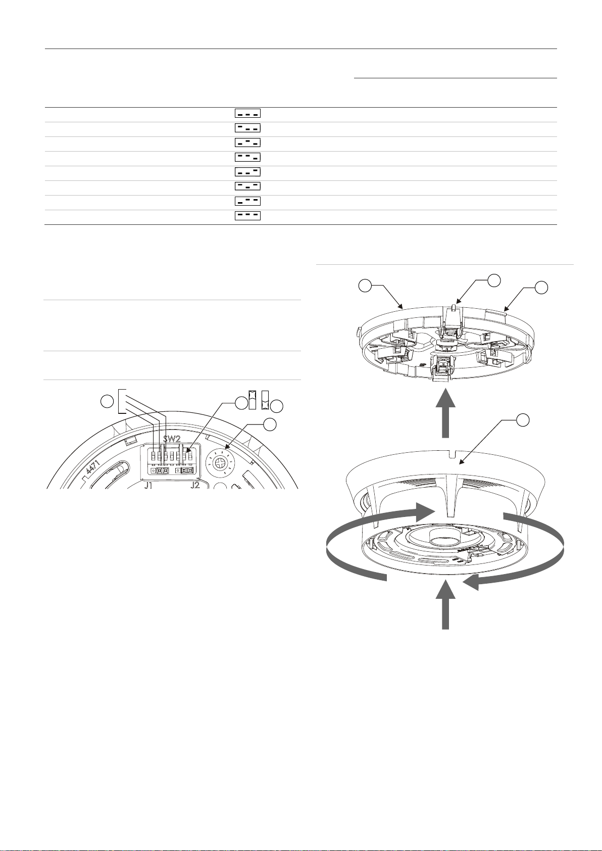
Mode and tone settings
The sounder includes a seven-segment DIP switch (SW2) to
select operating mode, device mode, and tone. See Figure 4.
Figure 4: Mode of operation switch settings
1. Power selection jumpers
2. SW2 configuration switch
3. Tone
4. Device mode
5. Operating mode
Setting the operating mode
The device operates as a dedicated (stand-alone) sounder with
its own unique loop address when SW2-7 is set to ON.
To configure operation as a stand-alone sounder:
1. Set SW2-7 to ON.
2. Navigate to the following menu to tag the sounders as
SAB:
ZP3 Panel Menu/Setup/Sounders/SAB/Add SAB
The Planner can also be used.
3. To map an alert-to-evac function, make the first input type
a fast flash input.
The sounder will sound the alert tone in response to a fast
flash input or an evac tone when the input configured as
steady is triggered, overriding the alert tone.
Setting the device mode
SW2-6 selects whether the loop sounder operates in ZP755
mode or in ZP754 emulation mode as described in Table 2.
Table 2: SW2-6 mode selection switch
Mode SW2-6 Output Signal Requirement
ZP755 OFF User-selectable two-
tone operation and
full monitoring
ZP3 software
v1.18 or later
ZP754
emulation ON Two fixed tones ZP5 panels or
ZP3 panels with
legacy software
Setting the tone
Two different tones can be programmed to operate from the
panel. In ZP755HA mode these tones are selected using SW2-
1, SW2-2, and SW2-3. Refer to Table 3.
Note: In the ZP panel I/O mapping menu, outputs are
programmed as "steady" or "flashing." The link to the table
below is as follows:
• Tone A = Panel setting "fast flash/slow flash.”
• Tone B = Panel setting "steady.”
1
2
34
5
www.acornfiresecurity.com
Table 3: Tone settings
SW2-6 device mode
switch setting Device mode SW2 switch setting
-1 -2 -3 Mapping input type
Fast flash Steady
Tone type
Tone A primary/alert Tone B secondary/evac
OFF ZP755 0 Intermittent Continuous
OFF ZP755 1 Continuous Intermittent
OFF ZP755 2 Continuous Two-tone
OFF ZP755 3 Two-tone Continuous
OFF ZP755 4 Two-tone Intermittent
OFF ZP755 5 Intermittent Two-tone
OFF ZP755 6 Not used
ON ZP754 7 Intermittent Continuous
Setting the volume
Refer to Figure 5. The sounder has a volume control
potentiometer to adjust the volume.
WARNING: To conform to EN 54 Part 3 sound output levels,
the volume control must be set to the full clockwise position. If
the volume is adjusted for any reason, it must be returned to
the full clockwise position.
Figure 5: Volume control
1. Tone select
2. SW2-6 on
3. SW2-6 off
4. Volume control
Mounting the sounder onto the base
Refer to Figure 6. Align the addressable sounder to the plug-in
base. Push up (A) and turn the sounder until it clicks into place
(B). Push the sounder up once more to engage (C).
Reverse the above procedure to remove the sounder from the
base.
Figure 6: Mounting
1. Addressable sounder
2. Release aid (3X)
3. Release/lock catch
4. Plug-in base
Sounders per loop
The sounder can be powered directly from the loop of a ZP5 or
ZP3 panel. Use Table 4, in conjunction with Figure 7, to
determine the quantity of detectors and sounders that can be
connected to a two-core shielded loop.
1
2
3
123
4
4
3
2
1
A
B
C
www.acornfiresecurity.com
Figure 7: Detector/sounders per loop
A. Cable length panel to first sounder
B. Cable length first to last sounder
C. Cable length last sounder to panel
1. Detectors and Sounders
Table 4: Maximum detectors and sounders per loop
A B C Quantity allowed [1]
10 m 980 m 10 m 50 detectors and 50 sounders
63 detectors and 42 sounders
100 m 800 m 100 m 45 detectors and 45 sounders
63 detectors and 40 sounders
200 m 600 m 200 m 40 detectors and 40 sounders
63 detectors and 37 sounders
300 m 400 m 300 m 37 detectors and 37 sounders
63 detectors and 35 sounders
[1] Using a two-core shielded loop of 1000 meters cable size 1.5 mm²
Specifications
Operating voltage
External supply
Loop supply, ZP protocol
18 to 30 VDC
19.5 to 20.5 V pulsed, max. 4 V line
loss
Current (line powered)
Quiescent (RMS)
Alarm (RMS)
Alarm (excluding device
address)
Alarm (at device address)
820 µA
6.4 mA
9.4 mA max.
25 mA max.
Current (externally powered)
Quiescent (RMS)
Alarm (RMS)
Maximum number
470 µA
500 µA
50 per 1 km loop (subject to cable
size and sounder spacing)
Sound output
Tone 1
Tone 2
Tone 3
90 dBA (all around)
Continuous 980 Hz
Intermittent 980 Hz (0.5 sec on/off)
Two-tone warble 980 Hz/670 Hz
Sound distribution Wide
CNPP anechoic sound levels See Figure 8
Monitoring
ZP loop
Sound output level
Open and short circuit fault
Self test facility
Compatibility Ziton analogue addressable
systems
Addressing method 7-segment DIP switch
Mounting Surface, with plug-in base
Wiring Two-core loop
Construction
Material
Weight
Dimensions (Ø × D)
Moulded thermoplastic
275 g
127 × 113 mm
Operating environment
Temperature
Relative humidity
−10 to +60°C
10 to 95%, noncondensing
Storage temperature −20 to +70°C
Figure 8: CNPP anechoic sound levels
A
C
B
1
165
O
105
O
75
O
45
O
15
O
135
O
dBA 70 75 80 857075808590 90
www.acornfiresecurity.com

This manual suits for next models

3

Other Ziton Marine Equipment manuals

Ziton ZP755BV-4 Assembly instructions

Ziton

Ziton ZP755BV-4 Assembly instructions

Ziton ZP755B-2 Assembly instructions

Ziton

Ziton ZP755B-2 Assembly instructions

Ziton ZP755WV-2R Assembly instructions

Ziton

Ziton ZP755WV-2R Assembly instructions

Ziton ZP755HA-2 Assembly instructions

Ziton

Ziton ZP755HA-2 Assembly instructions

Ziton ZP755R-2 Assembly instructions

Ziton

Ziton ZP755R-2 Assembly instructions

Ziton ZP755W-2R Assembly instructions

Ziton

Ziton ZP755W-2R Assembly instructions

Ziton ZP755W-2R Assembly instructions

Ziton

Ziton ZP755W-2R Assembly instructions

Popular Marine Equipment manuals by other brands

Teledyne STREAMPRO Guide

Teledyne

Teledyne STREAMPRO Guide

Elmdene INT400 instruction sheet

Elmdene

Elmdene INT400 instruction sheet

Teleflex Marine BayStar installation manual

Teleflex Marine

Teleflex Marine BayStar installation manual

Mercury NMEA 2000 instructions

Mercury

Mercury NMEA 2000 instructions

GST C-9404(Ex) manual

GST

GST C-9404(Ex) manual

Furuno NAVNET 3D MFDBB Software instructions

Furuno

Furuno NAVNET 3D MFDBB Software instructions

Radian M2 installation guide

Radian

Radian M2 installation guide

Volvo Penta B7 owner's manual

Volvo Penta

Volvo Penta B7 owner's manual

ALBIN PUMP Marine Defroster 9 kW Instructions for use

ALBIN PUMP

ALBIN PUMP Marine Defroster 9 kW Instructions for use

Attwood 8M0044687 brochure

Attwood

Attwood 8M0044687 brochure

GoFree Track-CelFi Installation guides

GoFree

GoFree Track-CelFi Installation guides

AMEC A750 Installation and operation manual

AMEC

AMEC A750 Installation and operation manual

Mercury VesselView 7 manual

Mercury

Mercury VesselView 7 manual

CPT AUTOPILOT CPT installation manual

CPT AUTOPILOT

CPT AUTOPILOT CPT installation manual

Eaton DEV20 Technical manual

Eaton

Eaton DEV20 Technical manual

Teledyne WORKHORSE II Deployment guide

Teledyne

Teledyne WORKHORSE II Deployment guide

Furuno FA-30 Setup, installation and troubleshooting tips

Furuno

Furuno FA-30 Setup, installation and troubleshooting tips

APPLIED ACOUSTICS SYSTEMS Easytrak Nexus Lite 2695 Operation manual

APPLIED ACOUSTICS SYSTEMS

APPLIED ACOUSTICS SYSTEMS Easytrak Nexus Lite 2695 Operation manual

manuals.online logo
manuals.online logoBrands
  • About & Mission
  • Contact us
  • Privacy Policy
  • Terms and Conditions

Copyright 2025 Manuals.Online. All Rights Reserved.