Show Tec Booster Pro V3 User manual

Booster Pro
Highlite International B.V. –Vestastraat 2 –6468 EX –Kerkrade –the Netherlands
Product code: 50789
Firmware: 1.8
USER MANUAL
ENGLISH
V3

1
Booster Pro
Product code: 50789
Preface
Thank you for purchasing this Showtec product.
The purpose of this user manual is to provide instructions for the correct and safe use of this product.
Keep the user manual for future reference as it is an integral part of the product. The user manual shall be
stored at an easily accessible location.
This user manual contains information concerning:
●Safety instructions
●Intended and non-intended use of the device
●Installation and operation of the device
●Maintenance procedures
●Troubleshooting
●Transport, storage and disposal of the device
Non-observance of the instructions in this user manual may result in serious injuries and damage of
property.
©2020 Showtec. All rights reserved.
No part of this document may be copied, published or otherwise reproduced without the prior written
consent of Highlite International.
Design and product specifications are subject to change without prior notice.
For the latest version of this document, please visit our website www.highlite.com or contact us at
service@highlite.com.
Highlite International and its authorized service providers are not liable for any injury, damage, direct or
indirect loss, consequential or economic loss or any other loss arising from the use of, or inability to use or
reliance on the information contained in this document.

2
Booster Pro
Product code: 50789
Table of contents
1. Introduction..........................................................................................................................................................4
Before Using the Product ..................................................................................................................................4
Intended Use.......................................................................................................................................................4
Text Conventions ................................................................................................................................................4
Symbols and Signal Words................................................................................................................................5
Symbols on the Information Label ..................................................................................................................5
2. Safety ....................................................................................................................................................................5
Warnings and Safety Instructions ....................................................................................................................6
Requirements for the User.................................................................................................................................7
3. Description of the Device...................................................................................................................................8
Front View ............................................................................................................................................................8
Back View ............................................................................................................................................................8
Product Specifications ......................................................................................................................................9
Dimensions...........................................................................................................................................................9
4. Installation ..........................................................................................................................................................10
Safety Instructions for Installation ..................................................................................................................10
Installation Site Requirements ........................................................................................................................10
Rack Mounting .................................................................................................................................................10
Connecting to Power Supply.........................................................................................................................10
5. Setup ...................................................................................................................................................................11
Warnings and Precautions .............................................................................................................................11
DMX Connection..............................................................................................................................................11
DMX-512 Protocol .......................................................................................................................................11
DMX Cables.................................................................................................................................................11
Setup Examples ................................................................................................................................................12
6. Operation ...........................................................................................................................................................13
Safety Instructions for Operation...................................................................................................................13
Start-up...............................................................................................................................................................13
Control Panel ....................................................................................................................................................13
Input Ports Monitoring......................................................................................................................................14
Home Screen...............................................................................................................................................14
Quick Access...............................................................................................................................................14
Access via the Main Menu .......................................................................................................................15
Output Ports Configuration ............................................................................................................................15
Quick Access...............................................................................................................................................15
Access via the Main Menu .......................................................................................................................16
Merge Function ................................................................................................................................................16
HTP (Highest Takes Precedence).............................................................................................................16
LTP (Latest Takes Precedence) ................................................................................................................16
A + B ..............................................................................................................................................................16
Backup..........................................................................................................................................................16
LED Statuses.......................................................................................................................................................17
Menu Overview ................................................................................................................................................18
Main Menu Options .........................................................................................................................................20
Input A ..........................................................................................................................................................20
Mode ....................................................................................................................................................20
Failure Behavior ..................................................................................................................................21
Status Information ..............................................................................................................................21
Input B...........................................................................................................................................................22
Mode ....................................................................................................................................................22
Failure Behavior ..................................................................................................................................23
Status Information ..............................................................................................................................23
Merge ...........................................................................................................................................................24

3
Booster Pro
Product code: 50789
Mode ....................................................................................................................................................24
Failure Behavior ..................................................................................................................................25
Outputs .........................................................................................................................................................25
DMX Error Alarm ..........................................................................................................................................26
Settings..........................................................................................................................................................26
Label .....................................................................................................................................................26
Information ..........................................................................................................................................27
Set Default ...................................................................................................................................................27
7. Troubleshooting .................................................................................................................................................28
8. Maintenance .....................................................................................................................................................28
Safety Instructions for Maintenance.............................................................................................................28
Preventive Maintenance................................................................................................................................28
Basic Cleaning Instructions .......................................................................................................................29
Corrective Maintenance................................................................................................................................29
Replacing the Fuse.....................................................................................................................................29
9. Deinstallation, Transportation and Storage ....................................................................................................30
10. Disposal ..............................................................................................................................................................30
11. Approval.............................................................................................................................................................30
4
Booster Pro
Product code: 50789
1. Introduction
Before Using the Product
Important
Read and follow the instructions in this user manual before installing, operating or
servicing this product.
The manufacturer will not accept liability for any resulting damages caused by the non-observance of
this manual.
After unpacking, check the contents of the box. If any parts are missing or damaged, contact your
Highlite International dealer.
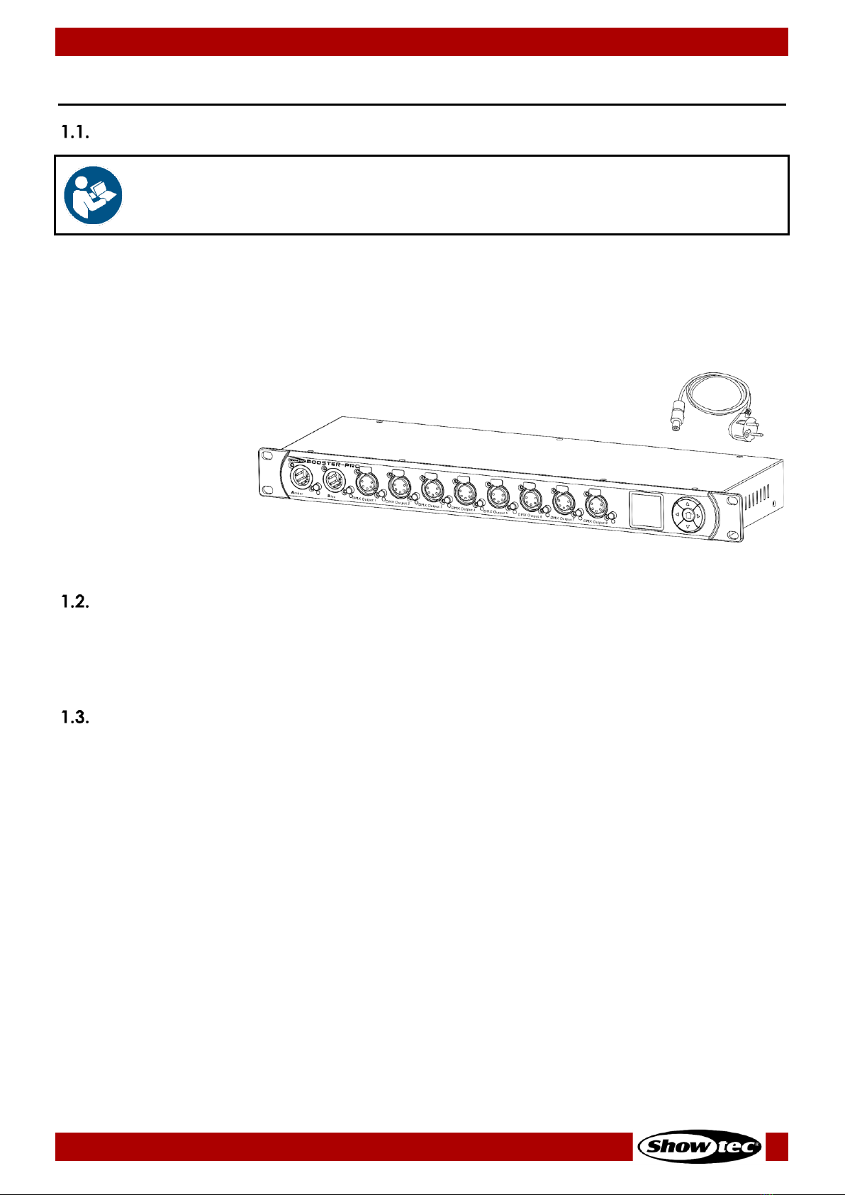
Your shipment includes:
●Showtec Booster Pro
●Schuko to pro-power
cable (1,5 m)
●User manual
Fig. 01
Intended Use
This device is intended for use as a DMX splitter/booster. It is suitable only for indoor installation. It is not
suitable for households.
Any other use, not mentioned under intended use, is regarded as non-intended and incorrect use.
Text Conventions
Throughout the user manual the following text conventions are used:
●Buttons: All buttons are in bold lettering, for example “Press the UP/DOWN buttons”
●References: References to chapters and parts of the device are in bold lettering, for example:
“Refer to 2. Safety”, “press the power switch (03)”
●0–255: Defines a range of values
●Notes: Note: (in bold lettering) is followed by useful information or tips

5
Booster Pro
Product code: 50789
Symbols and Signal Words
Safety notes and warnings are indicated throughout the user manual by safety signs.
Always follow the instructions provided in this user manual.
DANGER
Indicates an imminently hazardous situation which, if not avoided, will result in
death or serious injury.
WARNING
Indicates an imminently hazardous situation which, if not avoided, could result
in death or serious injury.
CAUTION
Indicates a potentially hazardous situation, which, if not avoided, may result in
minor or moderate injury.
Attention
Indicates important information for the correct operation and use of the
product.
Important
Read and observe the instructions in this document.
Electrical hazard
Provides important information about the disposal of this product.
Symbols on the Information Label
This product is provided with an information label. The information label is located on the bottom plate of
the device.
The information label contains the following symbols:
This device is designed for indoor use.
This device shall not be treated as household waste.
Caution: Risk of electric shock. Disconnect input power before opening.
Warning: This appliance must be earthed.
2. Safety
Important
Read and follow the instructions in this user manual before installing, operating or
servicing this product.
The manufacturer will not accept liability for any resulting damages caused by the non-observance of
this manual.

6
Booster Pro
Product code: 50789
Warnings and Safety Instructions
DANGER
Danger for children
For adult use only. The device must be installed beyond the reach of children.
●Do not leave various parts of the packaging (plastic bags, polystyrene foam, nails, etc.) within
children’s reach. Packaging material is a potential source of danger for children.
DANGER
Electric shock caused by short-circuit
This device falls under IEC protection class I.
●Make sure that the device is electrically connected to ground (earth). Connect the device only to a
socket-outlet with ground (earth) connection.
●Do not cover the ground (earth) connection.
●Do not bypass the thermostatic switch or fuses.
●For replacement use fuses of the same type and rating only.
●Do not let the power cable come into contact with other cables. Handle the power cable and all
connections with the mains with caution.
●Do not modify, bend, mechanically strain, put pressure on, pull or heat up the power cable.
●Make sure that the power cable is not crimped or damaged. Examine the power cable periodically
for any defects.
●Do not immerse the device in water or other liquids. Do not install the device in a location where
flooding may occur.
●Do not use the device during thunderstorms. Disconnect the device from the electrical power supply
immediately.
WARNING
Electric shock caused by dangerous voltage inside
There are areas within the device where dangerous touch voltage may be present.
●Do not open the device or remove any covers.
●Do not operate the device if the covers are open.
●Disconnect the device from electrical power supply before service and maintenance, and when the
device is not in use.
Attention
Power supply
●Before connecting the device to the power supply, make sure that the current, voltage and
frequency match the input voltage, current and frequency specified on the information label on the
device.
●Make sure that the cross-sectional area of the extension cords and power cables is sufficient for the
required power consumption of the device.
7
Booster Pro
Product code: 50789
Attention
General safety
●Do not block the ventilation openings. Without proper heat dissipation and air circulation, the
internal components may overheat. This can result in product damage.
●Do not shake the device. Avoid brute force when installing or operating the device.
●If the device is dropped or struck, disconnect the device from the electrical power supply
immediately.
●If the device is exposed to extreme temperature variations (e.g. after transportation), do not switch it
on immediately. Let the device reach room temperature before switching it on, otherwise it may be
damaged by the formed condensation.
●If the device fails to work properly, discontinue the use immediately.
Attention
This device shall be used only for the purposes it is designed for.
This device is designed to be used as a DMX splitter/booster. Any incorrect use may lead to hazardous
situations and result in injuries and material damage.
This device does not contain user-serviceable parts. Unauthorized modifications to the device will render
the warranty void. Such modifications may result in injuries and material damage.
Attention
Do not expose the device to conditions that exceed the rated IP class conditions.
This device is IP20 rated. IP (Ingress Protection) 20 class provides protection against solid objects greater
than 12 mm, such as fingers, and no protection against harmful ingress of water.
Requirements for the User
This product may be used by ordinary persons. Maintenance and installation may be carried by ordinary
persons. Service shall be carried out only by instructed or skilled persons. Contact your Highlite
International dealer for more information.
Instructed persons have been instructed and trained by a skilled person, or are supervised by a skilled
person, for specific tasks and work activities associated with the service of this product, so that they can
identify risks and take precautions to avoid them.
Skilled persons have training or experience, which enables them to recognize risks and to avoid hazards
associated with the service of this product.
Ordinary persons are all persons other than instructed persons and skilled persons. Ordinary persons
include not only users of the product but also any other persons that may have access to the device or
who may be in the vicinity of the device.

8
Booster Pro
Product code: 50789
3. Description of the Device
The Showtec Booster Pro is an optically isolated DMX splitter and booster. It is equipped with 2 inputs
which can be patched to 8 selectable outputs. The device supports RDM and merging. It also offers real-
time DMX monitoring of the input and output ports. In case of an error, an acoustic signal will warn the
user.
Front View
Fig. 02
01) 4 x mounting openings (for installation in a 19-inch rack)
02) 5-pin DMX connector IN (Input A, Amber)
03) Input port button (Input A)
04) LED indicator (Input A)
05) 5-pin DMX connector IN (Input B, Blue)
06) Input port button (Input B)
07) LED indicator (Input B)
08) 8 x 5-pin DMX connectors OUT (Outputs 1–8)
09) 8 x output port buttons (Outputs 1–8)
10) 8 x LED indicators (Outputs 1–8)
11) Control panel: OLED display and control buttons
Back View
Fig. 03
12) Power switch
13) Pro-power connector IN
14) Fuse F1 A, 250 V
15) Ground (earth) connection
9
Booster Pro
Product code: 50789
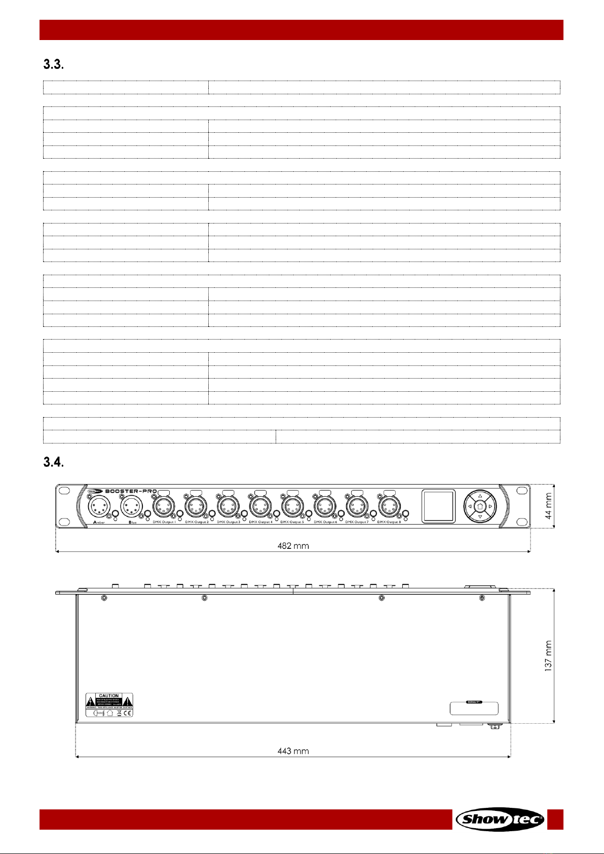
Product Specifications
Model:
Booster Pro
Electrical:
Input voltage:
100–240 V AC, 50/60 Hz
Power consumption:
5 W
Fuse:
F1 A, 250 V
Physical:
Dimensions:
482 x 137 x 44 mm (L x W x H)
Weight:
2 kg
Operation and control:
Control protocols:
DMX-512, RDM
Control panel:
OLED display and buttons
Connections:
Power connections:
Pro-power connector IN
Input connections:
2 x 5-pin DMX connectors IN
Output connections:
8 x 5-pin DMX connectors OUT (optically isolated)
Construction:
Housing:
Metal and flame-retardant plastic
Color:
Black
IP rating:
IP20
Cooling:
Natural heat dissipation
Thermal:
Maximum ambient temperature ta:
55 °C
Dimensions
Fig. 04
Fig. 05

10
Booster Pro
Product code: 50789
4. Installation
Safety Instructions for Installation
Attention
Make sure there is enough space for ventilation around the device.
●Do not block the ventilation openings. Without proper heat dissipation and air circulation, the
internal components may overheat. This can result in product damage.
●Do not install near equipment that produces heat, for example amplifiers.
Installation Site Requirements
●The device must be installed only indoors.
●The device can be placed on a flat surface or mounted in a standard 19-inch rack.
●The maximum ambient temperature ta= 55 °C must never be exceeded.
●The relative humidity must not exceed 50 % with an ambient temperature of 50 °C.
Rack Mounting
The device can be mounted in a standard 19-inch rack. The device requires 1 rack unit (RU) of space,
which is 44,45 mm high.
Make sure that the rack is sufficiently secured to prevent it from becoming unstable or falling over.
To mount the device in a two-post rack, follow the steps below:
01) Insert 4 cage nuts in the openings on the rack posts where you want to mount the device.
02) Position the device in front of the rack posts so that the 4 mounting openings (01) on the flanges face
the openings on the rack posts with cage nuts.
03) Using a screwdriver, mount the device to the rack posts with 4 screws.
Connecting to Power Supply
DANGER
Electric shock caused by short-circuit
The device accepts AC mains power at 100–240 V and 50/60 Hz. Do not supply power at any other
voltage or frequency to the device.
This device falls under IEC protection class I. Make sure that the device is always electrically connected
to the ground (earth).
Before connecting the device to the socket-outlet:
●Make sure that the power supply matches the input voltage specified on the information label on
the device.
●Make sure that the socket-outlet has ground (earth) connection.
Connect the device to the socket-outlet with the power plug.
11
Booster Pro
Product code: 50789
5. Setup
Warnings and Precautions
Attention
Connect all data cables before supplying power.
Disconnect power supply before connecting or disconnecting data cables.
DMX Connection
DMX-512 Protocol
DMX-512 is a communication protocol used to control stage lighting and effects.
Devices on a serial data link must be daisy-chained in a single line. To comply with the TIA-485 standard,
no more than 32 devices should be connected on one data link.
In order to connect more than 32 devices on one data link, you can use a DMX optically isolated
splitter/booster, such as the Booster Pro. If no splitter/booster is used, this may result in deterioration of the
DMX signal.
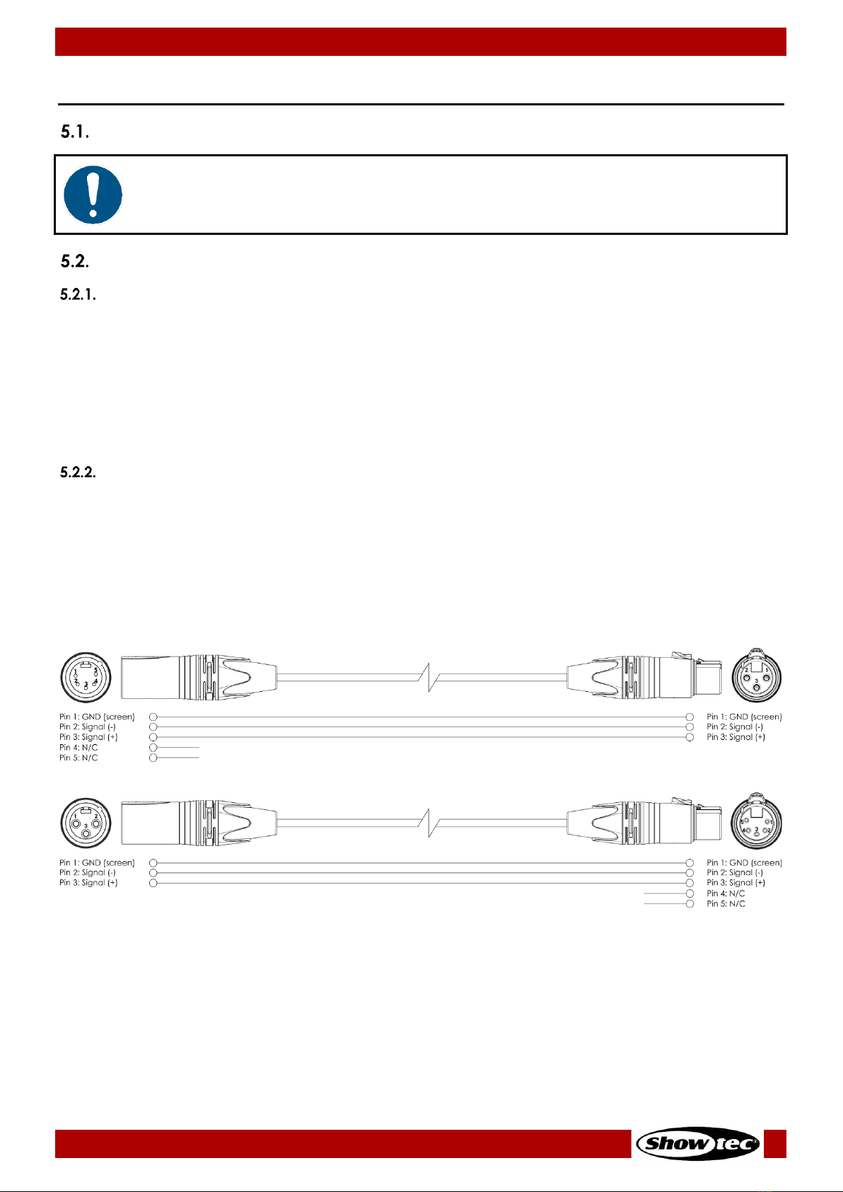
DMX Cables
Shielded twisted-pair cables with 5-pin XLR connectors must be used for reliable DMX connection. You
can purchase DMX cables directly from your Highlite International dealer or make your own cables.
If you use XLR audio cables for DMX data transmission, this may lead to signal degradation and unreliable
operation of the DMX network.
When you make your own DMX cables, make sure that you connect the pins and wires correctly as
shown in Fig. 06.
Fig. 06
12
Booster Pro
Product code: 50789
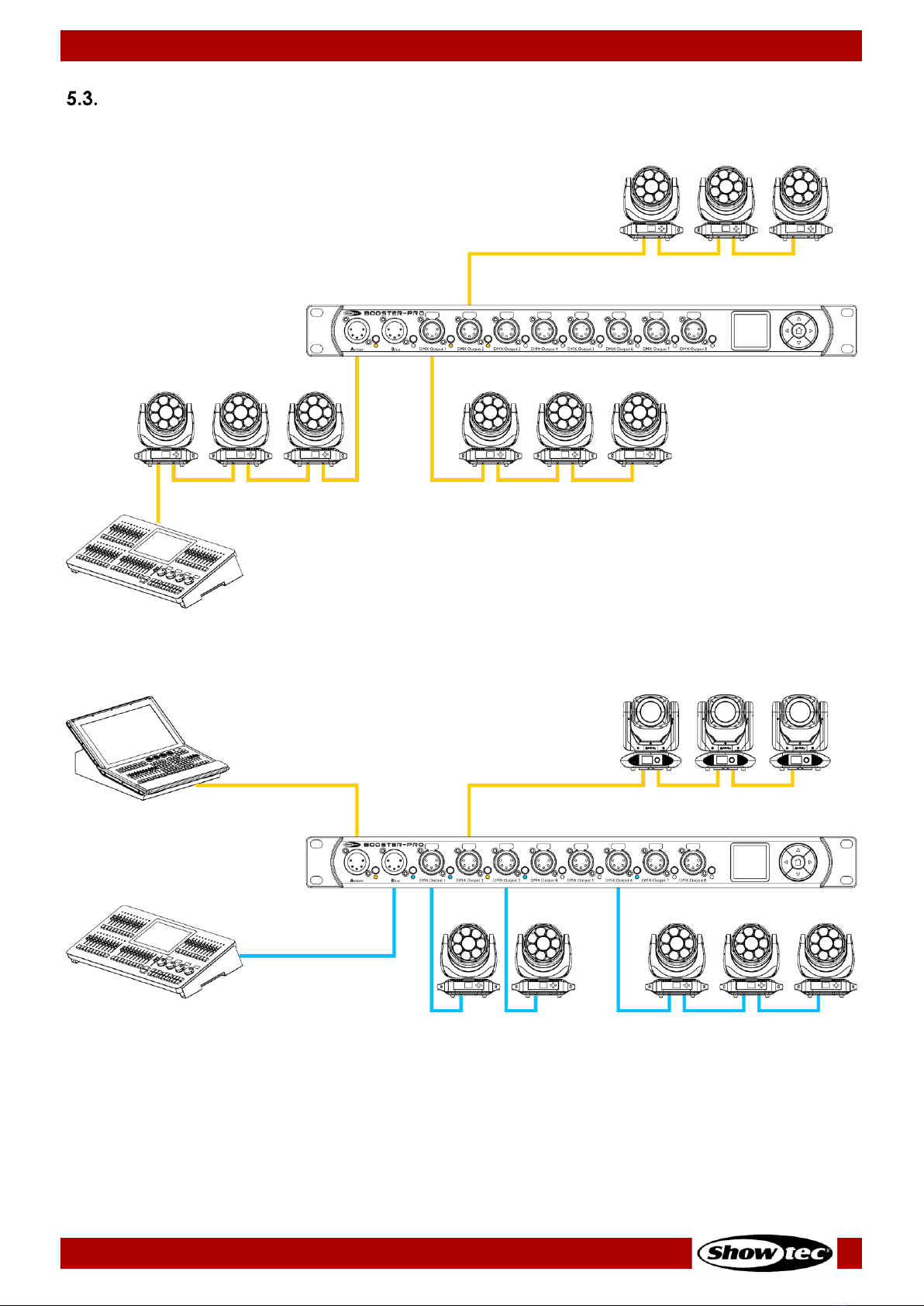
Setup Examples
A typical setup with the device used as a splitter/booster:
Fig. 07
A typical setup with 2 controllers:
Fig. 08
13
Booster Pro
Product code: 50789
6. Operation
Safety Instructions for Operation
Attention
This device must be used only for the purposes it is designed for.
This device is intended for use as a DMX splitter/booster. It is suitable only for indoor installation. It is not
suitable for households.
Any other use, not mentioned under intended use, is regarded as non-intended and incorrect use.
Attention
Power supply
Before connecting the device to the power supply, make sure that the current, voltage and frequency
match the input voltage, current and frequency specified on the information label on the device.
Start-up
The device has a power switch.
●Press the power switch (12)in ON position to turn the device on.
●Press the power switch (12)in OFF position to turn the device off.
At start-up the OLED display shows the home screen. The home screen provides side by side information
about the connection status of Input A and Input B and the port mode. See 6.4.1. Home Screen on
page 14 for more information.
Note:
If no button is pressed, after 10 seconds of inactivity the display will return to the home screen and after
30 more seconds it will turn off. Press any button to turn the display on.
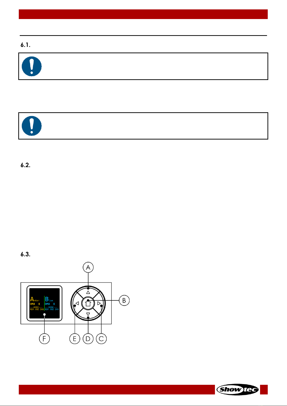
Control Panel
A) UP button
B) HOME button
C) ENTER button
D) DOWN button
E) MENU button
F) OLED display
Fig. 09
●Use the HOME button to show the home screen.
14
Booster Pro
Product code: 50789
●Use the MENU button to open the main menu, to exit the current submenu and to return to the main
menu.
●Use the UP/DOWN buttons to navigate through the menus and to scroll through the available
characters/numbers.
●Use the ENTER button to open the desired menu, to confirm your choice or to set the currently
selected character/number.
Input Ports Monitoring
The device has 2 input ports: Input A (Amber) and Input B (Blue). The status of the input ports is shown on
the display. The information about Input A is displayed in amber color and the information about Input B
in blue. The information is available on the home screen or it can be accessed via the input port buttons
and via the main menu.
Home Screen
The home screen provides side by side information about the connection status of Input A and Input B
and the port mode. Press the HOME button to access the home screen.
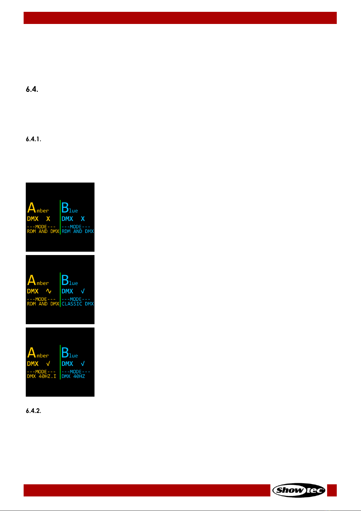
Home screen examples:
Input A (Amber):
●DMX signal: (X) not present
●Mode: RDM and DMX
Input B (Blue):
●DMX signal: (X) not present
●Mode: RDM and DMX
Input A (Amber):
●DMX signal: (~) weak/distorted
●Mode: RDM and DMX
Input B (Blue):
●DMX signal: (√) present
●Mode: Classic DMX
Input A (Amber):
●DMX signal: (√) present
●Mode: DMX at 40 frames per second, frame integrity on
Input B (Blue):
●DMX signal: (√) present
●Mode: DMX at 40 frames per second, frame integrity off
Quick Access
The input port buttons (03) and (06) provide quick access to the Status Information submenu for
respectively Input A and Input B.
To view the status of Input A (Amber), press the input port button (03). To view the status of Input B (Blue),
press the input port button (06). The screen provides information about the presence of DMX signal, the
DMX channel and frame rate, the port mode and the assigned outputs to the respective input port.

15
Booster Pro
Product code: 50789
To view the second screen with information, press the UP/DOWN buttons on the control panel (11). The
second screen provides information about the presence of DMX signal and the incoming DMX values at
the respective input port.
See 6.9.1.3. Status Information on pages 21–22 and 6.9.2.3. Status Information on pages 23–24 for more
information.
Access via the Main Menu
You can monitor the status of Input A and Input B from the main menu.
Refer to 6.9.1.3. Status Information on pages 21–22 for monitoring the status of Input A.
Refer to 6.9.2.3. Status Information on pages 23–24 for monitoring the status of Input B.
Output Ports Configuration
The device has 8 output ports. Each port can be assigned to Input A or Input B, or to both ports with the
merge function. You can configure the output ports via the output port button or via the main menu.
Quick Access
The output port buttons (09) provide quick access to the configuration of the 8 output ports. Press the
output port button repeatedly to select one of the following 3 configuration options:
●Connect Output 1 to Input A.
The LED indicator (10), located to the right of the port, will light in amber.
●Connect Output 1 to Input B.
The LED indicator (10), located to the right of the port, will light in blue.
●Connect Output 1 to Input A and Input B via the merge function.
You can additionally configure the merging options via the main menu.
Refer to 6.6. Merge Function on page 16 for explanation of the
configuration options and to 6.9.3. Merge on pages 24–25 for the
configuration settings.
The LED indicator (10), located to the right of the port, will light in magenta.

16
Booster Pro
Product code: 50789
Access via the Main Menu
You can configure the 8 output ports from the main menu. The configuration options are the same as via
the quick access. Refer to 6.9.4. Outputs on page 25 for more information.
Merge Function
The Booster Pro supports merging. Each output port can be configured to merge the DMX packets
received at Input A and Input B. See 6.9.3. Merge on pages 24–25 for the configuration settings.
The device supports the following merging modes:
HTP (Highest Takes Precedence)
When the HTP (Highest Takes Precedence) mode is selected, the DMX packets received at Input A and
Input B are compared and the DMX packet with the highest value is sent to the respective output port.
For example, if a lighting controller, connected to Input A, sends a dimmer value at 50 % and a lighting
controller, connected to Input B, sends a dimmer value at 80 %, at the output port there will be send
80 %. If you change the dimmer value at Input B to 0 %, the output value will be 50 %, sent by Input A, as
50 % is a higher value than 0 %.
HTP mode is recommended for controlling light intensity.
LTP (Latest Takes Precedence)
If you need to control parameters as color, pan and tilt, HTP mode will be a problem, as non-intensity
channels do not have ‘higher’ or ‘lower’ values. The color red is not higher or lower than green, and
gobo 1 is not higher or lower than gobo 2. Therefore, when working with effect lights or moving lights, it is
recommended to use LTP (Latest Takes Precedence) mode.
The LTP (Latest Takes Precedence) mode means that the most recently received DMX packet from Input
A and Input B will be sent to the respective output port.
For example, with two lighting controllers connected (Input A and B), the last lighting controller that
made any change will take precedence and will control the output.
A + B
With A + B mode the DMX channel is split into 2 parts. The first part is reserved for Input A and the second
part is reserved for Input B. The DMX packets received at the inputs are not combined. For example,
Input A sends DMX packets up to channel 256 and Input B starts at channel 257 on the same universe.
The starting address for Input B is user-programmable.
Backup
In backup mode Input A sends continuously DMX packets to the output. If Input A fails, Input B takes over
automatically. Input B serves as a backup in case of failure of Input A.

17
Booster Pro
Product code: 50789
LED Statuses
Each DMX input and output is provided with a LED indicator. The color of the LED for Input A is amber,
and for Input B is blue.
The LED indicator (04) for Input A (Amber) has the following statuses:
●Steady: DMX signal is present at Input port A
●Flashing slowly: The Input A port is not selected and there is no DMX signal
present at the port
●Flashing quickly: The Input A port is selected with the input port button (03) or
via the menu
●Flashing red: DMX signal is faulty
●Flashing white: The port has received an RDM command to identify itself
Fig. 10
The LED indicator (07) for Input B (Blue) has the following statuses:
●Steady: DMX signal is present at Input port B
●Flashing slowly: The Input B port is not selected and there is no DMX signal
present at the port
●Flashing quickly: The Input B port is selected with the input port button (06) or
via the menu
●Flashing red: DMX signal is faulty
●Flashing white: The port has received an RDM command to identify itself
Fig. 11
The LED indicators (10)for the output ports have the following statuses:
●Amber color: The output port is connected to Input A (Amber)
●Blue color: The output port is connected to Input B (Blue)
●Magenta color: The merge function for the output port is activated
●Steady: DMX signal is present at the output port
●Flashing slowly: The output port is not selected and there is no DMX signal
present at the port
●Flashing quickly: The output port is selected with the output port button (09)
or via the menu
●Flashing white: The port has received an RDM command to identify itself
Fig. 12

18
Booster Pro
Product code: 50789
Menu Overview

19
Booster Pro
Product code: 50789
This manual suits for next models
1
Table of contents
Other Show Tec Cables And Connectors manuals


