ShowMojo MojoLock User manual
Note:
1st step if hole is predrilled
Note: To drive in latch, drill hole size indicated on template and press latch until it is flush with door edge.
U
P
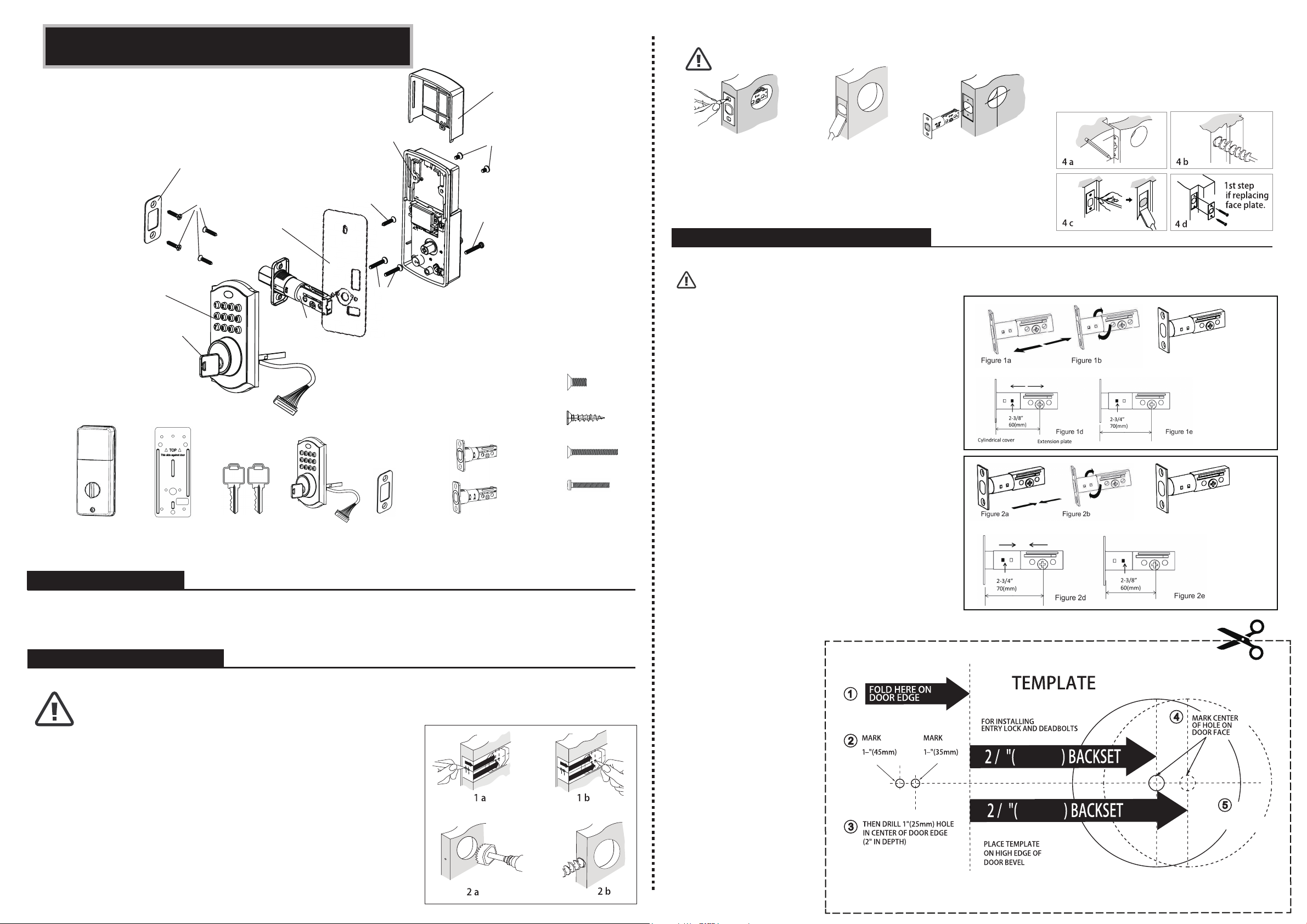
1. Tools Required
Lorem ipsum dolor sit amet, consec
2. Drilling Hole in Door
Lorem ipsum dolor sit amet, consectetuer adipi
3. Adjusting Deadbolt Latch Set
IMPORTANT!
8
60mm
3
FOR
DOOR
3
4
DRILL
2-1/8"(54mm)
HOLE
4
70mm
3
3
8
FOR
DOOR
MojoLock
• Please read and understand this entire manual before attempting to assemble, operate, or install.
• Do not use electric screwdriver, only hand tighten screws with a Phillips Head screwdriver.
• DO NOT OVER TIGHTEN SCREWS.
• If your door has pre-drilled holes, skip to step 3c.
1. Mark Door for Drilling
a. Start 36" from floor. Fold and apply template to high edge of door.
b. Mark center hole on door face through guide on template for 2-3/8"
(60mm) or 2-3/4" (70mm) backset.
2. Drill Holes
a. Drill 2-1/8" hole through door face as marked for lock set.
b. Drill 1" hole in center of door edge for latch.
3. Mark the Jamb Hole Location
a. Insert latch in hole, keeping it parallel to face of door. Mark outline and
remove latch.
b. Chisel 1/8" deep or until latch face is flush with door edge.
c. Insert latch and tighten screws.
3 a 3 b 3 c
4. Install Deadbolt Strike Plate into Door Frame
Note: If hole is pre-drilled, skip to step 4d.
a. Mark template from edge of jamb and locate strike opening.
b. Drill 1" hole 1-3/16" deep in door jamb on center line of screws.
c. Outline outside edges of strike. Chisel 1/6" deep for strike or until flush.
d. Install strike and tighten screws. Use 3/4" (19mm) screws.
Note: Deadbolt Latch Set is shipped with the backset set at 2-3/8" (60mm). Backset is the distance between edge
of the door and the center of the lock. Measure the backset on door to confirm before installation.
Do not extend Cylindrical Cover past 2-3/4" (70mm)
1. To convert FROM 2-3/8" (60mm) backset
TO 2-3/4" (70mm) backset:
a. Hold latch with numbers facing forward and thumb
pressing on the bolt (Figure 1a).
b. Rotate the cylinder cover clockwise (Figure 1b).
c. Pull and twist the extension plate all the way
out (Figure 1c).
d. Rotate the cylinder cover counter-clockwise so that
the marking aligns with the 2-3/4" (70mm) position
indicator (Figure 1d).
2. To convert FROM 2-3/4" (70mm) backset
TO 2-3/8" (60mm) backset:
a. Hold latch with numbers facing forward and thumb
pressing on the bolt (Figure 2a).
b. Rotate the cylinder cover clockwise (Figure 2b).
c. Push and twist the extension plate all the way
in (Figure 2c).
d. Rotate the cylinder cover counter-clockwise so that
the marking aligns with the 2-3/8" (60mm) position
indicator (Figure 2d).
Tools required for installation on doors that require drilling:
• Drill • Pencil • 1" (25mm) Drill Bit • Chisel • Philips Head Screwdriver
• Tape Measure • 2-1/8" (54mm) Drill Hole Saw • 1/16" (2mm) Drill Bit • Hammer
Strike Plate
Installation Instructions
Key
Touch Keypad
Assembly
Latch
Mounting Plate
3/4” (19mm) screws (4ea.)
Battery Cover
Interior Assembly
Optional 3/4” (19mm)
screw (1ea.)
1-5/16” (33mm) screws (2ea.)
1” (25mm) screw (1ea.)
5/16” (8mm) screws (2ea.)
1-5/16” (33mm) screws (2ea.)
1” (25mm) screw (1ea.)
5/16” (8mm) screws (2ea.)
Strike Plate
Entry Keys (2ea.)
Interior Assembly Mounting Plate Keypad
Assembly
3/4” (19mm) screws (5ea.)
Deadbolt Latch Set (Adjustable)
2-3/8” (60mm) to 2-3/4” (70mm)
Your latch is now set
2-3/4" (70mm) backset
Your latch is now set
2-3/8" (60mm) backset
Figure 1c
Figure 2c
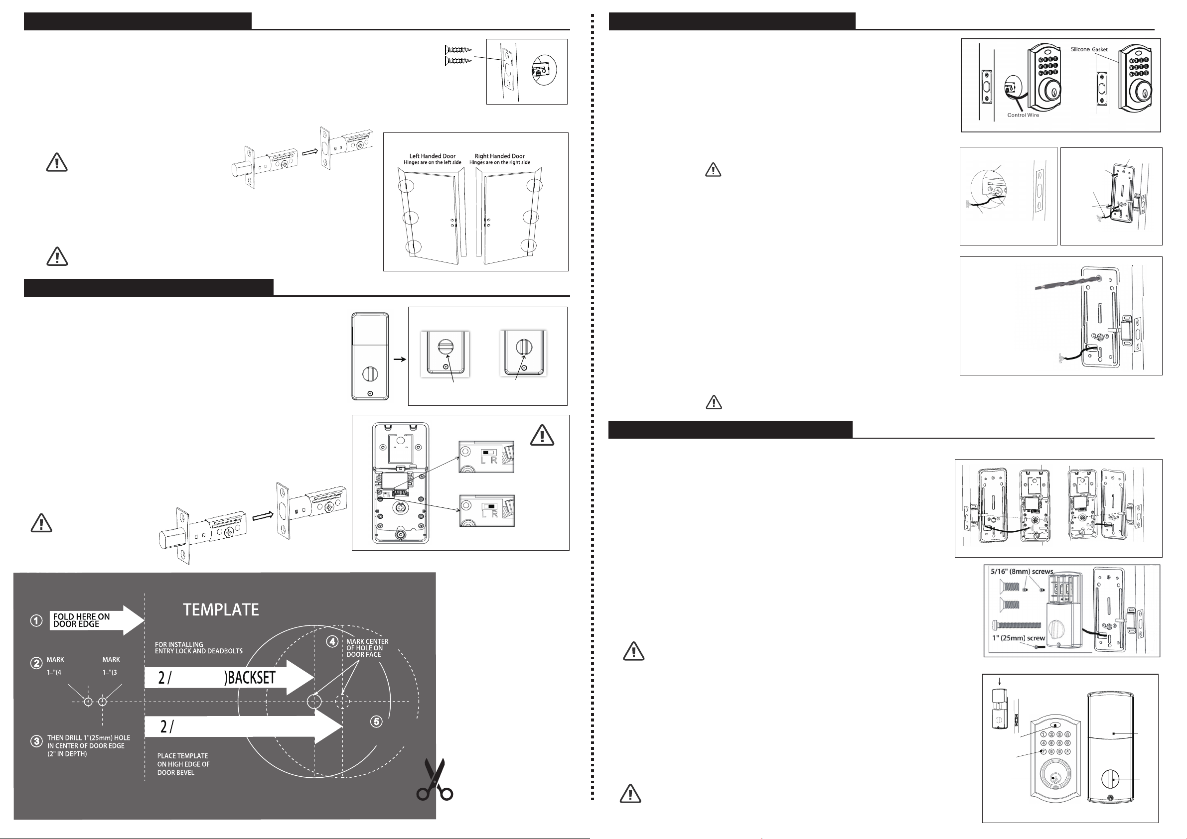
4. Installing Deadbolt Latch Set
Screws (19mm)
Out Swing Door
5. Preparing the Interior Assembly
6. Installing the Exterior Assembly
7. Installing the Interior Assembly
IMPORTANT!
8
"(60mm
3
FOR
0mm)
DOOR
5
8
DRILL
2-1/8"(54mm)
HOLE
4
"(70mm)BACKSET
3
1
8
FOR
0mm)
DOOR
Entry Switch
(Left or Right)
Keypad
Latch Hole
Tail Piece
(Horizontal)
Control
Wire
Control Wire
Left Handed Door
(Horizontal)
Right Handed Door
(Vertical)
a
3. Installing the Deadbolt Latch Set (Philips Head Screwdriver Needed)
a. Insert Deadbolt Latch Set into door edge hole with the word "UP" and the arrow on
the extension plate facing UP. Cross-shaped spindle connector will be at the bottom
of the Deadbolt Latch Set (Figure 3a).
b. Make sure the face plate sits flush with the door. Do not force the latch into the mortise flush.
Chisel out excess material if necessary for a flush fit.
c. Using two 3/4" (19mm) screws provided, screw the latch into the door with a hand-held screwdriver.
DO NOT OVER TIGHTEN.
Note: Deadbolt Latch must be
retracted when installing.
4. Identifying Your Door Handling
a. If the hinges are on the left, your door is Left Handed (Figure 4a).
b. If the hinges are on the right, your door is Right Handed (Figure 4b).
Note: Identify while you are standing outside the door.
5. Unpack the Interior Assembly
a. Remove the battery cover by sliding the cover upward.
b. Locate the screws holding the Mounting Plate to the
Interior Assembly. Remove the screws to release the
Mounting Plate from the Interior Assembly.
6. For Left-Handed Doors
The interior knob goes in the horizontal position (Figure 6a).
Gently move the switch to "L" (Figure 7a).
7. For Right-Handed Doors
The interior knob goes in the vertical position (Figure 6b).
Gently move the switch to "R" (Figure 7b).
Note: Make sure the
Deadbolt Latch is retracted.
8. Installing the Exterior Assembly
Work with the door OPEN for easy access.
a. Unpack the Exterior Assembly. Use care to not scratch the black
circuit board during handling and installation.
b. Check that the Rubber Gasket is properly seated on the
Exterior Assembly (Figure 8a-b).
c. Insert the Exterior Assembly onto the door with the Tail Piece going
through the Deadbolt Latch Set cross-shaped spindle connector in the
HORIZONTAL POSITION. Route the Control Wire through door over
the Deadbolt Latch Set (Figure 8c).
Note: Tail Piece must be positioned horizontal
9. Securing the Exterior Assembly to the Door
a. From the side marked "This side against door", route the Control Wire
through the rectangular slot in the Mounting Plate (Figure 9a-f).
b. Place Mounting Plate against door with Tail Piece passing through
the center hole in the three hole set (Figure 9a-f).
c. Secure the Mounting Plate to the Exterior Assembly using two
1-5/16" (33mm) screws (Figure 9a-f).
d. Tighten with a hand-held Philips Head Screwdriver, leaving loosely
connected (Figure 9a-f).
e. Check that the Rubber Gasket is properly aligned, correct if necessary.
f. Check vertical alignment of the lock (Figure 9a-f).
g. Tighten securely with a hand-held Philips Head Screwdriver.
DO NOT OVER TIGHTEN.
10. Optional Installation
a. Using a 1/16” (2mm) drill bit, drill a pilot hole in your door using the
Mounting Plate upper hole as a guide (Figure 10a).
b. Insert one 3/4" (19mm) screw into newly drilled hole and tighten.
Note: Lock and unlock using the key to see if the Deadbolt Latch is opening and closing easily.
Figure 10a
Figure 8c Figure 9a-f
Figure 8a-b
Figure 3a
Figure 4a
Figure 6a Figure 6b
Figure 7a
Figure 7b
11. Attach the Control Wire and the Closed-Door Sensor to the Interior Assembly
a. Use care to attach the Control Wire male plug of the lock and the
closed-door sensor to the Interior Assembly female socket connector
(Figure 11a).
b. For Left-Handed Doors, attach the Control Wire male plug of the
closed-door sensor to the Left Interior Assembly female socket.
c. For Right-Handed Doors, attach the Control Wire male plug of the
closed-door sensor to the Right Interior Assembly female socket.
12. Attach the Interior Assembly to Door
a. Position the Interior Assembly over the Tail Piece and push the Interior
Assembly against the door (Figure 12a-b).
b. Using two 5/16" (8mm) screws and one 1" (25mm) screw, attach the
Interior Assembly to the Mounting Plate (Figure 12a-b).
DO NOT OVER TIGHTEN.
Note: Lock and unlock using Interior Knob to see
if the latch is opening and closing easily.
13. Installing Batteries
a. Insert 4 AA high-quality Alkaline batteries into the Battery Compartment
in the direction noted +/- on the Compartment. The Lock will beep 2 times,
the keypad will illuminate blue, and the Light Indicator will flash green twice
to signify that it has received power (Figure 13a).
b. Slide the Battery Cover down into the track on the Interior Assembly to
cover the batteries (Figure 13b).
Note: Do not touch Keypad until the blue light turns off.
Do not use recharchable batteries or non-alkaline batteries.
Deadbolt Latch Extended Deadbolt Latch Retracted
Deadbolt Latch Extended Deadbolt Latch Retracted
Light Indicator
Battery
Cover
Interior
Knob
Interior AssemblyExterior Assembly
Figure 13a Figure 13b
Physical
Key
Figure 12a-b
Figure 11a
Right handed door view
Mounting Plate
3/4”(19mm) screw
(Optional Installation)
1-5/16”(33mm)
screws
Popular Door Lock manuals by other brands

U-tec
U-tec Ultraloq U-Bolt WiFi Installation and user guide

Amplicom
Amplicom RingFlash 250 operating instructions

Digitus Biometrics
Digitus Biometrics db Enline Installation and user manual

Kaadas
Kaadas K7 installation guide

Assa Abloy
Assa Abloy CLIQ eCLIQ Connect key operating instructions

Toledo
Toledo V190TBIUS15 quick start guide


