manuals.online logo
Brands
  1. Home
  2. •
  3. Brands
  4. •
  5. tell
  6. •
  7. Door Lock
  8. •
  9. tell CL600 Administrator guide

tell CL600 Administrator guide

Tell Manufacturing | A Division of Spectrum Brands Inc.Tell Manufacturing | A Division of Spectrum Brands Inc. 4 1 1-800-433-4047 | TEL035002-CL600-110320
MANY CODES TO CHOOSE FROM
The CL600 range has been designed so the code can be
changed on the door in seconds. The code chamber (models
600, 610 and 620) consists of 13 buttons and a ‘C’ button which
is used to re-set (clear)the code chamber after an incorrect
entry, and must always be used as the rst digit of a code.
Buttons may only be used ONCE in a code. For example C1212
is NOT possible.
The CL600 ranges code or combination, can be entered in any order or sequence; eg C1234 can be
C4321 or C1342 or whatever sequence is most convenient to remember.
With 13 buttons, a total of 8,191 different codes are available, any of which can be entered in any
sequence.
The total is arrived at as follows:
Note: Most people will set the code in the range of 4 to 7 digits, and the total number of codes in this range
is 5,434. The lock is supplied with a random factory set code (see code card inside box). At any time
this can be quickly changed to a new code of your choice. Typically codes are 4 to 7 digits long.
Shorter codes are possible (1-2 digits) but are not recommended.
Access Under Control – The Simple and Easy Way
CODE CHANGE GUIDE
CL600 MECHANICAL LOCK
DIMENSIONS
Features
• On door code change in seconds.
• Inside handle always retracts the latch for exit.
• Weather resistant.
• Tamper resistant, with stainless steel buttons,
and clutch protection if the outside handle is
forced.
• Reversible handles.
• Easy code change as often as required.
• Fits doors between 1 3⁄8” (35mm) and 2 3⁄8”
(60mm) thick without modication.
Maintenance
No maintenance of the working parts is
necessary. DO NOT OIL. To maintain the nish
the lock should be cleaned regularly with a soft
cloth. A silicone spray or similar should be used
to provide a protective lm against grit and grime.
Tell Manufacturing | A Division of Spectrum Brands Inc. 32
CODE CHANGE INSTRUCTIONS
The CL600 range offers signicant advantages over other similar mechanical digital locks by
allowing the code to be changed in seconds on the door.
1. Choose your code.
2. Insert key and turn anticlockwise to stop for right hand hung doors, or clockwise to stop for left hand
hung doors. Fig 1.
3. Push the code change tool onto each button in turn, pushing in the buttons approx 3/32” (2mm) turn
anticlockwise 180°. All buttons should now be in the non code position.
4. Test that all buttons are in non code position (perform step 6 before testing buttons) then depress the
lever handle which should retract the latch. If latch cannot be retracted press ‘C’ button and repeat
step 3.
5. To select a button as a code button, push code tool over button. Press in button with tool approx 3/32”
(2mm) and turn clockwise 180°. Fig 2.
6. Now turn the key clockwise for right hand hung doors, or anticlockwise for left hand hung doors
retracting the latch which will re-lock the code buttons. Fig 3.
7. Return the key to center and remove.
8. Before closing door test code.
Note: Models 605, 615, 625 only – Before changing code press the ‘Z’ and ‘C’ button to ensure that the
lock is not in free passage mode.
1. Remove handle and cylinder cover.
2. Turn Key 90° anticlockwise and remove the
cylinder from boss
3. To replace cylinder, reinsert and turn 90°
clockwise. Replace the cylinder cover and
handle.
*If intending to use a cylinder from a different
manufacturer it is advisable to conrm
beforehand that the new cylinder will t the
boss.
Note that the CL600 uses a 6 pin screw cap
cylinder.
If using a screw cap cylinder other than
supplied, the tail piece from the Codelocks
screw cap cylinder will need to be tted as
follows:
4. Hold down the control pin in the end of the
cylinder and unscrew the cap.
Caution! Do not insert the key in the cylinder
once you have removed the screw cap!
5. Ret the tailpiece, hold down the control pin and
screw the cap on fully without tightening. Ensure
the control pin projects to lock the cap.
Test the key operation
If the key is difcult to insert, or tight when turning,
then the cap may be too tight. Loosen the cap one
notch at a time and try the key again. If the key
inserts and turns OK, but is difcult to remove, then
the cap may be too loose.
Tighten up the cap one notch at a time.
Adjust the cap until the key inserts, turns and
removes easily.
REMOVAL OF FRONT LOAD CYLINDERS TO RE-PIN OR REPLACE WITH CYLINDERS.

Other tell Door Lock manuals

tell CL600 User manual

tell

tell CL600 User manual

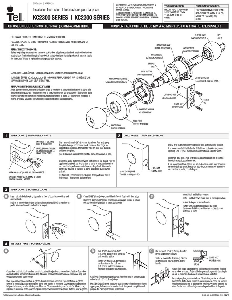
tell KC2300 Series User manual

tell

tell KC2300 Series User manual

tell KC2300 Series User manual

tell

tell KC2300 Series User manual

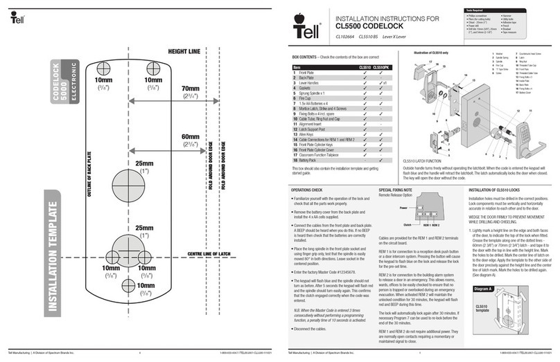
tell CODELOCK CL5500 Series User manual

tell

tell CODELOCK CL5500 Series User manual

Popular Door Lock manuals by other brands

Kwikset Burbank Quick installation guide

Kwikset

Kwikset Burbank Quick installation guide

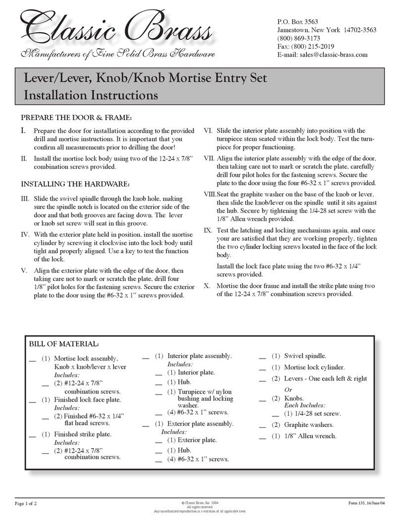
Classic Brass Lever/Lever installation instructions

Classic Brass

Classic Brass Lever/Lever installation instructions

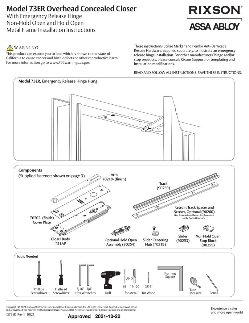
Assa Abloy Rixson 73ER manual

Assa Abloy

Assa Abloy Rixson 73ER manual

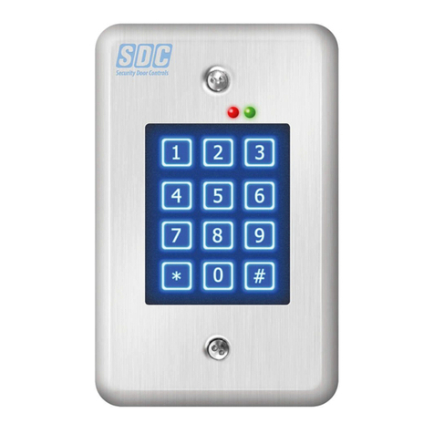
SDC EntryCheck 918 installation instructions

SDC

SDC EntryCheck 918 installation instructions

CODELOCKS CL500 Code change guide

CODELOCKS

CODELOCKS CL500 Code change guide

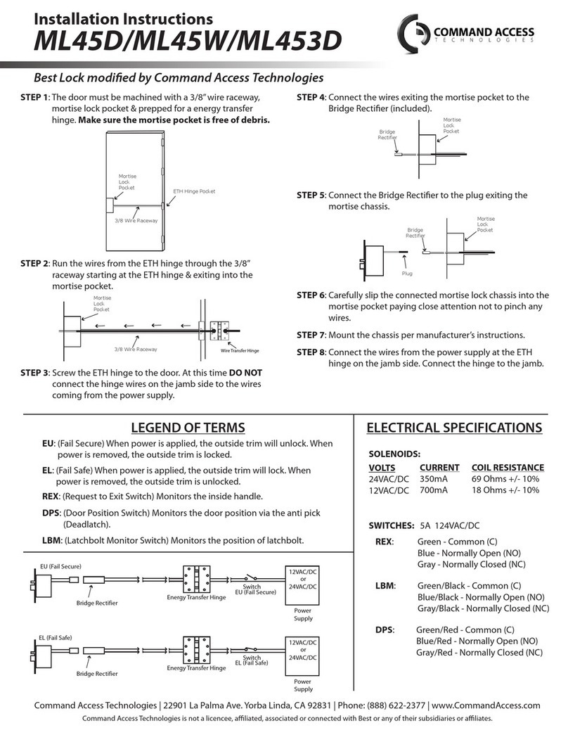
Command access ML45D installation instructions

Command access

Command access ML45D installation instructions

Ezset PMR30S31 user guide

Ezset

Ezset PMR30S31 user guide

Link SmartLINK M 13 85 Operation and installation manual

Link

Link SmartLINK M 13 85 Operation and installation manual

Miles Nelson Doorbot user manual

Miles Nelson

Miles Nelson Doorbot user manual

Allegion Falcon Security Strike Installation

Allegion

Allegion Falcon Security Strike Installation

Yale 5400 Series installation instructions

Yale

Yale 5400 Series installation instructions

DORTRONICS SYSTEMS 6420 Series Mounting instructions

DORTRONICS SYSTEMS

DORTRONICS SYSTEMS 6420 Series Mounting instructions

Milocks BLEF installation guide

Milocks

Milocks BLEF installation guide

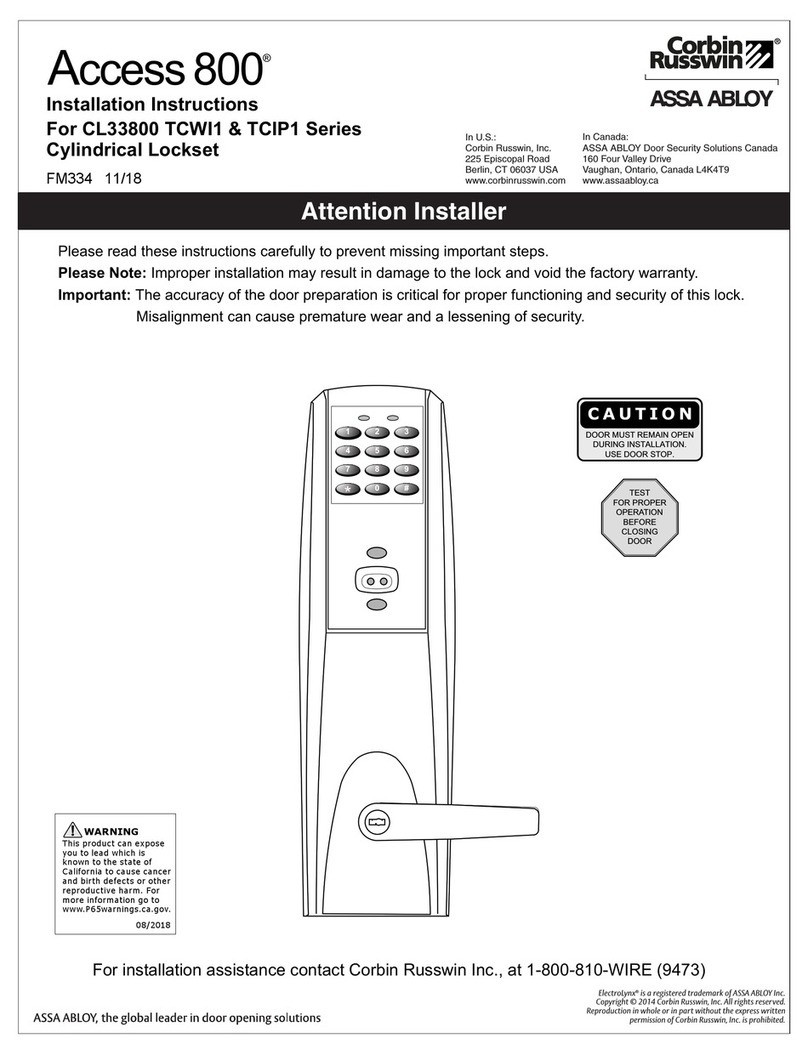
Assa Abloy Corbin Russwin Access 800 Series installation instructions

Assa Abloy

Assa Abloy Corbin Russwin Access 800 Series installation instructions

RUDO P Series manual

RUDO

RUDO P Series manual

COMPX RegulatoR instruction manual

COMPX

COMPX RegulatoR instruction manual

Dr. Hahn VL-Band installation instructions

Dr. Hahn

Dr. Hahn VL-Band installation instructions

Moniteq CC-8946 instruction manual

Moniteq

Moniteq CC-8946 instruction manual

manuals.online logo
manuals.online logoBrands
  • About & Mission
  • Contact us
  • Privacy Policy
  • Terms and Conditions

Copyright 2025 Manuals.Online. All Rights Reserved.