manuals.online logo
Brands
  1. Home
  2. •
  3. Brands
  4. •
  5. Shure
  6. •
  7. Amplifier
  8. •
  9. Shure ILP-1 User manual

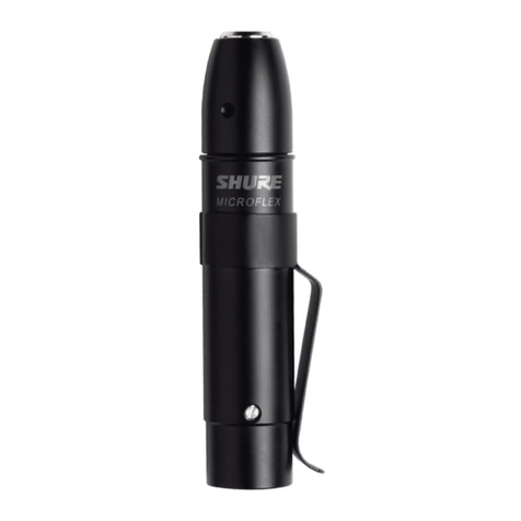
Shure ILP-1 User manual

Other Shure Amplifier manuals

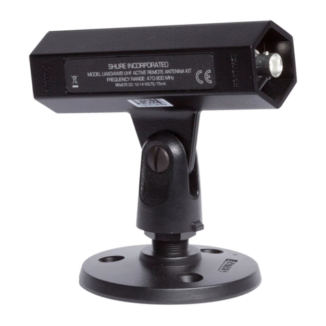
Shure UA834WB User manual

Shure

Shure UA834WB User manual

Shure UA834 User manual

Shure

Shure UA834 User manual

Shure UA845 User manual

Shure

Shure UA845 User manual

Shure Microflex RK100PK User manual

Shure

Shure Microflex RK100PK User manual

Shure M64A User manual

Shure

Shure M64A User manual

Shure SHA900 User manual

Shure

Shure SHA900 User manual

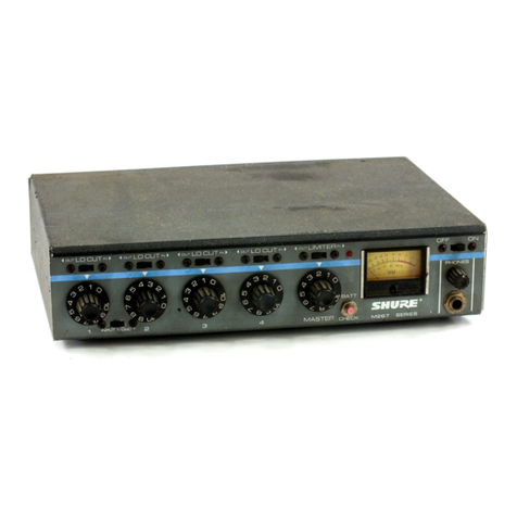
Shure M267 User manual

Shure

Shure M267 User manual

Shure AXIENT AXT630 User manual

Shure

Shure AXIENT AXT630 User manual

Shure FP23 User manual

Shure

Shure FP23 User manual

Shure M64 User manual

Shure

Shure M64 User manual

Shure FP11 User manual

Shure

Shure FP11 User manual

Shure SHA900 User manual

Shure

Shure SHA900 User manual

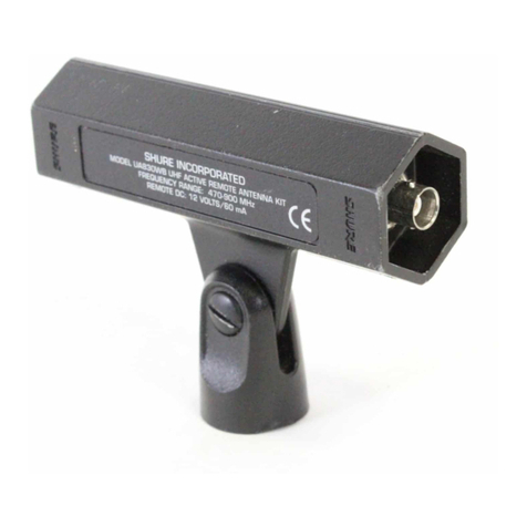
Shure UA830 User manual

Shure

Shure UA830 User manual

Shure (R) FP22 User manual

Shure

Shure (R) FP22 User manual

Shure SR10 Operation manual

Shure

Shure SR10 Operation manual

Shure Microflex RK100PK User manual

Shure

Shure Microflex RK100PK User manual

Shure RK183PK User manual

Shure

Shure RK183PK User manual

Shure Solo-Phone SA-1F User manual

Shure

Shure Solo-Phone SA-1F User manual

Shure SHA900 User manual

Shure

Shure SHA900 User manual

Shure WA400 User manual

Shure

Shure WA400 User manual

Shure PM300 SERIES Service manual

Shure

Shure PM300 SERIES Service manual

Shure A900-PM-38IN User manual

Shure

Shure A900-PM-38IN User manual

Shure SE20 User manual

Shure

Shure SE20 User manual

Shure HTS50SPA User manual

Shure

Shure HTS50SPA User manual

Popular Amplifier manuals by other brands

Magnat Audio EDITION FOUR Owner's manual/warranty document

Magnat Audio

Magnat Audio EDITION FOUR Owner's manual/warranty document

Inter-m PA-2000A Operation manual

Inter-m

Inter-m PA-2000A Operation manual

Yamaha TX6n owner's manual

Yamaha

Yamaha TX6n owner's manual

Peavey TNT 150 user guide

Peavey

Peavey TNT 150 user guide

Bosch LBB 1903/10 Installation and user instructions

Bosch

Bosch LBB 1903/10 Installation and user instructions

Avocent Emerge DA1200D Installer/user guide

Avocent

Avocent Emerge DA1200D Installer/user guide

Redgum RGi35 operating instructions

Redgum

Redgum RGi35 operating instructions

Cambridge Audio AXA25 user manual

Cambridge Audio

Cambridge Audio AXA25 user manual

Alpine MRP-M200 owner's manual

Alpine

Alpine MRP-M200 owner's manual

Technical Pro H1502UrBT user manual

Technical Pro

Technical Pro H1502UrBT user manual

FMS EMGZ307 operating manual

FMS

FMS EMGZ307 operating manual

Racal Instruments 5601 user manual

Racal Instruments

Racal Instruments 5601 user manual

Valcom V-1094A Technical specifications

Valcom

Valcom V-1094A Technical specifications

Cambridge Audio 851D user manual

Cambridge Audio

Cambridge Audio 851D user manual

QSC 3800 Specifications

QSC

QSC 3800 Specifications

NAD C300 owner's manual

NAD

NAD C300 owner's manual

Rotel RMB-1077 owner's manual

Rotel

Rotel RMB-1077 owner's manual

Peavey Monitor 300 Series operating guide

Peavey

Peavey Monitor 300 Series operating guide

manuals.online logo
manuals.online logoBrands
  • About & Mission
  • Contact us
  • Privacy Policy
  • Terms and Conditions

Copyright 2025 Manuals.Online. All Rights Reserved.

GENERAL
The ILP-1 is a high-clipping level, low-noise preampli-
fier designed exclusively for use with Shure Models
SM90A, SM91A, SM98A, SM102B and SM102W, or for
use as a replacement preamplifier for older Models SM90,
SM91, and SM98. The ILP-1 connects to balanced micro-
phone inputs providing 11 to 52 Vdc phantom power. Two
switches on the ILP-1 allow you to set low-frequency re-
sponse (flat or rolloff at 12 dB/octave) and gain (0 or +10
dB). The low cut switch minimizes ambient low-frequency
noise from sources such as heating or air conditioner
fans.
The supplied mounting clamps hold the preamplifier in
place for permanent installations. Use either one or two
clamps depending on location and application.
SPECIFICATIONS
Frequency Response
Switch Setting Gain (dB)
Flat 30 Hz to 20 kHz
(6 dB/octave rolloff below 30 Hz)
Rolloff 80 Hz to 20 kHz
(12 dB/octave rolloff below 80 Hz)
Gain (at 1 kHz, no load)
Switch Setting Gain (dB)
0–6.0 (±0.5 dB)
+10 +4.0 (+1.0, –1.5 dB)
Output Impedance
Rated at 150 Ω(90 Ωactual)
Output Noise (Vin, grounded, no load)
–123 dBV rms typical, A-weighted
Output Clipping Level GAIN SWITCH
LOAD 0 +10
150 Ω0.0 dBV –7.0 dBV
800 Ω–13.0 dBV –21.0 dBV
Electromagnetic Hum Sensitivity
–146 dBV equivalent in 1 millioersted field
Electrostatic Hum Pickup
–97 dBV typical, measured in 12 kV field
Polarity
Positive voltage on pin 3 relative to pin 1 of the input
connector produces positive voltage on pin 2 relative to
pin 3 of the output connector
Power Requirement
Phantom power: 11 to 52 Vdc at pins 2 and 3 relative
to pin 1
Dimensions
See Figure 1.
138 mm
(5 7/16 IN.)
20 mm
(13/16 IN.)
DIMENSIONS
FIGURE 1
Weight
170 grams (6.0 ounces)
Connectors
Input: mini 3-pin male (TB3M)
Output: 3-pin (male) XLR-type
Switches
Two recessed slide switches
(low frequency rolloff and 0/+10 gain)
Case
Steel, matte black enamel finished
Environmental Conditions
Operating Temperature: –19 to 57°C (–20 to 13°F)
Storage Temperature: –29 to 74°C (–20 to 168°F)
Relative Humidity: 0 to 95%
Model ILP-1 User Guide
27A8494(Rev. 1)
E2002, Shure Incorporated Printed in U.S.A.
DISASSEMBLY
1. At the XLR-3 end of the preamplifier, turn the
slotted-head setscrew fully inward (counterclock-
wise), and use a long-nose pliers to withdraw the
connector from the case.
2. Unsolder the three lead wires from the XLR-3 board.
3. Remove all four Phillips-head screws from the ILP-1
case (three on the switch side, one on the back).
4. Grasp the end cap and withdraw the cap assembly,
pc board assembly, and connecting wires and jacks
from the case.
REASSEMBLY
1. Make sure the pc board is seated in the slot of the
end cap and that no wires are pinched.
2. With the XLR-3 connecting wires foremost, feed the
end-cap-board assembly into the case. Take care
not to pinch the wires connecting the board to the
end cap.
3. Rotate the assembly until the four holes for the Phil-
lips screws line up with the holes in the case.
4. Re-install the four Phillips screws.
5. Resolder the three lead wires to the back of the
XLR-3 board as shown in Figure 2.
XLR-3 PC BOARD TERMINAL WIRING
FIGURE 2
6. Replace the XLR-3 board-connector assembly in the
case, lining up the key in the connector with the slot
in the case. Take care not to engage the butterfly-
shaped ground contact in the key slot, as this pre-
vents the connector from seating properly.
7. Insert the connector into the case until the slotted
setscrew can be seen through the case hole; then
tighten the setscrew by turning it clockwise.
Reference Part Number Description Commercial Alternate
A1 90B4220 ILP-1 Preamplifier Assembly None
A2 90HZ2600 PC Board Assembly None
MP1 66A264 Preamp Switch Cover None
MP2 80A476 Mounting Clamp All States 3/4-HNB
P1 95A8077 Plug Assembly, Male, Mini TB3M
P2 90HV2600 XLR-3M Connector and PC Board Assembly None
NOTES:
1. All resistors 1/10 Watt, 1%, 0805
unless otherwise specified.
2. Electrolytic and Tantalum
capacitors shown in µF, tolerance
10% and 50 V or more unless
otherwise specified.
SHURE Incorporated Web Address: http://www.shure.com
5800 W. Touhy Avenue, Niles, IL 60714-4608, U.S.A.
In U.S.A., Phone: 1-847-600-2000 Fax: 1-847-600-1212
In Europe, Phone: 49-7131-72140 Fax: 49-7131-721414
In Asia, Phone: 1-852-2893-4290 Fax: 1-852-2893-4055
International Fax: 1-847-600-6446