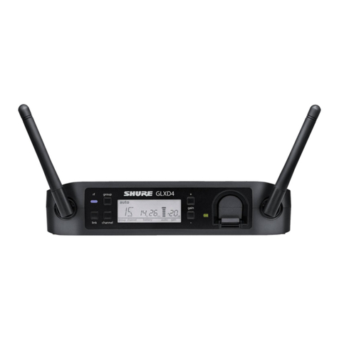
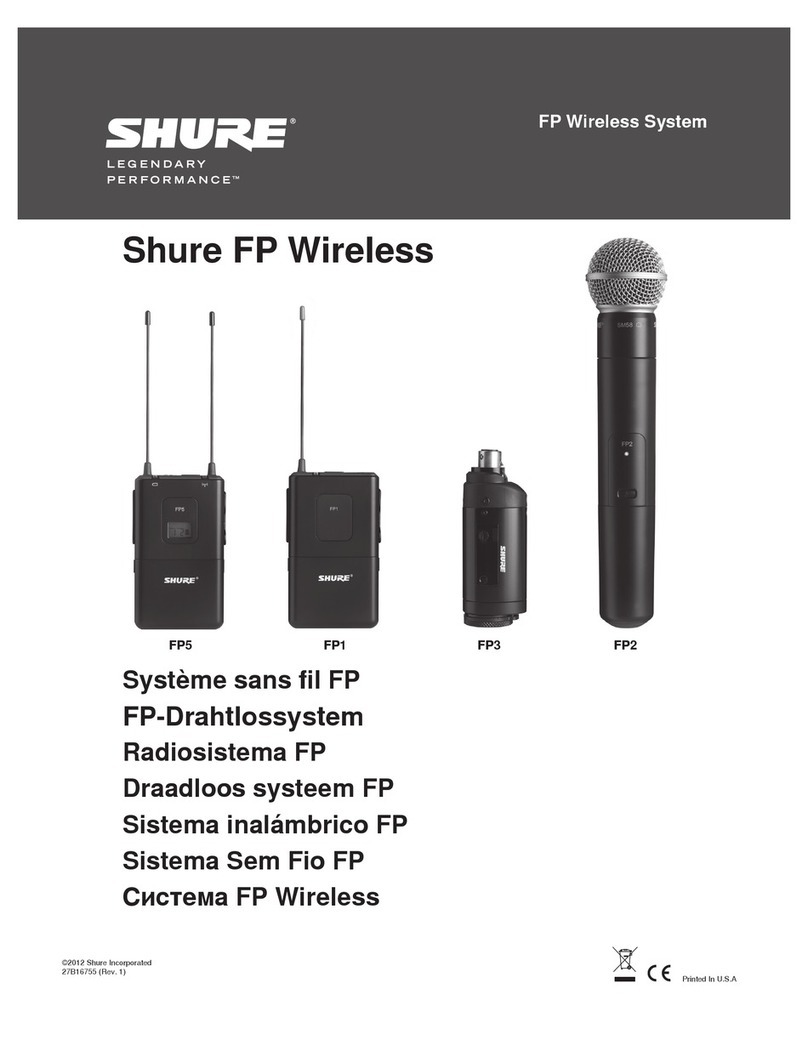
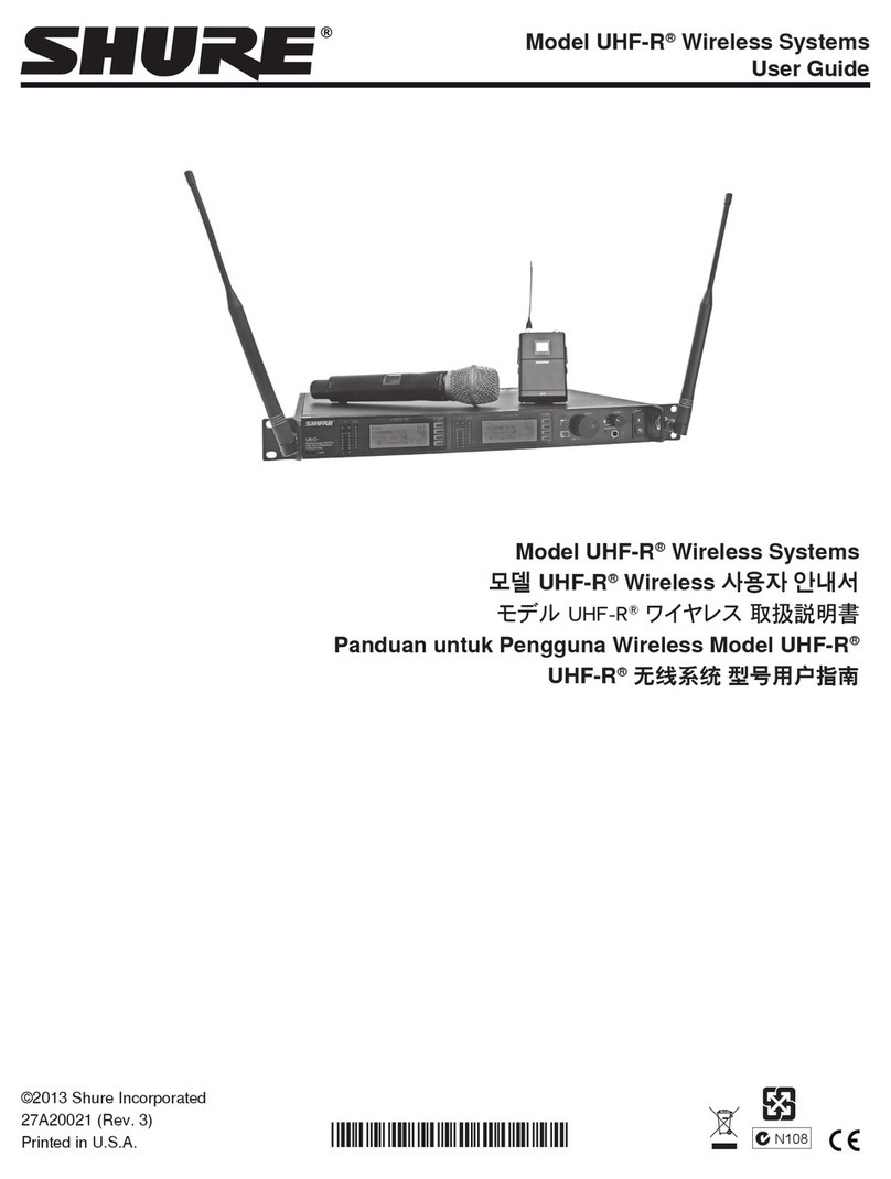
Shure GLX-D User manual

LEGENDARY
pERFORM
AN
c
ETM
(j)
GLX-D Wireless
System-
GLXD4 Receiver
fao!
c€&
© 2017 Shure Incorporated
27
A35795
(Rev
.
1)
Printed in China
11111111111111111111111111111111111111111111111111
User Gu1de
Le GUide de I
'U
I1
1isa
teur
Bed1enungsa
nl
e1
tu
ng
Ma
nu
al do Usuano
Gu1a
d
el
Usuano
Gu1d
a deii'Ut
en
te
Ge
bru1k
ershandle1
d1ng
PyK
OBOll
CT
BO
n
on
b
30s
ar
enA


Half-Rack Wireless Receiver
·-
-··
-·
------
---
...
·--
..
-
~
------~·-
··
·
·
~--
IMPORTANT
SAFETY
INSTRUCTIONS
1. READ these instructions.
2. KEEP these instructions.
3. HEED all warnings.
4. FOLLOW all instructions.
5.
DO
NOT use this apparatus near water.
6. CLEAN ONLYwith drycloth.
7.
DO
NOTblock any ventilation openings. Allow sufficient distances for adequate
ventilation and install in accordance with the manufacturer's instructions.
8.
DO
NOT install near any heat sources such
as
open flames, radiators,
heat registers, stoves,
or
other apparatus (including amplifiers) that pro-
duce heat. Do not place any open flame sources on the product.
9.
DO
NOT defeatthe safety purpose
of
the polarized
or
grounding type plug.
A polarized plug has two blades with one widerthan the other. A grounding
type plug has two blades and a third grounding prong. The wider blade or the
third prong are provided for your safety. If the provided plug does not fit into
youroutlet, consult an electrician for replacement
of
the obsolete outlet.
10. PROTECT the power cord from being walked on
or
pinched, particularly at plugs,
convenience receptacles, and the pointwhere they exit from the apparatus.
11. ONLY USE attachments/accessories specified
by
the manufacturer.
12. USE only with a cart, stand, tripod, bracket,
or
table specified by the manu-
facturer,
or
sold with the apparatus. When a cart is used, use caution when
moving the cart/apparatus combination to avoid injury from tip-over.
Explanation of Symbols
Lh
Caution: risk
of
electric shock
&
Caution: risk
of
danger (See note.)
---
Direct current
,--..,___.
Alternating current
I
On (Supply)
•
13. UNPLUG this apparatus during lightning storms
or
when unused for long periods of time.
14. REFER all servicing to qualified service personnel. Servicing is re-
quired when the apparatus has been damaged in any way, such as
power supply cord
or
plug is damaged, liquid has been spilled
or
ob-
jects have fallen into the apparatus, the apparatus has been exposed to
rain
or
moisture, does not operate normally, or has been dropped.
15.
DO
NOT
expose the apparatus to dripping and splashing. DO NOT
putobjects filled with liquids, such as vases, on the apparatus.
16. The MAINS plug or an appliance coupler shall remain readily operable.
17. The airborne noise ofthe Apparatus does not exceed 70dB (A).
18. Apparatus with CLASS I construction shall be connected to a
MAINS socket outlet with a protective earthing connection.
19. To reduce the risk offire
or
electric shock,
do
not ex-
pose this apparatus to rain or moisture.
20. Do not attempt to modify this product. Doing so could re-
sult in personal injury and/or product failure.
21. Operate this product within its specified operating temperature range.
D
Equipment protected throughout
by
DOUBLE INSULATION
or
REINFORCED INSULATION
C)
Stand-by
)?! Equipment should notbe disposed
of
in the normal waste stream
-
WARNING:
Voltages in this equipment are hazardous to life. No user-serviceable parts inside. Refer all servicing to qualified service personnel.
Th
e safety certifications
do
not apply when the operating
voltage is changed from the factory setting.
WARNING:
Battery packs shall not
be
exposed
to
excessive heat such
as
sunshine, fire,
or
the like.
WARNING:
Danger of explosion if incorrect battery replaced. Operate only with AA batteries.
WARNING:
This product contains a chemical known to the State
of
California to cause cancer and birth defects
or
other reproductive harm.
WARNING &
• Battery packs may explode
or
release toxic materials. Risk of fire
or
burns. Do not open, crush, modify, disassemble, heat above 140°F (60°C},
or
incinerate
• Follow instructions from manufacturer
Neverput batteries in mouth. If swallowed, contact your physician or local
po
ison control center
•
Do
not short circuit; maycause burns
or
catch fire
Do
not charge
or
use battery packs with otherthan specified Shure products
Dispose of battery packs properly. Check with local vendor for proper disposal of used battery p
ac
ks
Note:
• This equipment is intended to be used in professional audio applications.
EMC
conformance is based on the use of supplied and recommended cable types. The use of other cable types may degrade EMC performance.
Use this battery chargeronly with
the
Shure charging modules and battery
pa
cks for which it is designed. Use with other than the specified modules and battery packs may
increase the risk of fire
or
explosion.
Changes or modifications not expressly approved by Shure Incorporated could void your authority to operate this equipment.
Note:
Use only with the included power supply
or
a Shu
re-approved equivalen
t.

System Overview
----
···
·'
~
'
~-
.
.
..
..
GLX-D Advanced Digital Wireless Systems combine Automatic Frequency Management technology with a rack mountable metal receiver, rechargeable lithium-ion batteries,
world-renowned microphones, and unparalleled design and construction. New GLX-D Advanced Frequency Managers (available separately) connect multiple GLXD4R receiv-
er
systems for increased channel count and improved
RF
reliability, consolidating
RF
to one pair of antennas. New antenna accessories help improve reception by letting you
mount antennas closer to transmitters,' with directional reception for improved performance. Available
in
a variety
of
bodypack and handheld configurations, GLX-D Advanced
Digital Wireless sets the standard for ease of operation and digital audio clarity.
Features
Exceptional digital audio clarity
Operates in globally unlicensed 2.4 GHz spectrum
Optional GLX-D Frequency Manager allows operation
of
up
to
11
systems
New antenna accessories for remote mounting
and
improved reception
Half-rack size and metal chassis
Furnished Accessories
Reverse SMA Bulkhead Adapters, lockwasher, nut 95A32436
USB Cable, Type A to Micro-B 95A21651
0.6 m
(2ft.)
Reverse
SMA
Cable UA802-RSMA
Power Supply PS43
Shure Lithium-ion Rechargeable Battery SB902
To reduce set-up time, the transmitter and receiver automatically link to form an au-
dio channel the first time they are powered on and never have to be linked again.
Step
CD
Connect power supply to the receiver and plug cord into an AC power source.
Connect the audio output
to
an amplifier or mixer.
Rechargeable batteries deliver cost efficiency and
up
to 16 hours of runtime
• Adjustable transmitter gain to optimize audio signal
Automatically moves away from interference without audio interruption
RF back-channel for remote control of transmitter functions
Automatic transmitter power-offto conserve battery life when transmitter is not in
use
Optional Accessories
··~
.,....
-~---~-
~~~
~
-~·
.,
.~---~-~--~---~--~---~--~~~~~-----¥~~---
GLX-D Frequency Manager
Passive Directional Antenna 2.4 GHz
Reverse SMA Passive Antenna Splitter (900 MHz
ISM, DECT, 2.4 GHz)
Wall Mount for PA805Z2-RSMAand UA8-2.4GHZ
1/2 Wave Antenna, 45 deg. (2.4 GHz)
0.6 m
(2ft.)
Reverse SMA Cable
1.8 m
(6ft.)
Reverse SMA Cable
7.6 m
(25ft
.) Reverse
SMA
Cable
15.2 m (50 ft.) Reverse SMA Cable
30.4 m (100ft.) Reverse SMA Cable
Reverse SMA Bulkhead Adapters
Stand Alone Single Battery Charger
Car
Battery Charger
Step®
Install charged transmitter
batteries.
:;\!
!7
UA846Z2-LC
PA805Z2-RSMA
UA221-RSMA
UA505-RSMA
UA8-2.4GHZ
UA802-RSMA
UA806-RSMA
UA825-RSMA
UA850-RSMA
UA81
00-RSMA
95A32436
SBC10-902
SBC-CAR
.....................................................................................
.
........................................................................................
Step
@
4
Turn on the transmitter and receiver. The blue
rf
LED will flash while the
transmitter and receiver form a link. The
rf
LED turns solid blue when the link
has successfully formed.
Note:
The transmitter and receiver will remain linked for future usage. At power-
up, the blue
rf
LED and transmitter LED will illuminate, skipping the linking step.
/
..
..
-
..
....
\
'
On
)
,T.
n
u
on
on ·
=-
~
~~
c:=J
§
.
~
I
(@
'
Step@
Check the audio and adjust the gain if necessary.
SIIUiU!
GLXD
4R
®

Receiver
Controls
and
Connectors
Front
Panel
CD
RF Status LED
ON
= Linked transmitter
is
on.
Flashing = Searching
for
transmitter.
OFF=
Linked transmitter off
or
transmitter unlinked.
®
Group Button
Press and hold
for
two
seconds to
enable
manual group edit.
®
Data Sync
LED
ON
= Data sync is
on
(receiver connected
to
GLX-D
Frequency Manager).
Flashing = Searching
for
frequencies.
OFF=
Data sync is off (receiver
not
connected
to
GLX-D Frequency Manager).
0
Link Button
Press to manually link receiver to a transmitter
or
to
activate
the
remote ID
function.
®Channel
Press
to
start a channel scan.
-Press and hold for
two
seconds to enable manual channel edit.
@LCD
Screen
Displays receiver
and
transmitter status.
0
Gain Buttons
Press
to
increase
or
decrease
transmitter gain in 1
dB
increments.
Receiver Screen
CD
Group
Displays the selected
group
.
®Channel
Displays the selected channel.
®
Transmitter Battery Runtime
Displays remaining battery life in
hours
and
minutes.
Alternatively displays the following battery status:
CALC
= battery life calculation
-
Lo
=battery
life less than 15 minutes
-
Err
= replace battery
0
Audio Meter
Indicates audio signal level and peaks.
®Gain
Displays transmitter gain settings (dB).
®
OL Indicator
Indicates audio overload, reduce gain.
@
SitU~
GLXD4R
ante
nn
aS
Rear Panel
®
Battery Charging Indicator
Illuminates when battery is in charging bay:
Red=
Battery charging.
Green Flashing = Battery charge
at
90%.
Green = Battery charged.
Amber
Flashing = Charging error, repl
ace
battery.
®
Battery Charging Bay
ant
enna
A
Charges transmitter battery if receiver is plugged in
to
power outlet.
@
Power Button
Powers
the unit
on
and off.
®Antenna
Two
antennas
per
receiver. Antennas
pick
up
the signal from
the
transmitter.
®
Power Supply Jack
Connect
the supplied 15 V DC external
power
supply.
@
Firmware Update
Connect to computer to download firmware updates.
@
Mic/Line Switch
Sets XLR outp
ut
level to microphone
or
line level.
@
XLR Audio Output
Supplies microphone-level
or
line-level
audio
output.
@
lnst/Aux Out
TRS
%'' (6.35mm) audio output. Connect to mixers, recorders, and amplifiers.
cp
auto
cr
scanning
11----(D
~
(6)
I
-:3
-:38
:
+3L
I
::J
h,
C
mn :
Oda
0
Transmitter Locked
Displayed
when
linked transmitter controls are locked.
@Scanning
Indicates a scan is in progress.
®Auto
Indicates that the selected group
has
backup channels
av
ailable.
5

Transmitters
G) Antenna
Carries wireless signal.
®Status
LED
LED color and state indicate transmitter status.
®Power
Switch
Turns the transmitter on/off.
@TA4M InputJack
Connects to a 4-Pin mini connector (TA4F) microphone
or
instrument cable.
®
Micro
USB
Charging Port
Connect to USB battery charger.
@Unk
Button
Press and hold within 5 seconds ofpower-on
to
manually linkwith receiver
-Press momentarily to activate Remote ID function
(i)
BatteryCompartment
Holds
1
Shure rechargeable battery.
@ MicrophoneCartridge
GLXD-2 transmitter models are available with the following cartridge types: SM58,
Beta 58, SM86, Beta
87
A.
Transmitter Status LED
LED is green during normal operation.
LED color
or
flashing indicates a change in transmitter status as shown in the follow-
ing table:
Color State Status
Green Flashing (slow) transmitter attempting relink with
receiver
Flashing (fast) unlinked transmitter searching for
receiver
Flashes 3 times indicates locked transmitter when
power switch is pressed
Red On battery life < 1 hour
Flashing battery
life<
30 minutes
Red/Green Flashing remote
10
active
Amber Flashing battery error, replace battery
Wearing the Bodypack Transmitter
Clip the transmitterto a belt
or
slide a guitarstrapthrough the transmitter clip
as
shown.
Forbest results, the belt should
be
pressed against the base
of
the clip.
6
l
~
~
•
WI
[.7
Wearing the Headworn Microphone
Position the headworn microphone 13 mm (1/2 in.) from the corner of your mouth.
• Position lavalier and headworn microphones so that clothing, jewelry,
or
other
items
do
not bump or rub against the microphone.
Correct Microphone Placement
Hold the microphone within 12 inches
fro~
the sound source.
For a warmer sound with increased bass presence, move the microphone closer to
the sound source.
Do
not
cover grille with hand.

-
--
----
--
Batteries and Charging
GLX-D transmitters are powered byShure SB902 lithium-ion rechargeable batteries. Advanced battery chemistry maximizes runtimes with zero memory effects, eliminating
the need to discharge batteries prior to charging.
When not in use, recommended battery storage temperature
is
10oc
(50°F) to
25°C
(77°F).
Note:
The transmitter will not pass RF
or
audio signals when connected to the charging cable.
The following battery charging options are available:
Receiver Charging Bay Charging from an AC Power
Source Charging from a USB Port
1. Plug the USB charging cable into the
charging port on the transmitter.
The receiver's built-in charging bay will charge trans-
mitter batteries when receiveris plugged in to power
outlet.
1. Insertthe battery into the charging bay.
2.
Monitor the battery charging indi-
cator on the front panel.
LED
Status During Charging
1.
Plug the charging cable into the charg-
ing port on the transmitter.
2. Plug the charging cable into an AC power source.
2.
Plug the cable into a standard USB port.
The following LED states indicate battery status when the transmitter is connected
to
a
charger:
Charging Times and Transmitter
Runtimes
Green
=
charging complete
Green Flashing
=
battery charge
>
90%
Red
=
battery charging
Amber Flashing
=
battery error, replace battery
Installing Transmitter
Batteries
Bodypack Transmitter
1.
Move the locking lever to the open posi-
tion and slide the battery dooropen.
2. Place the battery into the transmitter.
3. Close the battery door and slide the latch to lock.
Handheld Transmitter
1. Unscrew and remove the battery cover.
2. Place the battery into the transmitter.
3. Replace and tighten the battery cover.
0
Use the following table
to
determine approximate battery runtime based on
the duration
of
charging time. Times shown are in hours and minutes. GLX-D
transmitters automatically power-off after approximately 1 hourto conserve
battery life if the signal from a linked receiver is not detected.
Receiver Bay or USB Transmitter Runtime
AC Power Source Connection
Charging Charging
0:15 0:30 up to 1:30
0:30 1:00 up to 3:00
1:00 2:00 up to 6:00
3:00 4:00 up to 16:00*
*Storage time orexcessive heat will reduce maximum runtime.
Note:
Ifreceiver is powered off and remains plugged in, batterywill continue
charging.
Important Tips for Care and Storage
of Shure Rechargeable Batteries
Proper care and storage ofShure batteries results in reliable performance and
ensures a long lifetime.
• Always store batteries and transmitters at room temperature
Ideally, batteries should
be
charged
to
approximately 40% ofcapacity for
long-term storage
During storage, checkbatteri
es
every 6 months and recharge to 40%
of
capacity as needed
7

Remote Antenna Placement
--
~--
-~
-..-"·
-
---~-
---~---~···
~-----~---
-
-~
~~
~
·
·
·~---
·~·----
Follow these guidelines when mounting antennas remotely:
Reduce distance between transmitter and antenna.
Mount antennas farther from each'other
to
improve performance.
Position antennas so there is nothing obstructing the line of sight to the transmitter, including the audience.
Keep antennas away from metal objects and any other antennas.
Use only low-loss reverse SMAcable to avoid poor RF signal.
-Consult cable's specifications and calculate signal loss for desired cable run.
Use one continuous length of cable from the antenna
to
the receiver to increase signal reliability.
Always perform a walk-around test to verify coverage before using a wireless system during a speech or performance. Experimentwith antenna placement to find the opti-
mum location. If necessary, mark any trouble spots and ask presenters
or
performers to avoid those areas.
Multiple Receiver Systems
To run more than two receivers at the same time, the GLX-D Frequency Manager is recommended to improve RF reliability.
However, you can run multiple receivers without the frequency manager. Select the group by determining the total number of receivers in your system (channel count). All
receivers in the system must be set to the same group.
Group Channel Count Number
of
Backup Notes
(Number
of
Receivers) Frequencies Per Channel
1 Up to 4 3 Initial factory setting.
2
Up to 5* 3 Best
multi-channel
group if you experience interference.
3 Up to 8*
0
Only use Group 3 in controlled Wi-Fi environments because there are no backup
frequencies to avoid interference.
4 1
27
Best
single-channel
group if you experience interference.
*Environmentally dependent, 4 systems typical
See "Tips to Improve Wireless System Performance" section for additional information. For information about receiver groups when connected to the GLX-D Frequency
Manager, see the UA846 user guide.
Setting Up Receivers and Transmitters
Note:
Before beginning, turn off all receivers and transmitters. Turn on and set up
'each receiver/transmitter pair individually to prevent cross-linking.
1. Turn
on
the first receiver.
2. Press and hold the
group
button to select a group (if necessary) or if the group
is already set, press the
channel
button to scan for the best available channel.
group channel
:.{;
.,
.
....
.
3. Turn
on
the first transmitter. The
rf
LED turns sol-
id blue when a link is established.
Repeat steps 1-3 for each additional receiver and transmitter. Remember to seteach
receiver to the same group.
Note:
Dashes appearing on the group a·nd channe!tdisplay
during a channel scan indicate that frequencies are not avail-
able in the selected group. Choose a group that supports
more receivers and repeat set-up steps.
See GLX-D Frequency Manager guide for setting up receivers and transmitters when
connected to the frequency manager.
--.-
~-
~
-
--
--
-
-
-
~------------
--~--
-
-
...
-~·-··
·
-·-
·
--~
....
.,....---
-
-~-
-
~
--
-
--
---
..
~-.
Manually Linking a Transmitter to a Receiver
-
~
-
~-
~---
·
--
·------
-
--
-·
-w-~
·-·~
-·-
~·~•-
---.----
·
-
.
~--·-··---~
--~
-
~
-~·
-
~
-~.
--·-
..
-·•-••••
-
___
,
...
___
~
-
-
-----~-
·
-·--.-
----
-
-------
-
--~
-
--
·
·· ·
···
Use the manual linking option to change the transmitter linked to a receiver. A common use for manual linking is changing the linked transmitter from a bodypack type to a
handheld type.
1. Turn on the transmitter: Within 5 seconds, press and hold the
LINK
button until the transmitter LED begins to flash green.
2. Press and hold the link button on the receiver: The blue
rf
LED will flash, and then remain on when the link has been established.
3. Test the audio to verify the link and adjust the
ga
in if necessary.
- -
------·-·---
--
---
--
..
-·--·
-·--·-
--·--
-
----·-
--
-
.............
_,
__
___
_
___
_
____
,
,,
,
.........
.....
......
..
......
_____
___
,
..
......
...
....
..
..
..
..
.....
.
..
...
-
...
..
..
..
...
...........
..
.......
......
..
......
.....
.
....
--
-- -
----
..
-
·-
--
-
-·----
Combo Systems
A combo system is created by linking two transmitters to a single receiver. Only one transmitter can be active at a time to prevent cross interference.
Ga
in settings for each
transmitter can be independently set and stored when the transmitter is active.
Important!
Do notturn on and operate both linked
tr
ansmitters at any time.
Turn off both transmitters before beginning.
1. Press the
group
button to select a group. The receiver automatically scans the selected group to find the best available channel.
2. Turn on transmitter 1 and link itto the receiver. Adjust the gain, and then turn off the transmitter.
3. Turn on transmitter 2 and link itto the receiver. Adjust the gain, and then turn off the transmitter.
Note:
A
tr
ansmitter can only link to one GLX-D receiver at a time.
8

2.4
GHz
Spectrum
Overview
--
-~-
·
·
·
··
·
--·
··
··
-•
" ""
·
~·
·
··
··
·"'""
"
~·
--·
··
·
~·
~
-~
-
~
..~
..
..
......
..
-·~-
·
-
-
·
"'
"
"
'~
··
··~
·".
GLX-D operates within the 2.4GHz ISM band which is utilized by Wi-Fi, Bluetooth, and other wireless devices. The benefit of 2.4GHz is that it's a global band that can
be
used
anywhere in the world, license free.
Overcoming
the
Challenges
of 2.4 GHz
The challenge of 2.4 GHz is that Wi-Fi traffic can be
unpredictable. GLX-D meets these challenges
in
the
following ways:
Coexisting with Wi-Fi Challenging Wireless
Environments
Some environments are more difficult than others for 2.4 GHz
wireless system performance. Additionall
y,
body absorption
has a greater impact in the 2.4 GHz spectrum compared to
the UHF spectrum. The simplest solution
in
many cases is to
reduce transmitter-to-receiver distance by placing receivers
• Prioritizes and transmits on the best three frequen-
cies perchannel (choosing from a pool of six fre-
quencies across the 2.4 GHz band)
Seamlessly moves away from interference to back-
up
frequencies without audio interruption
If you plan to use Wi-Fi during a perfor-
mance, turn on Wi-Fi devices prior to turning
on GLX-D and scanning for the best chan-
nel. GLX-D detects and avoids other Wi-Fi
traffic
by
scanning the entire 2.4 GHz en-
vironment and selecting the three best fre-
quencies to transmit on. This method avoids
Wi-Fi signals and results in reliable perfor-
mance for your GLX-D wireless system. on the stage with a clear line
of
sight. You can also mount
antennas remotely using Shure directional antennas to reduce
transmitter-to-antenna distance.
Optional GLX-D Frequency Manager improves RF
reliability for systems with more than two receivers
• Continuously scans during usage to rank all fre-
quencies (both current and backup frequencies)
"Bursting" Wi-Fi is harder to detect as it is
periodic; however, because GLX-D only re-
peats the most important information, even
bursts at very high levels don't have an ef-
fect on your audio performance.
Challenging environments include:
Areas with few reflective surfaces such as:
-Outdoors
-Buildings with very high ceilings
• Antenna mounting accessories and directional
antennas (available separately) help reduce trans-
mitter-to-antenna distance and connect to antenna
splitter
Three or more GLXD4R receivers in use and not connected
to a GLX-D Frequency Manager
Areas with a strong Wi-Fi presence
2.4 GHz systems from other manufacturers in use
Note: Unlike analog TV band wireless system which typically use the same type of transmissions across manufacturers, all 2.4 GHz wireless currently on the market use dif-
ferent variations of wireless transmission. These differences make it more difficult to mix and match 2.4 GHz systems from multiple manufacturers, as can bedone with
TV
band wireless solutions.
Tips
to
Improve
Wireless
System
Performance
--
-~-
-
--
~
·
O
"H
-
·
0
0'
' " ' •O
••
P · · ·
o-
-O
o0
'·0
0'
' • - < • U
hOO'-
- · -
or>-
0
0--
0 0 0' '
0'0
0
''"
'
·'-•
''
0 .
,,
·~
··
-··-
--
-
0 - ·
-
~---
'-'·
'
'
·'
•
·
-~'
-·
'·
·
0
.,
"
·'
' 4
,,
. ,
,_,
..
, 0
·•·-
. , ' • '
•>
-------
'-'-'••
'>
0 . ,
If you encounter interference
or
dropouts, try the following suggestions:
1.
Place receiver
atleast3
meters
(1
0 feet) away from Wi-Fi ac-
cess points, computers,
or
other active 2.4 GHz sources.
Avoid heavy Wi-Fi traffic activities such as downloading large files
or
viewing a
movie.
Turn on any Wi-Fi prior to turning on GLX-D and scanning for the best channel.
2. Reduce transmitter-to-receiver distance by placing receivers on stage
or
above the audience with a clear line of sight to the transmitter.
Move receiver to the top of the equipment rack for a clear line of sight.
Mount antennas remotely to place closer to transmitters and improve RF reli·
ability if receivers cannot
be
moved closer.
Make sure people
do
not block the line
of
sight between receiver and
transmitter.
Additional Tips
• Do not place competitive 2.4 GHz receivers near GLXD4R receivers.
• Connect more than two GLXD4R receivers to a GLX-D Frequency Manager
to improve
RF
reliability.
• Scan for the best available channel by pressing the
ch
annel button.
• Keep transmitters more than 2 meters (6 feet) apart. This is less critical with
shorter receiver-to-transmitter distances or if receivers are connected to a
GLX-D Frequency Manager.
Note: If transmitters are within 6 inches
of
non-GLX-D transmitters
or
micro-
phone cartridges, audible noise is possible.
• Move transmitter and receiver away from metal or other dense materials.
• During sound check, mark trouble spots and ask performers
to
avoid those
areas.
• If there is a strong source
of
Wi-Fi and you specifically want to use frequen-
cies within that Wi-
Fi
channel, use the following Group/Channel combina-
tions (best option listed first):
Wi-Fi
1:
Group 3/Channel 8, Group 3/Channel 4
Wi-Fi 6: Group 3/Channel
7,
Group 3/Channel 5
Wi-Fi 11: Group 3/Channel
2,
Group 3/Channel 1
J (!)
~
~
'.Jti"
...
..
-
-
---
-
- -
-
-
- -
- -
-
---
-
-
~J.
J
~
0
-:::=::c
f
~'"~
/
~
-
9
Operation
-
--
Gain Adjustment
Usethe gain buttons on the receiver to increase
or
decrease the gain of a linked
transmitter:
• Turn on the linked transmitter and momentarily press the gain buttons to adjust
the gain in 1
dB
increments
• For faster gain adjustments, press and hold the gain buttons
•
To
replicate the output level of a guitar, unity gain is -18
dB
for the
V."
output
Tip:
Monitor theaudio and observe the receiver audio meter level while adjusting
the gain to prevent signal overload.
Locking and Unlocking the Controls
The controls of the receiver and transmitter can
be
locked to prevent accidental or
unauthorized changes to settings.
Note:
Locks are not affected by powercycles.
Locking the Receiver Controls
Simultaneously press and hold the group and channel buttons until
LK
appears on
the LCD. Repeat to unlock.
•
LK
is displayed ifa locked control is pressed
•
UN
is displayed momentarily
to
confirm the unlock command
SHU~
GLXD4R
rf
group
':
0,---------,
DO
link c
hanne
l
'--
------..J
Locking the Transmitter Power Switch
®
Starting with the transmitter set
to
off,
press and hold the LINK button while turning
on the transmitter. Continue to hold the linkbutton until the lock icon appears on the
receiver LCD. Repeat sequence to unlock.
i
Optionally, the transmitter power switch can be remotely locked from the receiver
front panel:
Simultaneously press and hold the
group
and
link
buttons for approximately 2
seconds until the flashing lock icon appears on the receiver LCD. Repeat sequence
to
unlock.
Identifying Linked Transmitters and Receivers with Remote ID
Use the Remote ID feature to identify linked transmitter and receiver pairs
in
multiple receiver systems. When Remote ID is active, the receiver LCD will blink and display ID.
The
status LED of the corresponding transmitterwill alternately flash red and green for approximately 45 seconds.
To
activate Remote ID:
1. Momentarily press the
link
button on the transmitter or receiver.
2. The LCD ofthe linked receiver will blink and display ID and the status LED on the linked transmitter will flash red/green.
3. To exit Remote ID mode, momentarily press the
link
button or allow the function to timeout.
.....
-·
Manually Selecting a Group and Channel
Specific groups and channels can
be
assigned to the receiver instead
of
using the automatic scan function.
Note:
Group 3 should only be used in controlled Wi-Fi environments to preventinterference from unexpected Wi-
Fi
devices.
Selecting a Group
1. Press and hold the
group
button for 2 seconds until the
group
display flashes.
2. Press the
group
button to scroll through the available groups.
3. The receiver will automatically save the selected group.
Selecting a Channel
1. Press and hold the
channel
button for 2 seconds until the
channel
display flashes.
2. Press the
channel
button to scroll through the available channels.
3. The receiver will automatically save the selected channel.
.1:
>
1ii
''
i
Note:
A double dash
symbol--
displayed
on
the receiver screen during a channel scan indicates that there are no available channels within the selected group. Choose a
groupwith more channels and repeat set up steps.
10

Firmware .
'
Firmware is embedded software in each component that controls functionality. Periodically, new versions offirmware are developed
to
incorporate additional featuresand
en-
hancements.
To
take advantage ofdesign improvements, new versions of the firmware can be downloaded and installed using the Shure Update Utilitytool.
Software is available for download from
http:/
/www
.shure.com/update-utility.
Connect to the Computer
Connect thedevice to your computer using the USB to Micro USB cable supplied with your GLX-D system.
GLXD4R
m-
~
' ,
GLXD1
GLXD2 • '
17
Rack-Mounting Instructions
Use the supplied mounting hardware to install the receiver in a standard 19 inch audio equipment rack.
/ wll
.,.
.
~
·
.
-C
l
.,.
-
~-·
Resetting Components
'
------------------------------------------------
Use the reset function if it is necessary
to
restore
the
transmitter or receiverto theirfactory settings.
Resetting the Receiver
Restores the receiver
to
the following factory settings:
• Gain level = default
• Controls
=
unlocked
Press and hold the
link
button while turning on the receiver power until the LCD displays
RE.
Note:
When reset
is
complete, the receiver will automatically initiate linking to search for a transmitter. Press and hold the transmitter link button within five seconds
of
power-
ing-on to complete the link.
Resetting the Transmitter
Restores the transmitter
to
the following factory settings:
• Controls
=
unlocked
Press and hold the transmitter linkbutton while turning
on
the transmitter until power LED goes off.
When the link button is released, the transmitter will automatically initiate linking
to
find an available receiver. Press the linkbutton on an available receiver to relink.
11

Troubleshooting
Issue Indicator Status Solution
No sound or faint sound Receiver
RF
LED on • Verify all sound system connections or adjust gain
as
needed (see Adjusting
Gain).
• Verify that the receiver is connected to mixer/amplifier.
Receiver
RF
LED off • Turn on transmitter.
• Make sure the batteries are installed correctly.
• Link transmitter and receiver (see Linking section).
• Charge
or
change transmitter battery.
Receiver LCD screen • Make sure AC adapter is securely plugged into electrical outlet.
off • Make sure receiver is powered on.
Transmitter indicator Charge
or
change transmitter battery.
LED flashing red
Transmitter plugged Disconnect transmitter from charger.
into charger.
Audio artifacts
or
dropouts
RF
LED flickering • Change receiver and transmitter to a different group and/or channel.
or off • Identify nearby sources of interference (cell phones, Wi-Fi access points,
signal processor, etc.) and shut down
or
remove source.
• Charge or change transmitter battery.
• Ensure that receiver and transmitter are positioned within system
parameters.
• System must be set up within recommended range and receiver kept away
from metallic surfaces.
• Transmitter must be used
in
line of sight from receiver for optimal sound.
Distortion OL indicator appears Reduce transmitter gain (see Gain Adjustment).
on receiver LCD
Transmitter and receiver link unsuccessful Transmitter and re- Update both components to firmware version 2.0 or greater. Download the
ceiver LEOs flash to Shure Update Utility application and follow the instructions.
indicate that linking
started, but the link
fails
Sound level variations when switching to dif- N/A Adjust transmitter gain as necessary (see Gain Adjustment).
ferent sources
Receiver/transmitter won't turn
off
Transmitter LED Controls locked. See Locking and Unlocking Controls.
flashing rapidly
I
Receiver gain control cannot be adjusted N/A Check transmitter. Transmitter must be on to enable gain changes.
Receiver controls cannot be adjusted
LK
shown on receiver Controls locked. See Locking and
Uni9C~ing
,
Controis. ·
·
:,;
·
I
display when buttons
.
.
.
are pressed
Transmitter ID function does not respond Transmitter LED Controls locked. See Locking and Unlocking Controls.
I
flashes green three
times
I
Transmitter information does not appear on N/A Linked transmitter is off or the receiver is not linked to a transmitter.
I
the
Receiver LCD
I
Transmitter powers off after one hour Transmitter status GLX-D transmitters automatically turn off after one hourto conserve battery I
LED off life if the signal from a linked receiver is not detected. Make sure that linked
receiver is turned on.
I
Second frequency manager does not send Data sync LED off Verify that
antenna
Aand
antenna
Bports on second frequency manager are
I
RF signal
to
receivers connected to cascadeA and cascadeS ports on first frequency manager.
RF interference while connected
to
Ire- Receiver screen Move system away from other 2.4 GHz sources such as Wi-Fi access points
quency manager flashes - -
--
or computers. If using directional antennas, place interference sources behind
antennas in the null
to
minimize interference. Place receivers ordirectional
antennas closer to transmitters.
12

Specifications
-
--·--'""
"
"""''"~·
·
·
~
··~~
•·•·
•
•·~"""
"··"••·
,,
~
•
-.
-
••
-·~~~
-
·
~
·
·
•~~
·
·"'
'
•
~•
•••~
•
~·
·
-
~
••
•w
Tuning
Bandwidth
2400-2483.5 MHz
Working
Range
Up
to 30 m (100ft) typical, Up to 60 m (200 ft) maximum
Up to
20m
(65ft) typical, Up to 50 m (165ft) maximum
Note: Actual range depends on RF signal absorption, reflection and interference.
Transmit
Mode
Shure GLX-D proprietary digital
Audio
Frequency Response
20Hz-20kHz
Note: Dependent on microphone type
Dynamic
Range
t 20 dB, A-weighted
RF
Sensitivity
-88 dBm, typical
Total
Harmonic
Distortion
0.2%, typical
RF
Output
Power
10
mW E.I.R.P. max
Operating Temperature Range
-18°C (0°F) to
57"C
(t35°F)
Note: Battery characteristics may limit this range.
Storage
Temperature Range
-29°C
(-20°F) to
74°C
(165°
F)
Polarity
Positive pressure
on
microphone diaphragm (or positive voltage applied to tip of WA302 phone
plug) produces positive voltage on pin 2 (with respect to pin 3
of
low-impedance output) and the
tip of the high impedance 1/4-inch outpu
t.
Battery
Life
Up
to 16 hours
Channel
Count
Up to 11 maximum
GLXD1
Dimensions
90 x 65 x 23 mm(3.56 x 2.54 x 0.90in.), Hx W x D (without antenna)
Power
Requirements
3.7 V Rechargeable
Li
-lon
Housing
Cast Metal, Black Powdercoat
Input
Impedance
9001<0
RF
Output
Power
10
mW E.I.R
.P
. max
Transmitter Input
Connector
4-Pin male mini
co
nnector (TA4M)
Configuration
Unbalanced
Maximum
Input
Level
1 kHz at 1%
THD
+8.4 dBV (7.5 Vp-p)
Antenna
Type
Internal Monopole
Pin Assignments
TA4M
1 ground (cable shield)
2 + 5 V Bias
3 audio
4 Tied through active load 1
to ground (On instrument I
adapter cable, pin 4 floats)
T
A4M
Connector
5V
DC
Audio
In
put
Ground
GLXD2
B
ft]
]
lr
~
J=JI
c
Dimensions
Model A B
SM58
51
mm, (2.0
in
.) 252 mm, (9.9 in.)
BETA 58
51
mm, (2.0 in.) 252 mm, (9.9 in.)
SM86 49 mm, (1.9 in.) 252 mm, (9.9 in.)
BETA
87A
51
mm, (2.0 in.) 252 mm, (9.9 in.)
-
Weight
SM58 267 g (9.4 oz.) without batteries
BETA
58
2
21
g (7.8 oz
.)
without batteries
SM86 275 g
(9
.1
oz.) without batteries
BETA 87A 264 g (9.3 oz.) without batteries
Housing
Molded Plastic
Power Requirements
3.7 V Rechargeable
Li
-lon
RF
Output
Power
10 mW E.I.R.P. max
Maximum
Input
Level
SM58 146 dB SPL
BETA 58 147 dB
SP
L
SM86 143
dB
SP
L
BETA 87A 147
dB
SPL
GLXD4R
Dimensions
42 X 197 X
t63
mm
(1
.7 X 7.8 X 6.4 in.), H X W X D
Weight
907.2 g (32 oz.) without batteries
Housing
steel
Power
Requirements
14 to 18 V
DC
(Tip posit
iv
e with respect to ring), 550
rnA
Spurious
Rejection
>35 dB, typical
Gain
Adjustment
Range
-1
8 to 42 dB
in
1 dB steps
Phantom Power Protection
Yes
c
37 mm,
(1
.5 in.)
37 mm, (1.5 in.)
37 mm, (1.5 in.)
37 mm, (1.5 in
.)
13

Audio Output
Configuration
XLR Output
I
Ba)anced
6.35
mm
(1/4") output
I
Impedance balanced
Impedance
XLR Output I 1
00
Q
6.35
mm
(1/4") output
I
100
Q
(50
0,
Unbalanced)
Full
Scale
Output
1/4" (6.35
mm)
I +12 dBV
XLR I LINE setting= +18 dBV, MIG setting= -12 dBV
Mlc/Une Switch
30 dB pad
Pin
Assignments
XLR Output 1=ground, 2=hot, 3=cold
6.35 mm (1/4") connector Tip=audio, Ring=no audio, Sleeve=ground
Receiver Antenna Input
Impedance
500
Antenna
Type
'12
Wave Sleeve Dipole
Maximum
Input
Level
-20dBm
Receiver Output Connectors
47~-J
F
r-v
prl
instrumenU aux
~
mic/line
--
--
-
-
-·---
--~---·
··
··
·
------·--
·
--
Certifications
This device complies with part
15
ofthe FCC Rules. Operation is subject to the fol-
lowing two conditions: (1) This device may not cause harmful interference, and (2)
this device must accept any interference received, including interference that may
cause undesired operation.
This wireless system operates in the globally available ISM band 2400 MHz to
2483.5 MHz. The operation does not require a userlicense.
Certified by
IC
in Canada under RSS-247 and ASS-GEN.
IC: 616A-GLXD1, 616A-GLXD2, 616A-GLXD4RZ2
Certified under FCC Part 15.
FCCID:DD4GLXD1,DD4GLXD2,DD4GLXD4RZ2
Industry
Canada ICE5-003
Compliance
Label: CAN ICES-3 (B)/NMB-3(8)
This device complies with Industry Canada licence-exempt ASS standard(s).
Operation ofthis device is subject
to
the following two conditions: (1) this device may
notcause interference, and (2) thisdevice must accept any interference, including
interferencethat may cause undesired operation ofthe device.
Le present appareil est conforme aux CNR d'lndustrie Canada applicables aux ap-
pareils radio exempts de licence. L'exploitation est autorisee aux deux conditions
suivantes : (1) l'appareil ne doit pas produire
de
brouillage, et (2) l'utilisateur de
l'appareil doit acceptertout brouillage
radiOE!Iectrique
subi, meme
si
le brouillage est
susceptible d'en compromettre le fonctionnement.
14
Meets essential requirements of the following European Directives:
WEEE
Directiv~
2002/96/EC, as amended by 2008/34/
EC
• RoHS Directive 2011/65/EU
Note: Please follow your regional recycling scheme for batteries and electronic
waste
Hereby, Shure Incorporated declares that the radio equipment is in compliance with
Directive 2014/53/EU. The full text of the EU declaration of conformity
is
available at
the following internet address: http:
//
www.shure.com/europe/compliance
Authorized European representative:
Shure Europe GmbH
Headquarters Europe, Middle East
&
Africa
Department: EMEA Approval
Jakob-Dieffenbacher-Str. 12
75031 Eppingen, Germany
Phone: +49-7262-92 49 0
Fax: +49-7262-92 49
11
4
Email: [email protected]
Information to the user
This equipment has been tested and found to comply with the limits for a Class B
digital device, pursuant to Part 15ofthe FCC Rules. These limits are designed to
provide reasonable protection against harmful interference in a residential installa-
tion. This equipment generates uses and can radiate radio frequency energy and,
if not installed and used
in
accordance with the instructions, may cause harmful
interference
to
radio communications. However, there is no guarantee that interfer-
ence will not occur in a particular installation.
If
this equipment does cause harmful
interference
to
radio or television reception, which can
be
determined by turning the
equipment off and on, the user is encouraged to try to correct the interference by one
or
more of the following measures:
Reorient or relocate the receiving antenna.
Increase the separation between the equipment and the receiver.
Connect the equipment to an outlet on a circuit different from that to which the
receiver is connected.
Consult the dealer
or
an
experienced radio/TV technician f
or
help.
~If!(;:~
L.,
1:0))1~
.::O)!~U§O)fflfl~
i
.Ji~i'f't'li
.
t-Tv/:/~0)~~
·
~~
·
~l'ftlfi!IHO)IitJ>I:li
0)~~7-1'
::..-~'t'fflfl~tt.n,.Q31Jl'f*r-l.il1JJfiO)tJti*J1!«~,Fqj
(~!if-!-~9.Q1!«~
,Fqi)
&U:~;j~'J''II.tJ1!«~,Fqj
(~~-!-~Gf.J:~I1!«~,Fqj)
~U:I:7x7.:~.71!«~,Fqj
(~
~-!-~9.Q1!«~,Fqj)
tJ
!
J.IIfl~tt.n'*'t,
1
.::O)Jift-!-itlfl't.QJliir;:,
m<'t'311!
i*~.il~lfiO)mi*J1l«~,Fqi&U:~~'J'Ii.tJ1!«~,Fqi~U:I:7x>
7
.:~.
71l«~,FqitJ!illfl
~tl.
<:WJ:~I.::ct-!-li!ll~lgt..,<:l'~~~,
2
)j-,
.::O)$iM.'b311li*r.l.iJ
I
JJfiO)mi*J1!«~,Fqi
(;::t-J'
G
<::f;ll§f.J:'IIi.Ji'fil!i0)$1JI];IJ!~$
L-t.::~~(;:
11,
.
ia!~tJ>(;:iflfl~iJi~Hl:
:i!!'t.QtJ>J(IitiJiO)~~-!-~.I!:L-t.::..t
,
Hcillil!~l;:~iJO~.
il
mJllliefO)t.::
.lf)0)5ll!,JI:~
(iJ
IJ;;t!;f,
/~-7-{
Y 3
/O)~JI:f,;:c')
(;:?~II:
.::::"~ti1!JI:l'~
P,
3
~0)-ft!!,
;:O)jlftfJ'b31:1Ji.$~,illjJfiO)~;j~lj\fgjJ1ft{~~if';.Q~
1(;1:7X"T
.:L
71ft{~,Fqj
r::Mt-
<::t;Jl§t,;:t
i
.li'filli0)$0'1tJ!~~
t-t.::l:i~t,;:ciiiJtJ'sil
~J
0).::
c!J!R~
t.::c
~
11.
i*M
e
r:~ti;O)l!.&~i-\:
Ilh!i*t.::I111.14J\r.!i"-Sro%
~~btt<
t
::!.
~
~
,,
1-\:I.Ir.!is
J:
U:JIIB'Er.!immr;~:
Shure
B
l.$:~g?
I
:1'!1'4
t-
http://www.shure.co.jp
<:'b.::::~~'
t.::t::!.lt£9
,
m.ll.~ff-ac-lS-r:?~
'<:
12.4
XX
81
!.ll..ll.~ff-~c-lS-11,
~:.ll'O).::c-!-~t-n'*'t
,
.::0)1!«~!1HI1
2.4GHz '1!fO)!IiJi
-!-
fflfl
!,-,
~N!l1iitl1
r
~O)it!!J
O):tiit
,
ti!~
~
'fillillll:ltiUOm
't''t,
2,400MHz -
2,483.5MHz O):i:il!fb£-!-itJ!l [.,,
31JJi*~
.iJ
IJ~
JI
O)il!f!t-!-Jlllief't
.Q.::
eli<.'~
*it
lv,

SHURE®
LEGENDARY
PERFORMANCE'"
United
States, Canada,
LatinAmerica, Caribbean:
Shure Incorporated
5800WestTouhy
Avenue
Niles,
IL
60714-4608 USA
Phone:+
1847-600-2000
Fax
:+1847-600-1212(USA)
Fax:+1 847-600-6446
Email:
info
@s
hur
e
.com
www
.s
hure.com
Europe,
Middle
Eas
t, Africa:
Shure E
urope
GmbH
Jakob-Dieffenbacher-Str. 12,
75031 Eppingen,Germany
Phone:+
49
-7262-92490
Fax:
+49-7262-92491
14
Email:
info
@shure.de
www
.shure.eu
As
ia
, Pacific:
Shure Asia Limited
22/F, 625 King's Road
North
Point, Island
East
Hong
Kong
Phone: +852-2893-4290
Fax
:+852-2893-4055
Email: info@shure.com.hk
www
.shureasia.com

SHUiQ:
C€&)tB3
-
Printed
in
China
0 2017 Shure Incorporated
27A32198 (Rev. 2)
A Firmware Update May
be
Required
Shure
periocUcally
updates
device
firmware
to
add
features
and
improve
system
per-
formance. All
devices
in
you
r
system
must
operate
the
same
firmware
version
for
full
functionality. Ifyour system is not functioning
propeMy,
use
the Shure Update Utility applica-
tion
to
obtain
the
latest
devicefirmware.
Download
the
apphcation from
the
Shure
website
(http://www.ahure.com/update-utility)
and
update
devices
to
firmware
version
2.0
or
greater.
H
you
require further assistance
please
search
our
FAQdatabase (http://shure.custhelp.com)
or
contactyour local Shureservicecenter.
Une
mise
iljour
du
firmware
peul
itre
demand8e
Shure
met
r6guli6rement8
jour
le
firmware
de
l'appareil
pou
r ajouter
des
fonctions
et
am81iorer
les perfonnances
du
systeme.
Pourpouvoir
ut
ilisertoutes lesfonctions
disponill'es
,
Ia
mArneversion
de
firmware
do
it
Atre instal
lee
su
r t
ousles
appareils
du
sys-
tEtme.
Si
)e
systt\me
ne
fonctionne
pas
bien,
utilise~
!'applicati
on
Shure Update Utility
pou
r
obtenir
le
demier
fi
nnware
dispon!ble.
T
~Siecharger
I'application
depuis
le
site
web
de
Shure
(http
:/
fwww
.sh
ure
.com/update-uti!ity)
et
mettre
kJs
appareils A
jour
en installant
le
firmware
version
2.0
ou
utterieure.
Pour
obtenV'
de
I'aide, consulter
notre
base
de
donnees FAO (http://shure.custhelp.com)
ou
contacte
r
le
centre
de
r!Sparations
Shure
ti
proximit~.
MoJKeT
ncrrpe6oan.c:R
o6HOIUI8HIIe
Er
kan eenflrmware-update
nodig
IIHIIponporpaiiiiW
zljn
K.oMnaHMA
Shure
nepMCWNSCKM
o6HOBI1ReT
_..,.._
)ICYpOiiclaa
c-
l1068B11eHMR HOBbiX
~YHKI.lMM
H
yn)'\{W&HHA
pa6otw
CMCT8Mb1.
~A
o6ec~e
H
MA
....-
'""KUMOH811bHOCTM
ace
ycTpCllicTaa
•
--
110-
pa6cmm.
H8
TOil""'
-~.£cmoCMCr8Ma
...
pa6oTMT-
o6paoou,
~
......,.,__ShureUpdalo
UtllltyllftA..,...._~
-ycTPOiic1aa.
3arpyslml-
...
eo6-alib!l
Shure(http:/-.ohunl-~
ity).-
ycrpo!icru,QOJIIII)CMM
-2.0
...........
npootteOtllCQIIIIMOC'III...,Y........
AOF10JIHM1'8JIIiHOA
cnpMICM
ewnonttlmt
l1iCMCK
B
Hawoli
6ue-
FAQ
(http://lhunl.
ctJSthelp.axn)"""
~·~
copaHC-i18H11)
Shure.
Shure
werkt
de
firmware
van
zijn
apparaten
regolmlllfg
1111
om
--IOe
19
voegen
en
sys
teemprestaties te
verbeteren
.
Atle
apparaten
in
uw
systeem
moeten
voor
volledige
functionalitait ap
-elfde
ftrmwar&-
-
-n.
AJo
uw
aysteem
nietgood
fu-.
gebnlil<l udo
IOep&SSing
Shure
Updalo utlllly
om~
1-
Atrnware..,
het
_,.at
te
vert<Mjgen
.
Download
de
applicalie van
de
Shunt--
(http:/-.shure
.comlupdate-utility)
en
update
de
apparaten naarflrmwareverskJ
2.0
of
hoger
.
AJo
u-
nog hulp
nodig
he!lt, raadpleeg
dan
onzeveelgootelde vragen (http://shure.
CUithelp.oom)
of
neem
contactop
met
uw
plaat:lalijke Shure-servic:ecenter.
ElneFlrmware-Aktuallslerung kann
erforderllch
seln
Shure
aktuaJisiert
die
Gerate
-Fi
nnware
r
e-
gelmiBig,
urn Funktionen hinzuzutogen
und
die Systemleistung
zu
verbessern.
samtliche
GerAte
im
System
mOssen
zwecks
voller
Fun
kt
ionalita.t
mit
derseben
Firmware-Version
betrteben
warden.
Sofem
das
System nicht
richtig funktioniert,
das
Programm
B
Shure
UpdateUtilityK verwenden,
um
die
neues
te
GerAte-Fi
rmware
zu
erhalten.
Das
Programm
von
der
Website
von
Shure
herunterl
aden
(http://www.
shure
.
com/
upda
te-utility)
und
Get'Ate
au
f
die
Firmware-
Version 2.0
oder
hOher aktualisieren.
Sofe
rn
we
i
tere
UnterstU:tzung erforderlich
ist, in
de
r
FAQ-Datenbank
(hiufig
gestel
lt
e
Fragen) (http://shure.custhelp.com)
nac
h
ei
ner
LOsung suchen
oder
mit
dem
l
oka
l
en
Shure-Vertragskundendtenstzentrum Kontakt
aufnehmen.
7
y-A.,
:z:
71:JI!IIi~!Mfl:::t.l~ll
~lOfiHI:I:'t
Shure
"t'l:t.
••£iiJJJt-
.
YATA1111'f
i!I:·T~ItiO.I::,.,t_,
:1.11>7
7-A'7
:<
7
'f
li!Mfi'JI~ll!fiiVn'll:'t,
T~"CI1>
••
Hf
II!T~I~I:t.
:YA7Aill11>T~"CI1>,.1t-1'A
~~C77-A'7z7K-~s~"t'~t--c
1'6d~if>1Ja'T.
Bffi111>:YA,_A~:iE
ltl::ll.l-¢1\ftf;l,
Shure Update Utility
7-:f')'T-:Y
s ;..£ill!ll!
l,"C.fii(/),.11-(
A
77-A'7:~:7£A'J'VC<t.:.~l',
Shure '7z
;;f<;t-(
~
(http:llwww.shure.com/
update-utility) 01€>7;;11
)7-:Ys
~£?''7~
c-~t--c.
77-A'7:<7Jt-~s;.-2
.
0
~:.t.tt~7:>77'-~t-f:'T.
~€>1~"J~;;t~,e.J!¢ftl;l:,
FAQ:;'-:$>"(
-A
(http://shure.cuslholp.com)
'-'•Ill*•*
't-001.
ll<lti;I:BIIt<a.>Shure<:t-t!A-1!;..
?-ll1"t'BIIJI1ftb1t<
t.!_~
II,
Puede
ser
necesarlo actuallzarel
firmware
Shure
actualizeperi6dicamente
el
firmwa
re
de
los
dispositivos
para
agregar
fundones
y
mejorar
el
desempeflo
del
sistema
. Todos l
os
dispositivos
de
su
si
stema
deben
funcionar
con
la
misma
versi6n
de
firmware
para
obten-
er
Ia tuncionaJidad
completa
.
Si
su
sistema
no
funciona
correctamente,
use
Ia
apltcaci6n
Shure
Update Utility para
obtener
el firmware
mas
reciente
del
dispositive.
Oescargue
Ia
aplicaci6n
del
silio
web
de
Shure (http://www.shure.com/update-utility)
y actualice
k>s
dispositivosa
Ia
versi6n
de
firmware
2.0 o superior.
Si
necesita
mas
ayuda
,
busque
nuestra
base
de
datos
de
preg
untas f
rec
u
entes
(http://
shure.custhelp.com) o
comun
f
quese
oon
su
centro
de
servicio Shure local.
11-tlot
~rtDI.!!.7IIIR11
*
ilil
Shuree
l!P
I
"l25l
~x
l
l!I~OI•
'llrtOIE.
'lifO!
71><~
~7f1!f:i!
AI~!!
~
..
~
7H~tl'-l
C/
.
AI~
I!~
£e
~~IE
~~I
7l
>o~
Af§tl
"'~£~
ioi€:
l!I~OIIII~OIIki
61~811ot
tt
'-lC/.
Al~'IIOI
~HIE-711
"'l!i'IIIXI
US
~-'F
Shure 'll'-l!OI-"-
l?'loli!IE(
lt§
.!!:.~-=uta
Af
§310!
&It!
~:tll!I~OI•
C/~st=-a~Al£
.
Shure t!IAIOIE.(http
:/
/www.shure.com/
update-otility)OII
Ai
§§
.!!:5\:::ll!la
Cf~
5\-'=-
'l!f:i!
~~l.l!l'-101111-1!!
2.0
0
1
~25l
'll'-ll
OIE.tl'-lC/
.
~71
X)!!OI 'il.ll31\!! FAQ
~IOIEtiiiOI~
(http://shure.custhelp.
com)•
i!l~'llf:>ILf
:<I"'
Shure
A1HI~
~EtOII
~~3~AI.5!..
Potrebbe essere rlchlesto
l'agglornamento
del
firmware
Sh
ure
agg
io
rna
periodicame
nt
e
il
finnware
degli
appa
recchi,
per
aggiu
n
gere
uheriori fun-
zioni e migliorare
le
prestazioni
del
sis
te
ma
.
Pe
r assicurare
Ia
pienafunzionalitti,
~
neces-
saria
che
Ia medesima
versions
del
firmware
sia i
ns
taJiata
su
tutti
gli
apparecchi presenti
nel
sis
t
ema
in
uso
.
Se
H
sistema
non
funziona
correttamente,
ut
HiZza
te
l'appllcazi
one
Shure
Update Utility
per
ottenere
Iaversione piU
rece
nt
e
del
firmware
.
Scaricate l'applicazione
dal
s
il
o web
di
Shure
(
http
:/
/www.shure.com/update-utility) e aggior-
na
te i di
spos
it
ivi
aHa
versione
del
firmware2.0
osuccessiva.
Pe
r ricevere ulteriore assistenza, consultate il
nostro database
di
domando frequenti (http://
shure.
custhelp
.
com)
oppure contattate
il
cen-
t
ro
di
ass
i
stenza
Shure
locale.
arnww•fii:J!•
Shure
li!MI!IIilittllf<l',
W61Jll:IJ.
. H
*~~11~.~-~~~-\i·.e.~~~~
fl'lll~~*
·
~~a~•l:IJMl.MM~fi'J~
*:iEUU,
illll
Shure UpdateUtitily
Ji!lll!!!l
/!I*RIIll·ft·ll~.
M Shure lllltli(http
:/
-.shure.com
/up-
date-utility) 1"•.!'111!!1/!'lf:tfli•l!lliiiii'I'
~*
2.0
Jtl!•lli*·
MM~••~-~~.
•••amfl'l•~~
•u•
(h
ttp://shure.custhelp.com)
ltaJJIJe
fl'l*ll
Shurelitt~.:_,,
Uma
Atuallza~o
de
Firmware Pode
ser
Exlglda
A
Shure
atualiza
periodicamente firmw
ar
e
do
dispositive
para
adic
i
onar
recursos e
melhorar
o desempenho
do
sistema
.
Todo
s
os
di
spositivosdo
seu
sistema
deve
m
ope
r
ar
com a
mesma
versio
de
firmware para
terem
funcion
alidade
total.
Se
o
sistema
nAo
estiver
funcio
nando
corretamente,
use
o
apicativo
St.J
re
Update
Utility
para
obter
o
lirm
ware
mais
recente
do
dispositive.
F~
download
do aplicativo
no
site
da
Shu
re
(http:/lwww.
shure
.com/update-utility) eatual-
ize
os
dispositivos
para
a
versio
de
firmware
2.0
ou
superior.
Se
precisar
de
_
mais
assistincia
, pesquise
nossobanco
de
dodos
de
Perguntas
Frequentes (http://shure.custhelp.com)
ou
en-
tre
em
contato
com
seu
centro
de
ass
istltncia
tknica
Shure
local.
Pembaruan Firmware
mungkln
Dlperlukan
Shure
memperbarui
firmware
perangka
t
secara rut
in
untuk
menambahkan
fi
tur
da
n
meningkatkan
kine~a
sisteril.
Se!ooa
perang-
kat
dalam sistem
Anda
harus
menjalankan
versi firmware yang sama
untuk
fungsionalitas
penuh. Jikasistom Anda
tidal<
berfungsiden-
gan
benar, gunakan aplikasi
Shu
re
Upda
te
Utility untuk memperoleh firmware perangkat
yang
terbanJ.
U
nduh
aplikasi ini darl
situs
web
Shu
re
(http://
www.shure.com/update-utility)
dan
pefba
rui
perangkat
ke
versi
firmware
2.0 atau
yang
lebihtinggi.
Jika
Anda
meme~ukan
bantuan
lel>'h
lanjut,
silakan lihelbasis data
FAO
kaml (http://
shure.cu~_com)
atau hubungi pusat
layanan ShuresetempatAndo.
SHURE.
Ullllod-c:an.do,
Europe, Mtddle Eilst, Arriui:
Asia,Paciflc::
~-.-ea.-,
S
hure
Europe
GmbH
Shure
As~.~
Umtted
---
Jakob-Oieffenbacher-Str. 1
2,
22/F,62SKing's
Rood
LEGENDARY
!IIIOOWistT""'YAwnue 7
5031
Epplngen.Germany
North
PoW,
tsland
East
PERFORMANCE.,.
-.L6111t.......,USA
HongKDng
Phone:+49-7262-92490
f'hanr.+1 147-600-.1000 Fax: +49-7262-9249114
Phone
+85
2·2893-4290
11111111111111111111111111111111111111~
1111
Fu:
+1.
M7-600-1212
tuSAl
Ernall:i~u,e.de
Fax:+852-2893-.4055
F.-:+1
..
7...,......
www.shure.at
Email:
lnfo(tshure.com.hk
-~
www.shurt
ula.com
,_
_ -

LIMITED WARRANTY
Shure Incorporated ("Shure") hereby warrants to the original consumer purchaser only that,
except as otherwise specified below, this product will be free in normal use of any defects in
materials and workmanship for a peripd
of
two (2) years from the consumer's original date of
purchase directly from Shure
or
from a Shure-authorized reseller.
Any rechargeable batteries contained in or packaged with this product are so warranted for a
period
of
one (1) year from the consumer's original date of purchase. However, rechargeable
batteries are consumable and theircapacity will
be
reduced over time based on temperature,
amount
of
time in storage, charging cycles, and other factors; hence reduction in battery
capacity does not constitute a defect in material
or
workmanship.
At its sole option, Shure will repair or replace the defective product and promptly return
it
to you. In order for this warranty
to
be valid, the consumer must, at the time the product
is returned, provide proof of purchase in the form
of
the original purchase receipt directly
from Shure
or
from a Shure-authorized reseller. If Shure elects to replace the defective
product, then Shure reserves the right to replace the defective product with another product
of
the same model or a model
of
at
least comparable quality and features in Shure's sole
determination.
If you believe this product is defective within the warranty period, carefully repackthe unit,
insure
it
and return it with proof
of
purchase, postage prepaid, to Shure Incorporated, Atten-
tion: Service Department,
at
the address below.
Outside
of
the United States, return the product to your dealer
or
Authorized Service Center.
Addresses are listed on www.Shure.com or can
be
obtained by contacting Shure at the
address listed below.
This warranty is not transferable. This warranty does not apply in cases ofabuse
or
misuse
of
the product, use contrary to Shure's instruction, ordinary wear and tear, an act ofGod,
negligent use, purchase from a party otherthan Shure or a Shure-authorized reseller, unau-
thorized repair, or modification
of
the product.
ALL IMPLIED WARRANTIES
OF
MERCHANTABILITY OR FITNESS FOR A PARTICULAR
PURPOSE ARE HEREBY DISCLAIMED
TO
THE EXTENT PERMITTED UNDER APPLI-
CABLE LAWS AND,
TO
THE EXTENT
NOT
PERMITTED, ARE HEREBY LIMITED TO THE
DURATION AND TERMS
OF
THIS WARRANTY. SHURE ALSO HEREBY DISCLAIMS ALL
LIABILITY FOR INCIDENTAL, SPECIAL,
OR
CONSEQUENTIAL DAMAGES.
Some states do not allow limitations on how long an implied warranty lasts,
or
the exclusion
or limitation of incidental or consequential damages, so the above limitation may not apply to
you. This warranty gives you specific legal rights, and you mayhave other rights which vary
from state to state.
This warranty does not restrict the rights ofthe consumer mandated under applicable laws.
THIS WARRANTY SUPERSEDES ALL OTHER WARRANTIES THAT ARE ASSOCIATED
OR
INCLUDED WITH THIS PRODUCT, EXCEPT THAT ANY SOFTWARE CONTAINED
IN
OR
PACKAGED WITH THIS PRODUCT
IS
EXCLUDED FROM THIS WARRANTY AND
INSTEAD SHALL BE COVERED BYTHE WARRANTY, IF ANY, PROVIDED IN SHURE'S
END USER LICENSE AGREEMENT ACCOMPANYING SUCH SOFTWARE.

SHU:PF~
Service Centers
United States, Canada, Latin America, Carribbean
Shure Incorporated
Attn: Service Department
945 Chaddick
Dr.
Wheeling, IL
60090-6449
Europe, Middle East, and Africa
Shure Europe GmbH
Attn: Service
Jakob-Dieffenbacher-Str. 12
75031
Eppingen, Germany
Asia
Shure Asia Limited
22/F, 625 King's Road
North Point, Island East
Hong Kong
Attention: Service Department
Phone: (852) 2893-4290
Fax: (852) 2893-4055
Email: [email protected]
Indonesia
Service Center Resmi:
Jakarta Hotline (021) 612 6286
Medan(061)6612550
Surabaya(031)5032219
Jogjakarta (0274) 371710
Denpasar(0361)766788
Makasar
(0411
) 324652
,o).:.IJ
IJ..,.,.$1uo
IJJJI.,$1.:.
IJ~.:.t>o.
<lu>l
,
I~Jo,$<11
IJJ1uo,$uo,$D•
~uloJo
IJytJ
IJ<IIJ4Y4
Shure Incorporated
eul,so:
SeNice Department
945 Chaddick Dr.
Wheeling, IL 60090-6449 U.S.A.
1,...,.,.1,
IJ..;.JJ IJI,""Jo
,I..;J-.$J-.$1
Shure Europe GmbH
~:.:.l.so:
IJ..,o.sl.:.o
Jakob-DieHenbacher-Str. 12,
75031
Eppingen, Germany
SHURE®
LIMITED WARRANTY
lllllllllllllllllllllllllllllllllllllllllllll
© 2017, Shure Incorporated
fa
Printed in China.
I1.16
.
GSI31.00501Y2li]
Other manuals for GLX-D
6
This manual suits for next models
1
Table of contents
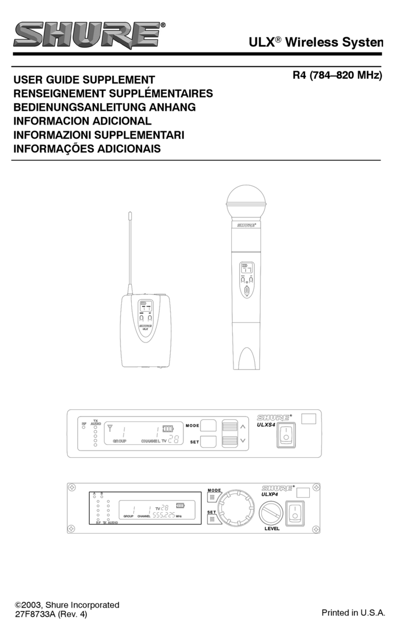
Other Shure Microphone System manuals

Shure
Shure The Twin Pro User manual

Shure
Shure QLX-D User manual

Shure
Shure PA821A User manual

Shure
Shure PGXD User manual

Shure
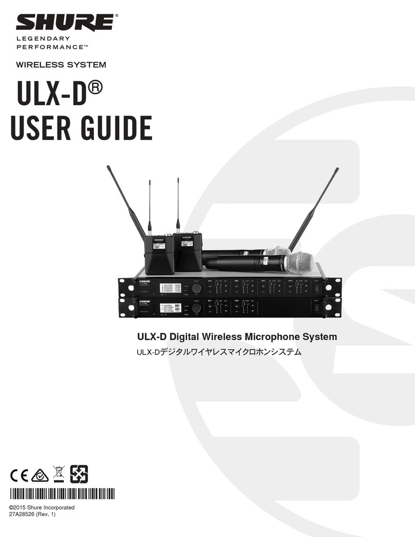
Shure FP Wireless User manual

Shure
Shure UC User manual

Shure
Shure UHF Wireless System Owner's manual

Shure
Shure Sistema Microflex MXCW User manual

Shure
Shure QLX-D User manual

Shure
Shure SC User manual

Shure
Shure UHF-R Wireless User manual

Shure
Shure ULXD8 User manual

Shure
Shure DDS 5900 User manual

Shure
Shure QLX-D User manual

Shure
Shure KCX User manual

Shure
Shure ULXD4E K51 User manual

Shure
Shure 404B User manual

Shure
Shure QLXD4E P51 User manual

Shure
Shure PSM 300 P3RA User manual

Shure
Shure SLX-D User manual