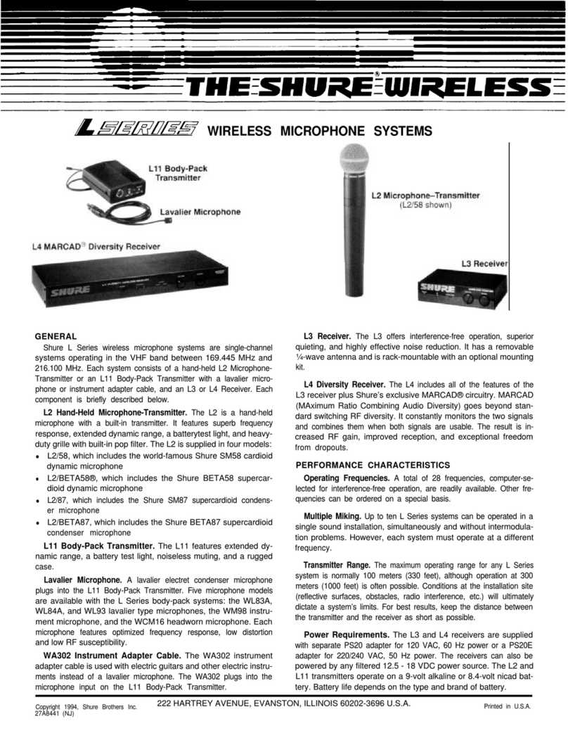
Shure ULX Wireless Microphone System User manual

ULX)Wireless System
User Guide
Ultra-Wide Band Frequency Agile UHF Systems
Auto Frequency Selection (AFS)
Reliable, Pro essional Sound Quality
Multi-System Operation
E2003, Shure Incorporated
27EN8732C (CC) Printed in U.S.A.

2
CONTENTS
ULX)SYSTEM COMPONENTS 3. . . . . . . . . . . . . . . . . . . . . . . . . . . . . . . . . . . . . . . . . . . . . . . . . . . . . . . . . . . . . . . . .
ULXS4 STANDARD RECEIVER FEATURES AND CONTROLS 4. . . . . . . . . . . . . . . . . . . . . . . . . . . . . . . . . . . . .
Front Panel 4. . . . . . . . . . . . . . . . . . . . . . . . . . . . . . . . . . . . . . . . . . . . . . . . . . . . . . . . . . . . . . . . . . . . . . . . . . . . . . . . . . .
Rear Panel 4. . . . . . . . . . . . . . . . . . . . . . . . . . . . . . . . . . . . . . . . . . . . . . . . . . . . . . . . . . . . . . . . . . . . . . . . . . . . . . . . . . .
ULXP4 PROFESSIONAL RECEIVER FEATURES AND CONTROLS 5. . . . . . . . . . . . . . . . . . . . . . . . . . . . . . . .
Front Panel 5. . . . . . . . . . . . . . . . . . . . . . . . . . . . . . . . . . . . . . . . . . . . . . . . . . . . . . . . . . . . . . . . . . . . . . . . . . . . . . . . . . .
Rear Panel 5. . . . . . . . . . . . . . . . . . . . . . . . . . . . . . . . . . . . . . . . . . . . . . . . . . . . . . . . . . . . . . . . . . . . . . . . . . . . . . . . . . .
SINGLE SYSTEM INSTALLATION 6. . . . . . . . . . . . . . . . . . . . . . . . . . . . . . . . . . . . . . . . . . . . . . . . . . . . . . . . . . . . . .
Receiver Connections 6. . . . . . . . . . . . . . . . . . . . . . . . . . . . . . . . . . . . . . . . . . . . . . . . . . . . . . . . . . . . . . . . . . . . . . . . . .
Turning the Receiver On 7. . . . . . . . . . . . . . . . . . . . . . . . . . . . . . . . . . . . . . . . . . . . . . . . . . . . . . . . . . . . . . . . . . . . . . . .
Scanning for the Next Open Channel 7. . . . . . . . . . . . . . . . . . . . . . . . . . . . . . . . . . . . . . . . . . . . . . . . . . . . . . . . . . . . .
Changing the Receiver Group Setting 8. . . . . . . . . . . . . . . . . . . . . . . . . . . . . . . . . . . . . . . . . . . . . . . . . . . . . . . . . . . .
Changing the Receiver Channel Setting 8. . . . . . . . . . . . . . . . . . . . . . . . . . . . . . . . . . . . . . . . . . . . . . . . . . . . . . . . . .
Adjusting the Receiver Display Contrast 8. . . . . . . . . . . . . . . . . . . . . . . . . . . . . . . . . . . . . . . . . . . . . . . . . . . . . . . . . .
ULX1 TRANSMITTER FEATURES AND CONTROLS 9. . . . . . . . . . . . . . . . . . . . . . . . . . . . . . . . . . . . . . . . . . . . . .
ULX2 TRANSMITTER FEATURES AND CONTROLS 10. . . . . . . . . . . . . . . . . . . . . . . . . . . . . . . . . . . . . . . . . . . . .
TRANSMITTER SETUP 11. . . . . . . . . . . . . . . . . . . . . . . . . . . . . . . . . . . . . . . . . . . . . . . . . . . . . . . . . . . . . . . . . . . . . . .
Transmitter Battery Installation 11. . . . . . . . . . . . . . . . . . . . . . . . . . . . . . . . . . . . . . . . . . . . . . . . . . . . . . . . . . . . . . . .
ULX1 Bodypack Connections 11. . . . . . . . . . . . . . . . . . . . . . . . . . . . . . . . . . . . . . . . . . . . . . . . . . . . . . . . . . . . . . . . .
Turning the Transmitter On 11. . . . . . . . . . . . . . . . . . . . . . . . . . . . . . . . . . . . . . . . . . . . . . . . . . . . . . . . . . . . . . . . . . .
Checking Transmitter Battery Power 12. . . . . . . . . . . . . . . . . . . . . . . . . . . . . . . . . . . . . . . . . . . . . . . . . . . . . . . . . . .
ULX1 Bodypack Transmitter Attenuation Settings 12. . . . . . . . . . . . . . . . . . . . . . . . . . . . . . . . . . . . . . . . . . . . . . .
Setting the Transmitter Operating Frequency 12. . . . . . . . . . . . . . . . . . . . . . . . . . . . . . . . . . . . . . . . . . . . . . . . . . .
SYSTEM OPERATION 14. . . . . . . . . . . . . . . . . . . . . . . . . . . . . . . . . . . . . . . . . . . . . . . . . . . . . . . . . . . . . . . . . . . . . . . .
Transmitter Gain Adjustment 14. . . . . . . . . . . . . . . . . . . . . . . . . . . . . . . . . . . . . . . . . . . . . . . . . . . . . . . . . . . . . . . . .
Locking the Transmitter Frequency Settings 15. . . . . . . . . . . . . . . . . . . . . . . . . . . . . . . . . . . . . . . . . . . . . . . . . . . .
Unocking the Transmitter Frequency Settings 15. . . . . . . . . . . . . . . . . . . . . . . . . . . . . . . . . . . . . . . . . . . . . . . . . . .
Locking the Power On/Off Switch 16. . . . . . . . . . . . . . . . . . . . . . . . . . . . . . . . . . . . . . . . . . . . . . . . . . . . . . . . . . . . .
Unlocking the Power On/Off Switch 16. . . . . . . . . . . . . . . . . . . . . . . . . . . . . . . . . . . . . . . . . . . . . . . . . . . . . . . . . . .
ADVANCED RECEIVER PROGRAMMING (ULX4P MODELS ONLY) 17. . . . . . . . . . . . . . . . . . . . . . . . . . . . . . .
Scanning Frequency Groups 17. . . . . . . . . . . . . . . . . . . . . . . . . . . . . . . . . . . . . . . . . . . . . . . . . . . . . . . . . . . . . . . . .
Adjusting the Receiver Squelch Setting 17. . . . . . . . . . . . . . . . . . . . . . . . . . . . . . . . . . . . . . . . . . . . . . . . . . . . . . . .
Locking the Receiver 18. . . . . . . . . . . . . . . . . . . . . . . . . . . . . . . . . . . . . . . . . . . . . . . . . . . . . . . . . . . . . . . . . . . . . . . .
Unlocking the Receiver 18. . . . . . . . . . . . . . . . . . . . . . . . . . . . . . . . . . . . . . . . . . . . . . . . . . . . . . . . . . . . . . . . . . . . . .
RECEIVER MOUNTING 19. . . . . . . . . . . . . . . . . . . . . . . . . . . . . . . . . . . . . . . . . . . . . . . . . . . . . . . . . . . . . . . . . . . . . . .
Table Mounting the ULXS4 Standard Receiver 19. . . . . . . . . . . . . . . . . . . . . . . . . . . . . . . . . . . . . . . . . . . . . . . . . .
Rack Mounting a ULXP4 Professional Receiver 19. . . . . . . . . . . . . . . . . . . . . . . . . . . . . . . . . . . . . . . . . . . . . . . . .
Rack Mounting Dual ULXP4 Receivers 20. . . . . . . . . . . . . . . . . . . . . . . . . . . . . . . . . . . . . . . . . . . . . . . . . . . . . . . .
TIPS FOR ACHIEVING OPTIMUM PERFORMANCE 21. . . . . . . . . . . . . . . . . . . . . . . . . . . . . . . . . . . . . . . . . . . . .
SPECIFICATIONS 21. . . . . . . . . . . . . . . . . . . . . . . . . . . . . . . . . . . . . . . . . . . . . . . . . . . . . . . . . . . . . . . . . . . . . . . . . . . .
CERTIFICATION 22. . . . . . . . . . . . . . . . . . . . . . . . . . . . . . . . . . . . . . . . . . . . . . . . . . . . . . . . . . . . . . . . . . . . . . . . . . . . .
REPLACEMENT PARTS 22. . . . . . . . . . . . . . . . . . . . . . . . . . . . . . . . . . . . . . . . . . . . . . . . . . . . . . . . . . . . . . . . . . . . . .
FURNISHED ACCESSORIES 22. . . . . . . . . . . . . . . . . . . . . . . . . . . . . . . . . . . . . . . . . . . . . . . . . . . . . . . . . . . . . . . . . .
OPTIONAL ACCESSORIES 23. . . . . . . . . . . . . . . . . . . . . . . . . . . . . . . . . . . . . . . . . . . . . . . . . . . . . . . . . . . . . . . . . . .
BATTERY LIFE 24. . . . . . . . . . . . . . . . . . . . . . . . . . . . . . . . . . . . . . . . . . . . . . . . . . . . . . . . . . . . . . . . . . . . . . . . . . . . . .
TROUBLESHOOTING 24. . . . . . . . . . . . . . . . . . . . . . . . . . . . . . . . . . . . . . . . . . . . . . . . . . . . . . . . . . . . . . . . . . . . . . . .
LICENSING INFORMATION 25. . . . . . . . . . . . . . . . . . . . . . . . . . . . . . . . . . . . . . . . . . . . . . . . . . . . . . . . . . . . . . . . . . .
LIMITED ONE–YEAR WARRANTY 26. . . . . . . . . . . . . . . . . . . . . . . . . . . . . . . . . . . . . . . . . . . . . . . . . . . . . . . . . . . . .
DECLARATION OF CONFORMITY 27. . . . . . . . . . . . . . . . . . . . . . . . . . . . . . . . . . . . . . . . . . . . . . . . . . . . . . . . . . . . .

3
ULX)SYSTEM COMPONENTS (FIGURE 1)
ULX1 ULX2
ULXS4
ULXP4
FIGURE 1
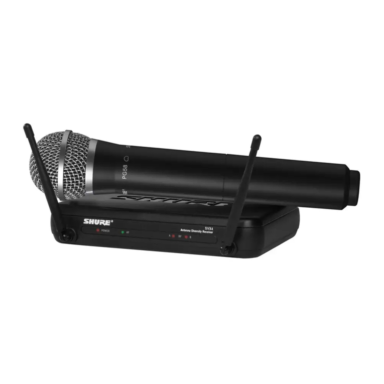
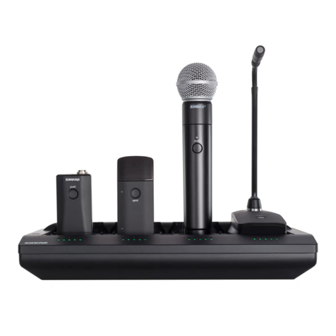
Each Shure ULX£Wireless System includes the following components, as shown in Figure 1:
ULX1 Body-Pack Transmitter with a lavalier microphone, instrument adapter cable, or headworn microphone
or a
ULX2 Hand-Held Microphone Transmitter with an interchangeable Shure microphone head
and a
ULXS4 Standard Diversity Receiver
or a
ULXP4 Professional Diversity Receiver with rack-mounting hardware
or a
ULXP4D Dual Professional Diversity Receivers with rack-mounting hardware and center link brackets

4
ULXS4 STANDARD RECEIVER FEATURES AND CONTROLS (FIGURE 2)
FIGURE 2
Front Panel
1. “RF” Indicator. Glows green to indicate presence of received Radio Frequency (RF) signal.
2. “TX Audio” Level Indicators. Indicate transmitted (TX) audio signal strength. Green indicates normal operation. Am-
ber indicates approaching overload condition. Red indicates excessive audio levels.
3. Receiving Antenna Indicator. Appears on the left or right side of the display, depending on which antenna is receiving
the strongest RF signal.
4. GROUP Display. Indicates the pre-selected compatible Frequency Group number in which the system is operating.
5. CHANNEL Display. Indicates the current Channel number within the Frequency Group.
6. Transmitter Battery Life Indicator. Displays the remaining transmitter battery life when the transmitter is turned on.
7. SCAN Indicator. Appears when Scan Channel Mode is active.
8. TV Channel/Volume Level Indicator. Shows volume level and UHF TV channel in small digits (U.S. only).
9. MODE Button. Press this button to step through the display menu.
10. SET Button. Saves the altered setting.
11. / Button. Press this button to increase or decrease the Volume level, Group/Channel settings or the display contrast
level.
12. Power On/Off Switch. Turns the receiver on and off.
Rear Panel
13. Power Connector. Accepts power from the supplied AC adapter, or from any filtered 14–18 Vdc (550 mA minimum) supply.
It also accepts dc power from a Shure UA844 Antenna Distribution System.
14. Output Connector (XLR balanced Low Z). Provides balanced low–impedance mic level or line level output.
15. Mic/Line Switch. Selects output of XLR balanced Low Z connector. It can be set for microphone (–27 dBV) or line–level
(+4.3 dBV). The Mic/Line switch does not affect the output of the unbalanced 1/4 inch phone jack.
16. Output Connector (High Z Unbalanced 1/4 inch Phone Jack). Provides unbalanced high impedance auxiliary level
output.
17. Antenna Input Connectors. BNC–type connectors provide connection to the supplied antennas. They also provide
12 Vdc output power for use with remotely located antennas.

5
ULXP4 PROFESSIONAL RECEIVER FEATURES AND CONTROLS (FIGURE 3)
FIGURE 3
Front Panel
1. Receiving Antenna Indicators. One of these amberLEDswill glow , depending on which antenna is receiving the stron-
gest Radio Frequency (RF) signal.
2. SQUELCH Indicator. Appears when the Squelch Level Mode is selected.
3. SCAN Indicator. Appears when the receiver is scanning for an open Group or Channel.
4. Volume Level Warning Indicator. Indicates a discrepancy between the Volume control knob position and the previous-
ly locked Volume Level setting.
5. TV Channel Display. Indicates the UHF TV channel in which the system is operating (U.S. only).
6. Transmitter Battery Life Indicator. Displays the remaining transmitter battery life when the transmitter is turned on.
7. Volume Lock Indicator. Appears after the Volume level setting has been locked.
8. RF Level Indicators. Indicate received RF signal strength.
9. “TX Audio” Level Indicators. Indicate transmitted (TX) audio signal strength. Green indicates normal operation. Am-
ber indicates approaching overload condition. Red indicates excessive audio levels.
10. GROUP Display. Indicates the pre-selected Frequency Group number in which the system is operating.
11. CHANNEL Display. Indicates the current Channel number within the Frequency Group.
12. FREQUENCY Display. Indicates the current frequency in megahertz (MHz).
13. Frequency Lock Indicator. Appears when the Frequency has been locked.
14. MODE Button. Press this button to step through the display menu.
15. SET Button. Saves the altered setting.
16. Display Control Knob. Rotate this knob to change the Group/Channel settings, the Squelch setting, or to scan a Group
or Channel.
17. Level Control. Adjusts the receiver audio output level to match the required input levels of a mixer or amplifier. Normally,
this control is set fully clockwise.
18. Power On/Off Switch. Turns the receiver on and off.
Rear Panel
19. Power Connector. Accepts power from the supplied AC adapter, or from any filtered 14–18 Vdc (550 mA minimum) supply.
It also accepts DC power from a Shure UA844 Antenna Distribution System.
20. Output Connector (XLR balanced Low Z). Provides balanced low–impedance mic level or line level output.
21. Mic/Line Switch. Selects output of XLR balanced Low Z connector. It can be set for microphone (–27 dBV) or line level
(+4.3 dBV). This switch does not affect the output of the unbalanced 1/4 inch phone jack.
22. Output Connector (High Z Unbalanced 1/4 inch Phone Jack). Provides unbalanced high impedance auxiliary level
output.
23. Antenna Input Connectors. BNC–type connectors provide connection to the supplied antennas. They also provide
12 Vdc output power for use with remotely located antennas.

6
SINGLE SYSTEM SETUP
Receiver Connections
NOTE: If you are installing multiple ULXP4 Professional systems, or systems with multiple ULXP4 receivers, refer
also to the Advanced Programming section of this manual.
1. Plug the dc power supply into the power connector on the back of the receiver, as shown in Figure 4. Connect the other
end of the power supply into an electrical outlet.
FIGURE 4
2. Attach the two antennas to the ANTENNA connectors, as shown in Figure 5. The ULXS4 is supplied with1/4 wave anten-
nas; the ULXP4 is supplied with 1/2 wave antennas.
ULXS4
ULXP4
FIGURE 5
3. Connect audio cable(s) (not supplied) from the audio output(s) to the audio input(s) of your audio system, mixer and/or
amplifier, as shown in Figure 6.
ULXP4 ULXS4
FIGURE 6

7
4. If the receiver XLR output is used, make sure the MIC/LINE switch setting matches the input requirements of the mixer
or amplifier, as shown in Figure 7. The Mic/Line switch does not affect the output of the unbalanced 1/4 inch phone jack.
MIC LINE
FIGURE 7
Turning the Receiver On
NOTE: These instructions assume no other wireless microphone systems are in use.
CAUTION: Do NOT turn on the transmitter before powering up the receiver. Turning the transmitter on first will in-
terfere with the receiver’s frequency scanning function.
Turn the receiver on by pressing the power On/Off switch. The default Group 1 Channel 1 setting will appear on the
receiver display, as shown in Figure 8.
FIGURE 8
Scanning for the Next Open Channel
1. To enter the Scan Mode, press the MODE button on the receiver once. SCAN CHANNEL will flash on the display, as
shown in Figure 9.
FIGURE 9
2. Press the or buttons (ULXS4) or rotate the control knob (ULXP4) clockwise one quarter turn. The next open Channel
number will appear on the display, as shown in Figure 10.
FIGURE 10
NOTE: If “NO” appears on the display, the receiver has not detected an open Channel in the current Group. Change the
Group according to the instructions on the following page. After changing the Group, repeat Steps 1 and 2 above.
3. To tune the receiver to the new Channel, press the SET button. The display will return to the default mode, as shown
in Figure 11.
FIGURE 11
THE RECEIVER IS NOW READY TO USE.
UNLESS THE RECEIVER IS MOVED TO A DIFFERENT LOCATION, THIS PROCEDURE DOES
NOT NEED TO BE REPEATED. PROCEED TO TRANSMITTER SETUP SECTION.

8
Changing the Receiver Group Setting
1. Press the MODE button twice. The word GROUP will flash on the display, as shown in Figure 12.
FIGURE 12
2. Press the or buttons (ULXS4) or rotate the control knob (ULXP4). The new frequency Group number will appear
on the display, as shown in Figure 13.
FIGURE 13
3. To tune the receiver to the new Group, press the SET button. The display will advance to the Change Channel mode.
Press the MODE button once more to return to the default mode.
NOTE: The receiver always defaults to the first Channel in any new Group.
Changing the Receiver Channel Setting
1. Press the MODE button three times. The word CHANNEL will flash on the display, as shown in Figure 14.
FIGURE 14
2. Press the or buttons (ULXS4) or rotate the control knob (ULXP4). The new Channel number will appear on the dis-
play, as shown in Figure 15.
FIGURE 15
3. To save the new Channel, press the SET button. The receiver will then return to the default mode.
Adjusting the Receiver Display Contrast
Press the MODE button for two seconds.“LCd” will appear on the display, as shown in Figure 16.
FIGURE 16
4. Press the or buttons (ULXS4) or rotate the control knob (ULXP4) to increase or decrease display contrast, as shown
in Figure 17.
FIGURE 17
5. To save the new Contrast setting, press the SET button. The display will return to the default mode.
To return to the default mode without changing the display contrast setting, press the MODE button.

9
ULX1 TRANSMITTER FEATURES AND CONTROLS (FIGURE 18)
FIGURE 18
1. Antenna. A flexible 1/4 wave antenna is permanently attached to the top of the ULX1 transmitter.
2. Input Connector. This TA4F miniature four-pin connector mates with a variety of Shure lavalier, instrument and headset
microphones and cables.
3. Power ON/OFF Switch. Turns transmitter power on and off.
4. Power/Battery LED. When the Power switch is in the ON position, this LED will glow green, indicating that the transmit-
ter is on. This LED will turn red when the battery is low. Refer to the “Checking the Transmitter Battery Power” paragraph.
5. Display Window. Displays Group and Channel setting, battery power level, and PEAK indicator.
6. Battery Level Icon. Indicates amount of battery life remaining.
7. PEAK Icon. This icon appears when audio input signal overloads the transmitter. The icon is displayed for 2 seconds
after the input overload is detected.
8. GROUP Display. Indicates the frequency Group number in which the transmitter is operating.
9. CHANNEL Display. Indicates the current Channel number within the frequency Group.
10. MODE Button. Selects Group or Channel mode.
11. SET Button. Changes Group or Channel setting.
12. Audio Gain Control. Changes the audio level sensitivity to accommodate various sound sources (e.g. loud singing,
soft speaking, or musical instrument). Refer to the “Transmitter Gain Adjustment” paragraph.
13. Input Attenuation Switch. Selects either 0 dB or –20 dB attenuation. Use the 0 dB position for voice and low output
instruments. Use the 20 dB pad position for high output instruments such as electric guitars with active electronics.
14. Belt Clip. Allows the transmitter to be worn on a belt, waistband, or guitar strap.
15. Battery Compartment Cover. Hinged cover opens to provide access to 9V battery.

10
ULX2 TRANSMITTER FEATURES AND CONTROLS (FIGURE 19)
Ñ
FIGURE 19
1. Grille. Protects the microphone cartridge and helps reduce breath sounds and wind noise. The grilles of the various
microphone heads differ in appearance.
2. Display Window. Displays Group and Channel setting, battery power level, and PEAK indicator.
3. Battery Level Icon. Indicates amount of battery life remaining.
4. PEAK Icon. This icon appears when the input signal overloads the transmitter. The icon is displayed for 2 seconds after
input overload is detected.
5. GROUP Display. Indicates the frequency Group number in which the transmitter is operating.
6. CHANNEL Display. Indicates the current Channel number within the frequency Group.
7. MODE Button. Selects Group or Channel mode.
8. SET Button. Changes Group or Channel setting.
9. Power/Battery LED. When the Power switch is in the ON position, this LED will glow green, indicating that the transmit-
ter is on. This LED will turn red when the battery is low. Refer to the “Checking the Transmitter Battery Power” paragraph.
10. Power ON/OFF Switch. Turns the transmitter on and off.
11. Audio Gain Control. Changes the audio level sensitivity to accommodate various sound sources (e.g. loud singing
or soft speaking). Refer to the “Transmitter Gain Adjustment” paragraph).
12. 9 V Battery. Provides power to the transmitter and microphone.
13. Battery Cover. Unscrews to expose battery and Gain control.

11
TRANSMITTER SETUP
Transmitter Battery Installation
Open the battery cover and insert a fresh 9V alkaline or lithium battery, as shown in Figure 20.
Ñ
Ñ
FIGURE 20
ULX1 Bodypack Connections
If you are using a Bodypack system with a Shure lavalier microphone or instrument adapter, plug the microphone cable or
instrument adapter cable into the transmitter input connector, as shown in Figure 21.
NOTE: The wiring of the input connector on the transmitter is designed for Shure microphones.
FIGURE 21
Turning the Transmitter On
NOTE: DO NOT turn on the transmitter before powering up the receiver. Once the receiver has located an open
frequency, turn the transmitter on and set it to that receiver frequency. Turning the transmitter on first will interfere
with the receiver’s frequency scanning function.
Slide the transmitter ON/OFF switch to the ON position, as shown in Figure 22. The power LED will momentarily glow red,
then change to a steady green. The default frequency setting (Channel 1, Group 1) will appear on the display.
FIGURE 22

12
Checking Transmitter Battery Power
With the transmitter turned on, observe the Battery Level icon on the display. The number of shaded bars on the icon indicate
the approximate amount of battery life remaining, as shown in Figure 23.
NOTE: Stated battery life is based on a 9V Duracell alkaline battery. For details on other battery types, refer to the “Battery
Life” paragraph, or go to the Shure web site at www.shure.com and refer to the FAQ section. Once the empty battery icon
appears, the tone key turns off and the receiver will mute.
|6 – 8 hours
|2 – 6 hours
|0 – 2 hours
= 0 hours
FIGURE 23
ULX1 Bodypack Transmitter Attenuation Settings
If using a lavalier microphone, make sure the Attenuator switch is in the 0 dB position. If using an instrument adapter cable,
slide the Attenuator switch to the –20 dB position. Refer to Figure 24.
FIGURE 24
Setting the Transmitter Operating Frequency
1. Note the Group number and Channel number on the receiver display. Press and hold the MODE button until only the
Group number is visible on the transmitter display, as shown in Figure 25.
FIGURE 25
2. If necessary, press the transmitter SET button to advance the Group number until it matches the Group number on the
receiver display.
3. Press the transmitter MODE button again to select the new Group setting and move to the Channel selection mode.
The Group number will disappear, and only the Channel number will be visible. Refer to Figure 26.
FIGURE 26

13
4. Press the SET button to advance to the desired Channel number, as shown in Figure 27.
FIGURE 27
5. To reverse the direction of the Group or Channel search, hold down the SET button and press the MODE button. See
Figure 28.
FIGURE 28
6. Press the MODE button again to select the new Channel setting. “FrCh” will appear briefly on the display, indicating
that the frequency has changed. Then the new Group and Channel settings will appear. Refer to Figure 29.
FIGURE 29
7. Make sure the transmitter Group and Channel settings match the receiver Group and Channel settings, as shown in
Figure 30. If using the Bodypack transmitter, clip it to your belt, waistband, or guitar strap.
ULXS4 ULXP4
FIGURE 30
THE TRANSMITTER IS NOW READY TO USE. FOR MULTIPLE SYSTEM INSTALLATIONS,
LEAVE THE TRANSMITTER ON, RETURN TO THE “BASIC RECEIVER PROGRAMMING,” AND
REPEAT THE SETUP PROCEDURE FOR EACH SYSTEM.

14
SYSTEM OPERATION
Speak into the microphone or play your instrument. If your audio system is properly set and functioning, you should hear
the sound of your voice or instrument coming through the loudspeakers. The LEDs on the receiver should also illuminate.
The top TX AUDIO LED is red and should only illuminate momentarily when you speak loudly or play your instrument loudly.
Refer to Figure 31.
ULXS4
ULXP4
FIGURE 31
Transmitter Gain Adjustment
If necessary, adjust the transmitter gain with the supplied screwdriver, as shown in Figure 32, until only the green and yellow
Audio LEDs on the receiver illuminate when you speak into the microphone or play your instrument. The red LED should
only illuminate momentarily when you speak loudly or play your instrument loudly.
FIGURE 32

15
Locking Transmitter Frequency Settings
1. Refer to Figure 33. Slide the transmitter power switch to the OFF position and wait for the display light to turn off.
2. Hold down the SET button.
3. Slide the power switch back to the ON position. “Fr L” will appear on the transmitter display, indicating that the frequency
setting is locked. The locked frequency Group and Channel will then appear.
1
ULX2ULX1
345
2
45
2
3
1
FIGURE 33
Unlocking Transmitter Frequency Settings
1. Refer to Figure 34. Slide the transmitter power switch to the OFF position and wait for the display light to turn off.
2. Hold down the SET button.
3. Slide the power switch back to the ON position. “Fr UL” will appear on the transmitter display,indicating that the frequency
setting is unlocked. The current frequency Group and Channel will then appear.
1
ULX2ULX1
345
2
45
2
3
1
FIGURE 34

16
Locking the Power On/Off Switch
1. Turn the transmitter on by sliding the power switch to the ON position.
2. While holding down the SET button, press and hold the MODE button for four seconds. “Po L” will appear on the display.
See Figure 35. This display indicates that the Power On/Off switch is locked. The transmitter will remain on, even when
the power ON/OFF switch is moved to the OFF position.
NOTE: Make sure both buttons are depressed when trying to lock the transmitter.
2132
1
3
ULX1 ULX2
FIGURE 35
Unlocking the Power On/Off Switch
1. Verify that the power transmitter ON/OFF switch is in the ON position.
2. While holding down the transmitter SET button, press and hold the MODE button for four seconds. “Po UL” will appear
on the display. See Figure 36. This display indicates that the Power On/Off switch is unlocked. The transmitter will then
return to normal operating mode.
NOTE: Make sure both buttons are depressed when trying to unlock the transmitter.
2132
1
3
ULX1 ULX2
FIGURE 36

17
ADVANCED PROGRAMMING MODE (ULXP4 MODELS ONLY)
Scanning Frequency Groups
1. Hold down the receiver SET button and press the MODE button once. The words GROUP and SCAN will flash on the
display. Refer to Figure 37.
FIGURE 37
2. To begin scanning, rotate the control knob one quarter turn clockwise, as shown in Figure 38. The receiver will automati-
cally begin scanning each Channel in all Groups. This may take up to two minutes, and the word “bUSY” will appear
on the display.
FIGURE 38
3. When all Groups have been scanned, the Group with the most open Channels will appear on the display, as shown in
Figure 39.
FIGURE 39
4. To tune the receiver to the new Group, press the SET button. An open Channel in this Group will automatically be
scanned and saved in the background. The display will then return to the default mode, as shown in Figure 40. If you
choose not to accept the receiver’s recommended Group, rotate the control knob to the right to scroll through the list
of scanned groups.
FIGURE 40
Adjusting the Receiver Squelch Setting
The receiver squelch control is factory preset for optimum performance. Normally, no further adjustment is required. Howev-
er, it is possible to adjust the squelch control to improve either signal quality or increase system range.
NOTE: Increasing the Squelch level causes the receiver to demand a higher quality signal (less noise before muting), but
it reduces operating range. Decreasing the Squelch level allows a lower quality signal through (more noise before muting),
but extends the operating range.
1. Hold down the receiver SET button and press the MODE button twice. “SQLCH” will flash on the display, as shown in
Figure 41.
FIGURE 41

18
2. Rotate the control knob. The new Squelch setting will appear on the display, as shown in Figure 42.
FIGURE 42
3. To accept the new Squelch value, press the SET button. The display will then return to the Default Mode, press the MODE
button again.
Locking the Receiver
You can lock the ULXP4 receiver frequency and output level to prevent unauthorized or accidental changes to the settings.
To access the Lock functions, proceed as follows:
1. Hold down the receiver SET button and press the MODE button three times. “Loc” will appear on the receiver display.
See Figure 43.
FIGURE 43
2. Rotate the control knob until one or both of the lock icons flashes on the receiver display, as shown in Figure 44.
FIGURE 44
3. To activate the flashing lock icon(s), press the SET button. The display will return to the default mode and the lock icon
will appear on all display screens. See Figure 44.
FIGURE 45
Unlocking the Receiver
To unlock the ULXP4 receiver frequency and output level settings, hold down the SET button and rotate the control knob
one quarter turn left-right-left. The lock icon(s) will disappear, indicating that the receiver is unlocked. See Figure 45.
FIGURE 46
NOTE: If the volume control knob has been set to a level higher than the locked level, the output level will remain locked
and the Volume Level warning indicator will flash on the receiver display. See Figure 46. Rotate the volume control knob
counterclockwise until the Volume Level warning indicator stops flashing. This will unlock the output level setting.
FIGURE 47

19
RECEIVER INSTALLATION
Table Mounting the ULXS4 Standard Receiver
To mount a ULXS4 Standard receiver on a table or other horizontal surface, attach the four adhesive bumpers to the bottom
corners of the receiver and place the receiver on the mounting surface. See Figure 47.
Ñ
Ñ
ÑÑÑÑÑÑÑÑ
Ñ
Ñ
Ñ
Ñ
FIGURE 48
NOTE: The ULXS4 can also be rack mounted, using one of the Rack Mount Kits listed on page 24.
Rack Mounting a ULXP4 Professional Receiver
1. Align the supplied rack-mount brackets over the holes on each side of the receiver, as shown in Figure 48.
2. Fasten the brackets to the receiver by installing the eight screws supplied with the mounting brackets.
CAUTION: Do not overtighten the screws. Doing so may damage the printed circuit boards.
ÑÑÑ
ÑÑÑ
ÑÑÑ
ÑÑÑÑÑÑÑ
ÑÑÑÑÑÑÑ
ÑÑÑÑÑÑÑ
Ñ
Ñ
ÑÑÑÑÑÑÑ
Ñ
Ñ
ÑÑ
Ñ
Ñ
1/4 IN.
FIGURE 49
3. Slide the receiver into an 19-inch audio equipment rack, as shown in Figure 49.
4. Secure the rack-mount brackets to the rack using the four supplied screws.
5. If you are not front mounting the antennas, insert the plastic plugs into the bracket holes.
FIGURE 50
NOTE: Front–mounting the antennas requires the UA600 Front Mount Antena Kit listed on page 24.

20
Rack Mounting Dual ULXP4 Receivers
1. Align the receivers side by side so that the front panels both face the same direction.
2. Place the supplied straddle bars in the recesses on the top and bottom of the receivers, so that the bars overlap both
receivers. Refer to Figure 50.
Ñ
Ñ
Ñ
1/4 IN.
FIGURE 51
3. Secure the straddle bars to the receivers using the supplied screws.
CAUTION: Do not overtighten the screws. Doing so may damage the printed circuit boards.
4. Position the rack-mount brackets over the holes in the sides of each receiver, as shown in Figure 51.
5. Secure the brackets to the receivers with the supplied screws.
ÑÑÑ
ÑÑÑ
ÑÑÑ
Ñ
ÑÑÑ
ÑÑÑ
ÑÑ
ÑÑ
Ñ
Ñ
Ñ
Ñ
Ñ
Ñ
Ñ
Ñ
1/4 IN.
Ñ
Ñ
Ñ
FIGURE 52
6. Slide the linked receivers into a 19-inch audio equipment rack, as shown in Figure 52.
7. Secure the brackets to the rack using all four of the supplied screws.
Ñ
ÑÑ
ÑÑ
ÑÑ
Ñ
Ñ
Ñ
Ñ
FIGURE 53
NOTE: To front mount or combine antennas, use the optional accessories listed on page 24.
This manual suits for next models
6
Table of contents
Other Shure Microphone System manuals

Shure
Shure BLX4RE-H8E Technical manual

Shure
Shure UA844 User manual

Shure
Shure ULX Wireless System User manual

Shure
Shure PS21 User manual

Shure
Shure ULXS4 User manual

Shure
Shure Performance Gear User manual

Shure
Shure PSM1000 User manual

Shure
Shure MXW User manual

Shure
Shure PSM 200 User manual

Shure
Shure MV51 User manual

Shure
Shure Microflex MXW User manual

Shure
Shure KSM11 User manual

Shure
Shure PGX Wireless System Specification sheet

Shure
Shure PGXD User manual

Shure
Shure ULX-D User manual

Shure
Shure MICROFLEX MXW User manual

Shure
Shure PSM 900 Quick start guide

Shure
Shure MXA-MUTE User manual

Shure
Shure PA421B User manual

Shure
Shure QLX-D User manual