9
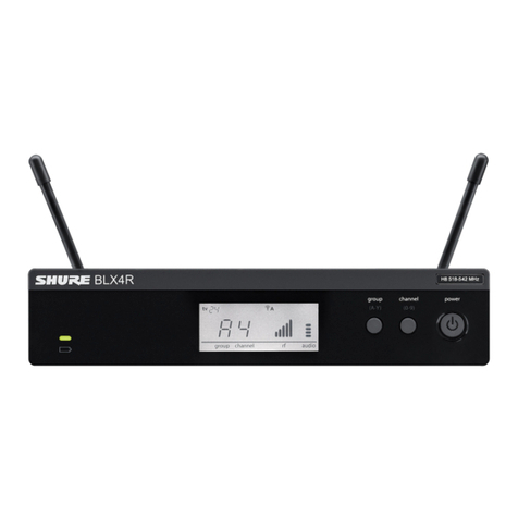
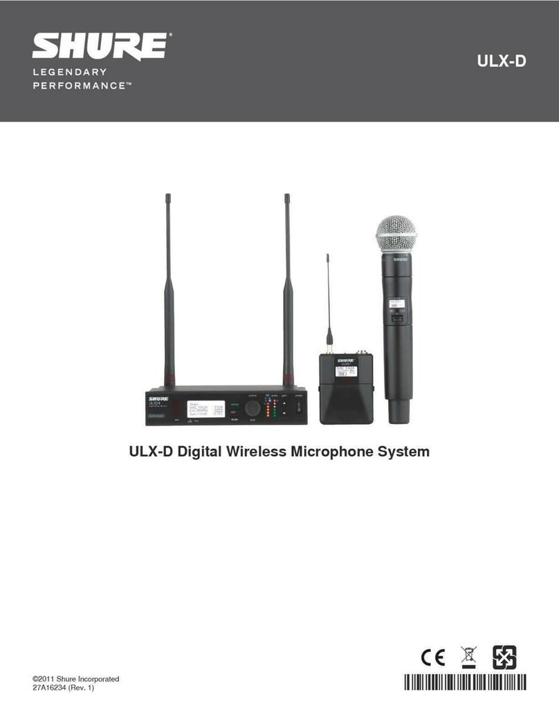
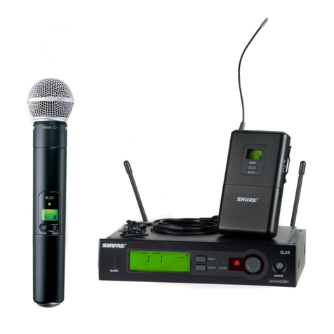
ULXS4, ULXP4
Dimensions ULXS4: 43 x 214 x 163 mm (1.72
x 8.56 x 6.52 in.), H x
W x D
ULXP4: 43 x 214 x 172 mm (1.72
x 8.56 x 6.88 in.), H x
W x D
Weight ULXS4: 1049 g (2 lbs, 5 oz.)
ULXP4: 1105 g (2 lbs, 7 oz.)
Power Requirements 14–18 V DC (negative ground), 550 mA
Audio Output
Configuration XLR Output: Active Balanced
6.35 mm (1/4”)
output: Unbalanced
Impedance XLR Output: MIC setting: 1848Ω
LINE setting: 75Ω
6.35 mm (1/4”)
output: 3kΩ
Maximum Audio Output Level
Ref. ±38 kHz deviation with 1 kHz
tone
XLR connector
(into 600 Ω load):
MIC setting: −17dBV
LINE setting: +3.9 dBV
6.35 mm (1/4”)
connector (into
3 kΩ load):
−2dBV
Pin Assignments XLR Output: 1=ground, 2=hot, 3=cold
6.35 mm (1/4”)
connector: Tip=audio, Ring/Sleeve=ground
Receiver Antenna Input
Connector Type BNC
Impedance 50Ω
Nominal Input Level −95to−30dBm
Maximum Input Level −20dBm
DC bias 12 V DC, 150 mA, maximum
Transmitter Input
Configuration Unbalanced, active
Impedance 20kΩ
Maximum Input Level
1 kHz at 1% THD 12 dBV (10 Vp-p)
Transmitter Input
Connector 4-Pin male mini connector (TA4M)
Configuration Unbalanced, active
Impedance Microphone: 75kΩ
WA302: 1MΩ
Maximum Input Level
1 kHz at 1% THD
Microphone: −4dBV(1.82Vp-p)
WA302: PAD OFF (0dB): 5 dBV (5
Vp-p)
PAD ON
(−20dB):
25 dBV (50
Vp-p)
Pin Assignments
TA4M
1: ground (cable shield)
2: + 5 V Bias
3: audio
4: Tied through active load to ground (On instrument
adapter cable, pin 4 floats)
ULX2
Gain Adjustment Range 20 dB
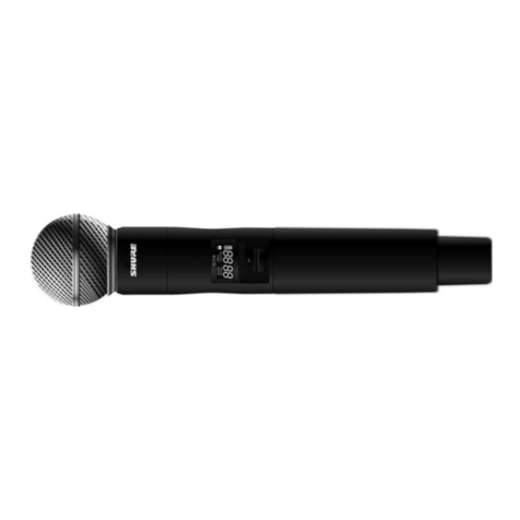
Dimensions SM58: 229 x 51 mm (9 x 2 in.),
L x Dia.
BETA 58: 221 x 51 mm (8.7 x 2 in.),
L x Dia.
SM86: 213 x 49 mm mm (8.4 x
1.9 in.), L x Dia.
SM87/BETA 87: 223 x 51 mm (8.8 x 2 in.),
L x Dia.
Weight SM58/BETA 58: 289 g (10.2 oz.) without
batteries
SM86: 251 g (8.8 oz.) without
batteries
SM87/BETA 87: 258 g (9.1 oz.) without
batteries
Power Requirements 9 V alkaline
RF Output Power 30 mW maximum
varies by region
ULX1
Gain Adjustment Range 25 dB
Attenuation Switch 0,−20dB
Dimensions 96.5 x 67 x 26.7 mm (3.86 x 2.68 x 1.10
in.), H x W x D
Weight 79 g (2.8 oz.) without batteries
Power Requirements 9 V alkaline
Input Impedance 1MΩ
RF Output Power 30 mW maximum
varies by region
SPECIFICATIONS
RF Carrier Range 470,000–865,000 MHz
varies by region
Working Range 100 m (300 ft) typical
Note: Actual range depends on RF signal
absorption, reflection and interference.
Audio Frequency Response 25–15 kHz, ±2 dB
Note: Dependent on microphone type
Modulation ±38 kHz deviation compressor-expander
system with pre- and de-emphasis
Dynamic Range >100 dB, A-weighted
Image Rejection 80 dB, typical
RF Sensitivity 1.26 µV for 12 dB SINAD, typical
Spurious Rejection 75 dB, typical
Ultimate Quieting
Ref. ±38 kHz deviation with 1 kHz
tone
>105 dB, A-Weighted
Total Harmonic Distortion
Ref. ±38 kHz deviation with 1 kHz
tone
0.3%, typical
Operating Temperature Range -20°C (-4°F) to 49°C (120°F)
Note: Battery characteristics may limit
this range.
Polarity Positive pressure on microphone dia-
phragm (or positive voltage applied to tip
of WA302 phone plug) produces positive
voltage on pin 2 (with respect to pin 3 of
low-impedance output) and the tip of the
high impedance 1/4-inch output.
Battery Life 8 to 9 hours (9 V alkaline)
