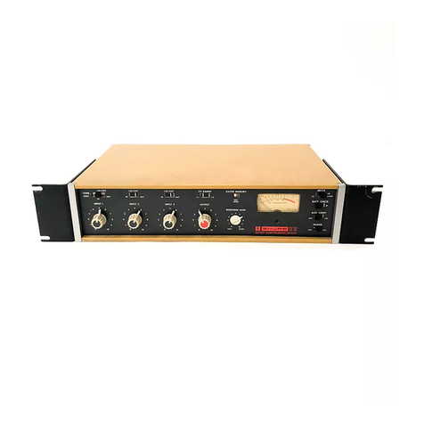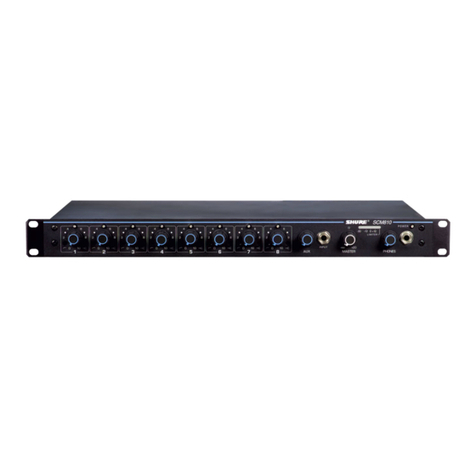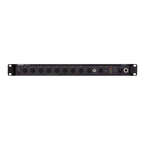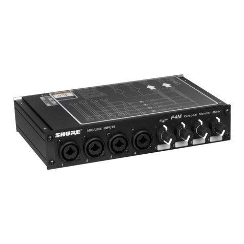
Shure AMS8100 Automatic Microphone Mixer
5
25A1041 (RA)
Characteristics
VR801 is an adjustment pot that changes the dc level at U807, pin 5,
effectively changing the “acceptance angle” of the AMS microphone.
This angle is factory pre-set to 120 degrees, which is 9.5 dB difference
between the front and rear microphone capsules.
Maxbus
The Maxbus tries to turn on only one microphone that hears the
same signal. If three microphones are connected to a unit and spoken
into, only one microphone should turn on.
The Maxbus circuitry is comprised of U805C, U804B, U803C, and
their associated components. The rectified signal from above is fed into
the Maxbus circuitry via U805C. U805C steps the signal up by 6 dB
(2 times) if a channel is turned on. The signal is then fed to U804B which
connects the signal to the actual Maxbus (Link D).
If the signal from a given channel is the highest of all the channels
connected to the Maxbus, then the lower half of D815 will be conducting.
If the signal is not the highest, then that diode will be reverse biased.
U803B checks to see if the diode is conducting. If it is conducting, then
the Maxbus criterion has been met, and U803B, pin 1, goes high. If the
output of U803B and U803A goes high, the channel will gate on.
Last Mic Lock On
The Last Mic Lock On circuit keeps the last microphone that was
activated turned on.
The first sub-block that feeds all of the circuits is the full-wave
rectifier circuit comprised of U106 and its associated components. C824,
C827, C828, C829, R8115, R8116, and R8117 form a filter circuit that
only passes mid-band frequencies. On positive half cycles, U806, pin 2,
causes pin 1 to go low, which turns on Q808. This directs all of the cur-
rent flowing through R8106 down through Q808 and into C823. On the
negative half cycles Q808 is turned off, and no current flows through it.
The negative half cycles are inverted by U806D and then rectified in the
same way as above by U806B. C823, R8107, and R8108 form a filter
for the rectified signal. U806C buffers this rectified signal for subsequent
circuitry.
Hold Time Circuit
When a channel is allowed to turn on, U803C, pin 8, goes higher
than U803C, pin 9. This pulls the output of U803C low, immediately
discharging C819. This, in turn, brings U802A, pin 5, lower than U802A,
pin 4, causing the output of U802A to go low (ground). This causes the
transistors to turn the optoisolator on, thus turning the channel on.
After the channel is on and the decision is made to turn it off, the
output of U803C changes to high-impedance. U802A, pin 5, does not
immediately go high, however. C819 gets charged up via R8062 and
R8061. The channel will go off after the voltage across C819 reaches
the level at U802, pin 4 (hold time bus). This is typically about 0.4
