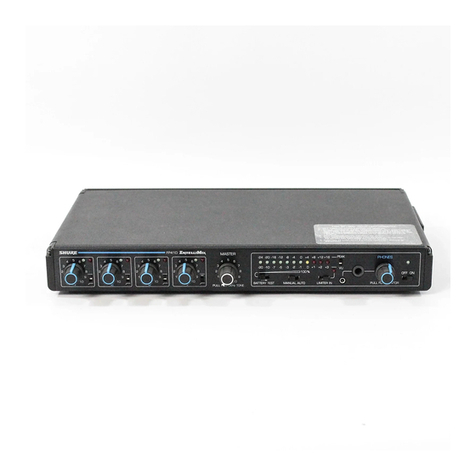
A single-pincoaxial
12
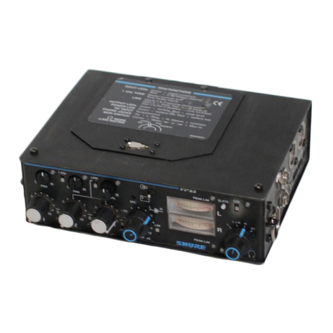
Vdc external power,jack.permits the mixer The mixer requires 11to 18Vdc for operating power. Inter-
to be powered froman-11 io 18 volt source such as a video tape nal power is supplied by two standard rectangular 9-volt
The three &socket professional audio input connec- recorder,
automotive
electrical system or ac power converter. Such
P
alkaline-batteries(Duracell
K~1604 ~r<~u~valent)w~ch-
tors are individually switchable to balanced 600-ohm an external source will also provide simplex power to the also provlde s~mplex(phantom) power to the
microphone
line or low-impedance microphone level. In the MIC microphone inputs, but a battery is still required for A-B power. inputs. Battery life
IS
approximately 8 hours.
position, either simplex (phantom) or A-B power
IS
I
IMPORTANT: Use only alkaline batteries.
available at each input for powering condenser
____I
microphones. Each input transformer is Mumetal
t
shielded for maximum resistance to electrical hum. When powering the mixer from an external source, the batteries A thi~d-91volt-batte~:is used to supply
may be left in place as backup in case of failure of the source. ~3-~owerat each microphone input.
Switchover to battery power is performed by removing the plug When the ~nputselector switch is in the
from the 12Vdc jack. To prevent the possibility of damage caused Line
position,
the power is automatically
by leaking batteries, remove the batteries during any prolonged off for that input.
period of storage or nonuse.
t
--
--
Using .the.-On10ff-switch to turn the power on
starts the green Power On indicator LED
-
flashing
.
..
-
--
.
---
-
!
with a repetition rate of approxima~ly1 second.
I
The LEDcontinues to flash so long as the switch
1
The Slate-pushbutton inserts a 1-second low-frequency
tone (400 Hz) each time it is depressed, and it keeps the
slate microphone on as long as it is depressed. is on.
-..-
.
..
-..-.-
-,
Individual Lo-Cutfilter switches for each inputreduce low- The VU-Meterissupplied set for 0
,
frequency interference from air-conditioner or fan noise, VU
=
+
4
dBm. This level can be
-
wind, strong hum fields, or similar sources. The filters in- changed by an internal adjust-
,
sert a 7 dB rolloff at 100 Hz with a slope of -6 dB per oc- ment (see section on VU Meter
,
tave. Adjustment).
I
The
Limiteflhreshold-and-VU-Meter_tfimpots
are
locatedthrough screwdriver slots below the bat-
tery compartment and to the left of the Simplex or A-B power is selected by
-
--
-
---
-
means of switches directlybelow the battery
A-BISimplex switches.
The VU Lama bushbutton momentarilv il-
compartment, inside the battery door. Inthe
DYN position, no power is supplied to the
Mic inputs.
---
-
-
luminates ;he Zier dlal:~; automatic timed
release shuts off the lamp after 5 seconds. The
lamp remains lit while the button is depressed.
7
A13
5
mm mini jack provides an Aux-level Tape
iiL--
-
--
output with minimum clipping level of 0.5V RMS
(-6
dBV).
On Channel-1,-the. Gain-Control- knob-
pulls out to activate a 1 kHz tone
oscillator that serves as a level-setting
aid. The oscillator level is set with the
--
Master control and is indicated on the
VU Meter.
The-re<Peal&ED flashes to indicate the onset
of limiting.When the Limiter is Out, the red LED
acts as an overload indicator and begins
flashing at 6 dB below output clipping level.
The Battery check pushbutton converts the VU
L
~ecrto a7battery
condition
orcircuit voltage in-
dicator while the button is depressed.
s7
i
A built-in pushbutton-operated, electret condenser
slate microphone can be used either for identifying
-
-
recorded segments or as an emergency field,
microphone.
The Master gain control sets the output level at the
;
LinelMic and~a~e~ut~u~s.Gain is 40 dB from Mic In to
Mic Out or from Line Into Line Out; 90 dB from Mic In to
r
Each input-channel-has-its own-gain-
control. The input clipping-level for Ab.5-mm-minijack and a quarjerjnchphonejack-
provide two stereo headphone outputs that can
microphones is from -47 to
-
17dBV
depending on the channel control set-
ting. For line inputs, the clipping level
ranges from +3 to +33 dBV, again
depending on the control setting.
Line Out, 68 dB from Mic In to Tape Out, and 18 dB from
J
Line Into Tape Out.
s
!
be used simultaneously. They are designed to
drive mono or stereo headsets with impedances
of 8to2,000 ohms. Theycanalsobeusedtodrive
up to four Aux-level tape recorder or amplifier in-
puts.
s
Abeparate Phones volume control sets the level
at the TCa~~eF~tpGt~;-maxii~moutput is
1.6V RMS
(
+
4 dBV) to 200 ohms.
I
Two 3-pin professional audio output
-
--
-
-
--
---
--
-
-
,
connectors are individually switchable to
--
-
600-ohm Gne level or
I&-impedance
microphone level. Minimum clipping levels
are
+
18 dBm (Line)and -34 dBV (Mic).
The output Limiter has a threshold of
+
14 dBm at the
-
--
600-ohm Line output (4 dB below clipping), with com-
parable levels at the Mic and Tape outputs. The
threshold can be internally adjusted down to +3 dBm
(see section on Limiter Threshold Adjustment). The
Limiter attack time is
3
msec typical, with 500 msec
typical recovery time, for unobtrusive operation.

