Shure SCM820 Digital IntelliMix User manual

SCM820
SCM820 Digital IntelliMix Automatic Mixer
®
The Shure digital automatic mixer, SCM820, user guide.
Version: 4.0 (2021-C)

Shure Incorporated
2/59
Table of Contents
SCM820 SCM820 Digital IntelliMix® Automatic Mixer 4
Overview 4
IntelliMix® Operating Principles 4
Mixer Modes 4
Dual Mixer Operation 5
DFR and Audio Processing 5
Model Variations 5
Hardware Interface 6
Front Panel 6
Rear Panel 8
Signal Path Diagram 11
Operating the Mixer 12
Front Panel Modes 12
Audio Mute and Bypass 13
Monitoring 13
SCM820 Application 15
System Requirements 16
Accessing the SCM820 application 16
Installation 17
Power 17
Rackmounting 17
Typical Audio Connections 18
Configuring the Inputs and Outputs 19
Setting IntelliMix 23
Mixer Mode Descriptions 23
IntelliMix Parameters 26
Selecting the Mixer Mode 26
Single or Dual Mixer Operation 27
Networking 27
Network Overview 28
Digital Audio Networking 29
Dante Software by Audinate 34
Dante Controller 34
Dante Virtual Soundcard 34
Application Examples and Advanced Mixer Settings 34
Creating a Link Group 34
Integrating with Other Systems 35
Advanced Mixer Settings 36
Web conferencing 37
Digital Feedback Reduction (DFR) 38
Function 38
Basic DFR Setup 38
Filter Width 39
SCM820 Application 39
Navigation Bar 40
Input Tab 41
Intellimix Tab 43
Digital Feedback Reduction (DFR) Tab 45
Output Tab 46
Preferences Tab 47
Troubleshooting 49
Front-Panel Error Messages 52
Accessories 52
Furnished Accessories 52
Specifications 53
IP Ports and Protocols 56
Connector Diagrams 57

Shure Incorporated
4/59
•
•
•
•
SCM820
SCM820 Digital IntelliMix Automatic Mixer
Overview
TheShureSCM820isan8-channeldigitalautomaticmixerdesignedforuseinspeechapplications,includingsoundreinforce-
ment, broadcasting and audio recording. It dramatically improves audio quality in any application where multiple microphones
are required. The mixer uses IntelliMix technology to select channels to open to the mix bus, while attenuating other channels.
The mixing mode is selectable to allow a range of automatic mixing styles.
IntelliMix Operating Principles
Expanding upon Shure's classic SCM810 IntelliMix technology, the digital SCM820 delivers seamless automatic mixing by
combining the following functions:
Noise Adaptive Threshold (NAT) manages the audio system by distinguishing between dynamic audio (such as speech)
and the noise floor (such as air conditioning). It continuously adjusts the activation threshold, so that only speech levels
louder than the background noise open a channel.
MaxBus ensures that only one channel is opened per sound source, reducing comb filtering for clear, intelligible speech.
Number of Open Microphones Attenuation (NOMA)attenuatessystemgainasadditionalchannelsareopened,provid-
ing consistent output levels and better gain before feedback.
Maintainstheperceivedambientsoundtoachieveanaturalsoundingaudioprogramevenduringlongpausesinconver-
sation.
Mixer Modes
The mixer operates in one of five Mix Modes: Classic, Smooth, Extreme, Custom or Manual. The first three are factory settings
that offer a range of reliable automixing styles. IntelliMix is configurable in Custom mode and turned off in Manual mode.
Classic
ClassicmodeemulatesthedefaultsettingsoftheclassicShureSCM810automixer.Itisrenownedforfast-acting,seam-
less channel gating and consistent perceived ambient sound levels.
Smooth
Smooth mode dynamically balances system gain between open and closed channels. The system gain remains consistent
by distributing gain across channels to equal one open channel. This mode incorporates IntelliMix operating principles into
a gain sharing mixing style.
Extreme
Extreme is an aggressive variation of Classic mode, configured to achieve maximum gain before feedback by completely
attenuating closed channels.
Custom
Custom mode allows individual IntelliMix parameters to be fine-tuned and tailored from the GUI.
Manual
®
®
®
Shure Incorporated
5/59
Manual mode deactivates IntelliMix to operate as a standard mixer. Channel and mix equalization, output limiter and mix
bus routing are still active in this setting.
Dual Mixer Operation
The SCM820 can operate as a single or dual mixer:
Single Mixer: Channels are routed to a single mix bus that sends the same audio to both Mix A and B outputs. This allows the
same program to be sent to different rooms or recording applications. Output gain, parametric equalizer and limiter can be set
separately for each mix.
Dual Mixer: Two separate buses provide independent automixes for each mix output. This allows two entirely different mixes
to result from the same set of inputs. This is useful when the mixer is being used for two applications. For example, set Mix A to
Classic mode for sound reinforcement, and set Mix B to Smooth for a broadcast feed. As a dual mixer, channels can be routed
to Mix A, Mix B, Mix A and B, or neither mix bus.
DFR and Audio Processing
TheSCM820featurestwochannelsofDigitalFeedbackReducer(DFR).DFRusesShure’spatentedAdaptiveNotchFilteral-
gorithm to detect feedback and deploy up to 16 narrow-band notch filters, dramatically improving gain-before-feedback in a
sound reinforcement system. DFR can be applied to any two channels of the SCM820, including the mix outputs.
Additionally, the mixer provides adjustable input equalization, limiting and a parametric output EQ to optimize the sound in any
application.
Model Variations
The following table describes the four SCM820 model variations:
Model Variations
Model
Description
Connector Type Network Card
SCM820 Block Standard Ethernet
SCM820-DAN Block Dante Digital Audio
SCM820-DB25 DB25 Standard Ethernet
SCM820-DAN-DB25 DB25 Dante Digital Audio

Shure Incorporated
6/59
Upgrading to Dante
You can add digital networking capabilities to a standard SCM820 using the Dante Network Interface Card (A820-NIC-DAN).
The card replaces the standard Ethernet port with 2 Dante network ports. This upgrade should only be installed by qualified
service personnel.
Update the firmware on the SCM820 before installing the Dante Network Interface Card. Visit www.shure.com for more details.
Hardware Interface
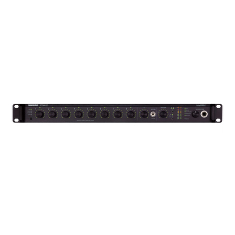
Front Panel
①Channel Mode Selection
PressthebuttontoselectthefunctionofthechannelknobsandmonitorLEDrings.SeetheAudioSignalAdjustmentsec-
tion for details on each mode.
②Assignable Channel Knob
Adjusts settings and status for each input:
Rotate: Adjusts a setting.
Momentary Press: Solos the channel to the headphone output.
Press and Hold: Mutes the audio or bypasses the EQ setting.
③Monitor LED Ring
13 LED segments display gain setting, input signal meter, IntelliMix gain meter, channel solo, or EQ setting.
④Channel Status LED
LED Channel Status
Off Channel is closed (attenuated in the automix).
Green Channel is open (selected in the automix).
Amber Channel EQ is bypassed.
Flicker Red Signal is clipping. Set the channel to a lower input gain level.
Solid Red Channel is muted.
⑤Auxiliary Input Jack (1/8")

Shure Incorporated
7/59
Unbalanced aux input sums left and right channels to mono. Front and back panel aux inputs are summed to a mono signal
and routed without automixing to the mix outputs.
⑥Master Output Knob
Adjusts settings and status of the mix outputs. See Front Panel Modes for details.
Rotate: Adjusts output gain or limiter threshold.
Momentary Press: Overrides a soloed channel to return the mix to the headphone output.
Press and Hold: Mutes the audio or bypasses the limiter.
⑦Master LED Ring
Displaysgainsettingorlimiterthreshold.AsingleLEDrepresentseachmixerwhentheyarebothselectedbutsettodiffer-
ent levels.
⑧Master Mode Selection
Selects the function (gain or limiter) of the master knob and LED ring.
⑨Mix Select Button
Selects Mix A, Mix B, or both for adjustment with the master knob and monitoring on the LED ring and headphone output.
Note: When both Mix A and Mix B are selected, the headphone output only monitors Mix A.
⑩Mix Status Indicator
LED Mix Status
Green Mix is selected for adjustment and listening on the headphone output.
Amber Limiter is bypassed.
Red Mix is muted.
⑪Audio Output Meters
Monitor the output signal level and limiter threshold for mix A and B.
⑫LIM (Limiter) LEDs
Illuminate amber when the audio levels exceed the limiter threshold.
⑬System Status Indicators
The LEDs illuminate to indicate system settings:
LED Color Status
power Green Unit is powered on.
ethernet Green Unit is connected to a network.
network audio Green All connected receive channels are OK (receiving digital audio
as expected).

Shure Incorporated
8/59
LED Color Status
Flashing Green
Oneormoreconnectedreceivechannelsexperiencingasub-
scriptionerrororisunresolved(transmittingdeviceisoff,dis-
connected, renamed or has incorrect network setting).
Red Clock synchronization problem.
Off Noreceivechannelsconnected(routinghasnotbeenestab-
lished).
automix link
Green Two or more mixers are connected in a link group.
Flashing Green Link Group is configuring.
Off Mixer is in standalone mode.
dual mixer
Green Mixer is set to Dual Mixer operation.
Off Mixer is set to Single Mixer operation.
lockout
Red Front panel controls are locked.
Flashing Red An adjustment is attempted in lockout mode.
⑭Headphone Volume Knob
Adjust the volume of the headphone output.
⑮Headphone Output Jack (1/4 in.)
Monitor a mix or a soloed channel.
Rear Panel
①Power Switch
Turns the unit on or off.

Shure Incorporated
9/59
②AC Power Jack
Supplies AC power to the mixer when plugged into a power source.
③Mix A and Mix B Outputs
Active balanced outputs connect to amplifiers, DSP, mixer, or recording device.
④Auxiliary Input Jack
Unbalanced aux input sums left and right channels to mono. Front and back panel aux inputs are summed to a mono signal
and routed without automixing to the mix outputs.
⑤ Channel Inputs 1–8
Active-balanced microphone- or line-level inputs.
Block Connectors
Audio +
Audio−
Audio ground
gate
Logic gate out
mute
Logic mute in
ovrd
Logic override in
gnd
Logic ground
DB25 Connector
Pins
Audio plus, audio negative and audio ground. See Specifications for details.
⑥ Direct Outputs 1–8
Each channel has a dedicated, impedance-balanced direct output on the back panel that can be selected from one of five
stages in the signal path. See Configuring the Inputs and Outputs for details on direct output routing.

Shure Incorporated
10/59
◦
◦
⑦ Chassis Ground Screw 1–8
Provides an optional connection for microphone shield wire to chassis ground.
⑧IntelliMix Select Buttons
Scrolls through IntelliMix presets for each mix output. When dual mixer is off, the A button sets the mode for both Mix A and
Mix B.
⑨Dual Mixer Button
Sets the SCM820 as a dual mixer, indicated by the green LED.
⑩Channel Select Button and Display
Presstoselectasinglechannel(1–8)orallchannels(A) when changing input gain or phantom power.
When all channels are selected (A), Input Level and Phantom Power LED indicators only illuminate if all channels have the
same setting.
L is displayed when the mixer is in lockout mode.
⑪Input Gain Selection and LED Indicator
Sets the analog input gain level for the selected channel(s), illuminating the green LED. All LEDs are off when the channel's
audio source is set to Network from the GUI.
⑫Phantom Power Button and LED Indicator
Supplies 48 VDC phantom power to the selected channel(s), illuminating the green LED. Phantom Power is disabled in the
line (+0dB) gain setting.
⑬Auto Link Button and LED Indicator
EnablesnetworkedSCM820-DANmixerstoautomaticallyformalinkgroup.LinkGroupsenablealargeraudiomixbyin-
corporating inputs from two or more mixers. See Link Groups for more details.
⑭Lockout Button and LED Indicator
Hold for five seconds to disable front and back panel controls. The front panel lockoutLEDilluminatesred(flashingreddur-
ing an adjustment attempt) and the back panel channel display shows L.
⑮Reset Button
Press and hold for five seconds to reboot the mixer with default system settings restored.
⑯Network Ports
RJ-45 jacks for network connection.
⑰Network Status LED (Green)
Off = no network link
On = network link established
Flashing = network link active
⑱Network Speed LED (Amber)

Shure Incorporated
11/59
◦
◦
◦
◦
◦
◦
SCM820:
Off = 10 Mbps
On = 100 Mbps
SCM820-DAN:
Off = 10/100 Mbps
On = 1 Gbps
Signal Path Diagram
The following diagram shows the audio signal path and the routing options for several features (default configuration shown).
Use the web application to change the configuration.
Audio Source Selection
Analog
Network
Input Meter Mode
Pre-Fader
Post-Fader
Headphone Mode (Channel)
Pre-EQ
Post-Fader

Shure Incorporated
12/59
◦
◦
◦
◦
◦
◦
◦
Mute Control
Pre-IntelliMix
Post-IntelliMix
Direct Output Selection
Pre-EQ
Post-EQ
Post-Fader
IntelliMix
IntelliMix NOMA
Operating the Mixer
Front Panel Modes
Channel Inputs
The channel knobs operate in five modes for different types of input signal adjustment and display. Use the front panel mode
selection button to select from the following modes.
Channel Gain (gain)
Adjust gain within a 128 dB range while displaying the gain setting on the LED ring. Unity
gain is at the 9th LED.
Low Cut (low cut)
Adjust the frequency of the low cut filter (6 dB/octave from 25 to 320 Hz). Use to remove
low-frequency noise such as table vibrations or air-conditioning rumble.
High Shelf (hi shelf)
Adjust the high shelf boost or cut (± 12 dB at 5 kHz). Use to add presence to muddy vocals,
temper sibilant vocals, or enhance the sound of off-axis lavalier microphones.
Input Signal Meter (ch. me
ter)
LEDs display the input signal level in real-time. Channel gain is adjustable in this mode, and
will momentarily display channel gain setting during adjustments.
IntelliMix Gain Meter (gain
and ch. meter)LEDs display the IntelliMix attenuation applied in realtime. Channel gain is adjustable in this
mode, displaying the setting on the LEDs during adjustments.

Shure Incorporated
13/59
Mix Outputs
The mix output knob operates in two modes to control the mix output. Use the master function button to select one of two
modes.
Output Gain (gain)
Rotate to adjust the output gain of the selected mix. The output signal level is displayed on
the meters.
Limiter Threshold (limiter)
Rotatetoadjustthelimiterthresholdofthemix(−2to−50dBFS).Thelimiterthresholdlevel
is displayed on the meters.
Mode Selector
Audio Mute and Bypass
Mute Channel Input
Press and hold the input channel knob while in gain or ch. meter mode. The channel status LED turns red.
Mute Mix Output
Press and hold the MASTER knob while in gain mode. The mix status LED turns red.
Bypass Input EQ
Press and hold the input channel knob while in low cut or hi shelf mode. The channel status LED turns amber.
Bypass Output Limiter
Press and hold the MASTER knob while in limiter mode. The mix status LED turns amber.
Monitoring
Headphone Output

Shure Incorporated
14/59
Use the front panel headphone jack for monitoring audio. By default, the headphones monitor the mix pre-fader/post-EQ
(change to post-fader/post-limiter from GUI > Preferences Tab).
Solo to Headphones
A channel can be soloed to the headphone jack.
Solo Channel
Press a channel knob to solo that channel to the headphones. The other LED rings dim to highlight the soloed channel.
Exit Solo
Press the soloed channel knob or press the Master knob to return the mix to the headphones.
Input Meters
The front panel channel meters can be set to display real-time signal information. Use the front panel mode selection button to
scroll to the desired mode:
Input Signal Level
The channel meter mode (ch. meter) displays real-time audio input signal level for each channel.
IntelliMix Gain
The IntelliMix meter mode (gain and ch. meterilluminated)displaysIntelliMixgainoperationinreal-timeacrossthechan-
nel LEDs. Channels that gate open will display more gain than channels that are closed (attenuated) in the mix.
Output Meters
The output meters indicate the level of each mix before the digital-to-analog conversion. By default, the meter displays average
andpeakaudiolevels.Itisgoodpracticetouse−18dBFSontheSCM820meterasanapproximationof0VUonananalog
meter.
LED Description Signal Level (dBFS)
Red (7) Clip 0 to -6
Yellow (6)
Normal peaks
-6 to -9
Yellow (5) -9 to -18

Shure Incorporated
15/59
•
•
•
•
•
•
•
•
LED Description Signal Level (dBFS)
Green (4)
Signal Present
-18 to -24
Green (3) -24 to -36
Green (2) -36 to -48
Green (1) -48 to -60
Changing the Metering Type
Go to the Preferences tab of the GUI to change the following metering options:
Meter Type: Change the input and output meters from displaying VU + Peak (default) to VU or Peak.
IntelliMixGainMetering:TheInputtaboftheGUIcandisplayinputsignallevel(default)orIntelliMixgainmeteringinreal-
time.
SCM820 Application
The SCM820 application enables comprehensive control of the mixer. The application is accessible from any computer. Use
the application for the following functions:
Manage mixers from a remote location.
Customize IntelliMix parameters.
Form large automixes with custom link groups.
Assign the direct outputs in the signal path.
Configure redundant or split networks.
Set up Shure Digital Feedback Reducer (DFR) for up to two channels in each mixer.

Shure Incorporated
16/59
•
•
•
1.
2.
1.
2.
System Requirements
Operate the control software on computers and mobile devices that meet the following criteria:
Windows 10
Microflex Wireless (MXW) application (used for Shure network configuration)
Dante Controller (used for network configuration)
Accessing the SCM820 application
Follow these steps to install the software and access the SCM820 app:
①Get the Shure SCM820 application and the Shure Microflex Wireless (MXW) application
Get these applications to see devices on the network and open the control interface. Download the software from
www.shure.com/software.
②Connect the network
Ensure that the computer and the mixer are on the same network.
③Launch the Microflex Wireless (MXW) application
The application displays all Shure devices on the network.
Locate your SCM820 device on the network
Copy the IP address of your device
④Access the SCM820 application
Paste the IP or DNS address of the device to the SCM820 application
Press Connect
⑤The SCM820 application opens

Shure Incorporated
17/59
•
•
•
•
•
•
•
•
Accessing network settings
Use MXW application to
specify network type
Network type
Static
DHCP
Use Dante Controller to
change
Network mode
Dante network control
Audio settings
Installation
Power
Connect the unit to AC power using the supplied IEC cable. Turn on the power switch.
Rackmounting
Rackmount the mixer using the screws and washers supplied in the Hardware Kit. Follow these general best practices when
rackmounting equipment:
Ambient temperature of the rack should not exceed specified operating temperature range of the device.
Keep fan inlet and side air vents clear from obstructions and provide adequate space for airflow within the rack.
When possible, provide 1 RU of empty space between each device.

Shure Incorporated
18/59
◦
◦
◦
◦
◦
◦
◦
◦
◦
Typical Audio Connections
①Channel Inputs
Microphones
Insert send from a mixer
Dante network audio
②Aux Inputs
Aux-level sound sources:
MP3 player
Computer headphone output
CD player
③Mix Outputs
Amplifier
Powered speakers
Mixer channel inputs

Shure Incorporated
19/59
◦
◦
◦
•
•
•
•
•
•
•
④Direct Outputs
Insert returns to a mixer
Recording device
Mixer channel inputs
Configuring the Inputs and Outputs
Unless where noted, configurations can be made from the hardware or from the GUI.
Inputs
①Select the Audio Source
(GUI only)
Analog (default): Audio is from a microphone or line-level audio source connected to a
channel input on the mixer back panel.
Network: Audio is from the Dante digital audio network. Go to the Inputs tab of the GUI
to select Network audio for each desired channel. Dante Controller software is required
to properly route audio to the channel inputs.
②Select the Input Gain
Select the analog input gain for each channel. No gain is applied for analog line-level or
when the audio source is set to Network.
Mic (+46dB): For less sensitive microphones, such as dynamics.
Mic (+26dB): For loud talkers or sensitive microphones such as condensers.
Line (+0dB): For line-level sources such as mixer inserts.
③Supply Phantom Power Supply 48 V phantom power to the channel when using condenser microphones. (Phantom
power is disabled when Input gain is set to Line.)
④Adjust Channel EQ
Adjustthehigh-andlow-frequencyequalizationtoimproveintelligibilityandreduceunde-
sired noise:
Low Cut: Ideal for attenuating low-frequency vibration caused by table vibrations or air-
conditioning rumble. Adjust the frequency of the 12 dB/octave filter from 25 - 320 Hz.
HighShelf:Fortemperingsibilantspeechorenhancingthesoundofoff-axismicro-
phones.Usethistoboostorcutthesignalby12dBat5kHzwithaslopof12dB/oc-
tave.

Shure Incorporated
20/59
Hardware Adjustments
Channel Selection
To adjust the Input Gain or Phantom Power, press the CH to scroll to Afor All channels, or select a single channel.
Channel Mode Selector
Select a mode to adjust gain or EQ settings.
Mix Mode Selector
Select a mode to adjust output level or limiter threshold.
Other manuals for SCM820 Digital IntelliMix
5
Table of contents
Other Shure Mixer manuals