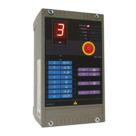
SIAD ESA ESTRO Series User manual

E7014
Tel. +39 035 6227411 - Fax +39 035 6227499
Limited Company - Share Capital Euro 153.111,00 paid up
V.A.T. number: IT 00793030164
Fiscal number: 03428410157
Registered Office
Via Canovine, 2/4 - I-24126 Bergamo, Italy
Registro Imprese di Bergamo n°03428410157
R.E.A. n°173124
Export: BG0061150
1
ESA S.r.l.
Via E. Fermi, 40
I-24035 Curno (BG), Italy
MICROPROCESSOR OPERATED BURNER CONTROL DEVICE
ESA ESTRO SERIE
INTRODUCTION
ESA ESTRO is a microprocessor operated device, designed to
control gas and oil fired burners, discontinuously operated.
This device warrants the safe operation of combustion unit at
one or two stages (pilot and main burners), it controls the air
flow rate and allows the detection of flame presence through
ionization (electrodes) or UV radiation (UV-scan).
ESA ESTRO is equipped for serial communication, allowing a
remote burner control and operation. The thermal resistant
case of ESA ESTRO allows its installation on burner proximity,
provided the environment temperature will remain below 60°C.
APPLICATIONS
-One or two stages (pilot and main) discontinuous burners;
-Flame detection by means of rod, unirod and UV scan (also
combined);
-Packaged burners managing a complete ignition cycle
(blower, air damper, air pressure switch);
-Burners with air valve control for furnace purging, burner
ignition and thermoregulation (heating/cooling) via external
regulation device;
-Combustion plant with burners controller via digital signal or
ECS serial communication;
-Customized burners operation through programmable
expansion cards.
FEATURES
MAIN
• Supply voltage: 115 Vac o 230 Vac +10÷-15%
• Frequency: 45÷65 Hz
• Power Supply Mode phase-neutral, non suitable for phase-
phase
• Neutral Type suitable for ground as well as non
ground neutral connection
• Power consumption (without outlets): 4 VA max
• Operating temperature: 0÷60 °C
• Storage temperature: -20÷80 °C
• Protection class: IP54 (when wiring, use adequate
connectors)
• Mounting position: any
• Installation Environment not suitable for ATEX classified area
and corrosive area
• Case Thermosetting with glass fiber
• Size 200×120×93 mm
• Weight 1.300 g

E7014
2
• Approvals according EN298 and EN230 BOOLXN programmable
INPUT AND OUTPUT CONNECTIONS
• Flame Detection Probe voltage: 300 Vac max
• Minimum ionization current: 3 µA
• Flame Probe current limitation: 1 mA
• Flame signal display: 0 ÷ 90 µA
• Flame Probe Type electrode or UV scan model ESA UV-2
• Rod or UV scan probe line length < 30 m
• High Voltage ignition transformer line length 2 m max
• Insulation among probe conductors: > 50 MΩ(double-insulation or double-
protection cables)
• Digital input signal voltage same as supply voltage
• Digital input power consumption max 5mA
• Filter for lock/reset input RC 100Ω- 0,47 µF - 250 Vac
• Output signal voltage same as supply voltage
• Current per each output signal 1,5 A Max
• Current per output signals (total) 4 A per 10 sec. / min.
• Load protection fuse: 4 A fast
• Device protection fuse: 1 A non replaceable
• Supply Voltage expansion card EXP-2 and EXP-4 24 Vac, 115 Vac, 230 Vac
• Power Absorption expansion card EXP-2 and EXP-4 5 mA max
• Output signal voltage expansion card EXP-2 and EXP-4 same as supply voltage
• Maximum Output current expansion card EXP-2 and EXP-4 4 A (non protected by inner fuse)
PARAMETERS
• Pre-purge time* 0 ÷ 255 s
• First safety time* 1 ÷ 25 s
• Main burner stabilization time*: 0 ÷ 25 s
• Reaction time*: 1 ÷ 20 s
• Post-purge time *: 0 ÷ 255 s
• Accepted unlocking: 5 max in 15 min,
• Auto shutoff (can be inhibited) *: 1 minimum in 24 hours
• Action at missing flame signal Programmable
• First gas stage actions Programmable
• Air valve operation Programmable
* These parameters must comply the norms and directives related to the industrial process wherein ESA
ESTRO is adopted as burner control device

E7014
3
DESCRIPTION
ESA ESTRO is a device based on microprocessor technology, provided with input and output
connections, suitable to control discontinuous burners operation (at least one burner shutoff each 24
hours). The instrument is available in four different releases.
• ESA ESTRO- A: single stage burner (one gas valve) with air valve operation control
The configuration software allows the proper definition of the air valve operation.
• ESA ESTRO- B: two stages burners (1
st
pilot, 2
nd
main).
The configuration software sets the operation of the pilot burner (1
st
stage gas) in continuous or
discontinuous mode.
• ESA ESTRO-C: single stage burner (one gas valve) with output signal for burner “ON” indication.
ESA
ESTRO
A
IGNITION
TRANSFORMER
DIGITAL INPUT
GAS VALVE
REMOTE
CONTROL
AIR VALVE
FLAME SIGNAL
ALARM
ESA
ESTRO
B
IGNITION
TRANSFORMER
DIGITAL INPUT
1ST STAGE
GAS VALVE
REMOTE
CONTROL 2ND STAGE
GAS VALVE
FLAME SIGNAL
ALARM
ESA
ESTRO
C
IGNITION
TRANSFORMER
DIGITAL INPUT
GAS VALVE
REMOTE
CONTROL
BURNER ON
FLAME SIGNAL
ALARM

E7014
4
• ESA ESTRO-Q: single stage burner (one gas valve) dedicated to combustion unit controlled via serial
communication modes.
Moreover the release ESTRO-A, ESTRO-B and ESTRO-C allow to set an output signal for burner
lockout and a digital input signal. The input signal availability is mandatory (according EN746-2) for high
temperature applications in order to accomplish the dedicated function.
All ESA ESTRO releases are currently provided with ECS serial communication interface, in order to
allow the remote burner control through ECS or Modbus-RTU protocols.
The serial communication allows the complete control of the combustion unit: burner ignition and shutoff,
first and second gas stages operation, air valve control, burner supervision and flame detection.
ESA
ESTRO
Q
IGNITION
TRANSFORMER
GAS VALVE
REMOTE
CONTROL
FLAME SIGNAL
FIELDBUS
P
L
C
GAS
ESTRO-B
25
6
3
4
+1 A-
8 97 B
10
GAS 2
1
GAS
ESTRO-A
N
N
5
6
3
4
+
+
L
L
1
-
-
8 97 2
10
AIR A
1
GAS
ESTRO-C
2
5
6
3
4
+
1
A
-
8
9
7
B
10
1
GAS
ESTRO-Q
N
+
-
V
N
+
L
*
-
N
F
T
*
G
1
ECS BUS
POWER LINE
POWER
SUPPLY
SAFETY
LIMITS

E7014
5
ESA
EXP-2
AIR VALVE OR
BLOWER
THERMOSTAT
OPEN AIR
DAMPER
AIR PRESSURE
SWITCH
CLOSE AIR
DAMPER
DAMPER OPEN
POSITION SWITCH
DAMPER CLOSE
POSITION SWITCH REGOLATION
ENABLED
ESA
EXP-3
PROFIBUS-DP
DEVICE-NET
ETHERNET
On its front panel ESA ESTRO mounts a programmable push button, an alphanumeric display of status
indication, a bargraph flame signal indicator and the infrared communication port for “on field”
instrument’s configuration.
Dedicated configuration software allows the definition of several operation parameters, according
process requirements, like the control of the air valve, the lockout output signal, the scheduled time for
each phase (according the ranges defined by the reference norms).
ESA ESTRO is provided with a solid case in thermosetting composition, ready to seat the ignition
transformer and the output wires for external connections.
Dedicated Expansion cards can be connected to each release of ESA ESTRO, in order to implement
additional features or specific serial communication modes. The installation of an expansion card into the
ESA ESTRO device obliges to install the ignition transformer into an external thermosetting case named
ESA TRAFO.
Hereinafter the expansion cards available are described according their main features:
• EXP-2: dedicated to “package burners” controls the air valve or blower start, verifies the air pressure
switch signal and operates the initial purging and burner ignition procedures.
Expansion card EXP-2 could be also adopted to simply operate the air valve (for device releases
different from ESTRO–A).
• EXP-3: developed to implement serial communication with the most common fieldbus standards.
For detailed information please refer to the technical bulletin E7015.

E7014
6
• EXP-4: provided with four digital inputs, four digital outputs, one analog input, one analog output and a
serial interface in order to allow remote card control.
For detailed information please refer to the technical bulletin E7016.
CERTIFICATION – CONFORMITY
o
ESA ESTRO comply the EN298 as certificate I7800 issued by notify body 0694.
ESA ESTRO is in accordance to European Union directives: Directive on appliances burning
gaseous fuels 90/396/CEE, Machine directive 2006/42/CEE, Low voltage directive
2006/95/CEE, Electromagnetic Immunity 89/336/CEE, in conjunction with EN298, EN230
and EN746-2.
ESA
EXP-4
DIGITAL
OUTPUT 1
DIGITAL
OUTPUT 2
DIGITAL
OUTPUT 3
DIGITAL
OUTPUT 4
DIGITAL
INPUT 1
DIGITAL
INPUT 2
DIGITAL
INPUT 3
DIGITAL
INPUT 4
ANALOGIC
INPUT 4
ANALOGIC
OUTPUT 4

E7014
7
ALPHANUMERIC VISUALIZATION AND PUSHBUTTON
DISPLAY
ESA ESTRO displays through several symbols the status of the burner control device. Fixed characters
indicate the normal operating conditions or some instruments’ failures that cannot be restored, while
lockout conditions or restorable failures are indicated with blinking symbols.
Normal operation stages
DISPLAY INDICATION DESCRIPTION
FIXED
Self-diagnosis phase; the equipment controls the efficiency of its
components. It is shown every time the equipment is powered or when
the burner is re-started (it lasts near 2 sec).
BLINKING
Manual lockout. The equipment is waiting for the operator’s reset
command via the local, remote or serial button. It is shown every time
the equipment is powered in case the parameter “Power on” is
configured as “Stand-by".
FIXED
Burner shutoff caused by the temp controller. The instrument leads the
burner in “off” mode, close the air valve and disables others exits.
FIXED
Air pressure switch signal waiting phase after air valve activation (or
blower start), or burner shutoff during operation in case of incorrect air
pressure signal. It is shown with expansion cards in case the parameter
“Air switch” is configured as “Waiting”.
FIXED
Initial purging: air valve is opening and the maximum opening position
is not yet reached (position switch). It is shown with expansion cards in
case the parameter “Air damper” is configured as “Local o Remote".
FIXED
Purge or waiting time before burner ignition. For applications with
controlled cooling slope, only the air valve is open in this phase. At this
stage the device verifies the presence of illegal flames and eventually
generates a shutoff reaction.
FIXED
Initial purging: air valve is closing and the minimum opening position is
not yet reached (position switch) to warrants ignition at minimum firing
rate. It is shown with expansion cards in case the parameter “Air
damper” is configured as “Local o Remote".
FIXED
Burner ignition at 1
st
stage gas, it lasts as the first safety time. The
device activates the ignition transformer and the 1st stage gas valve,
then deactivates the transformer and verifies the flame presence.
FIXED
Check of flame stability at 1
st
stage gas, followed by the flame’s
amplifier control. This phase is shown also in case of shutoff of the 2
nd
stage burner.
FIXED
Normal operation stage for ESTRO-A, ESTRO-C and ESTRO-Q. For
ESA ESTRO-B release it signals the 2
nd
stage gas burner and it lasts
as the second safety time. In this phase both 1
st
and 2
nd
gas valve are
activated. This is the normal operation stage also for ESA ESTRO-B in
case the parameter “1st stage gas” is configured as “Intermittent”.
FIXED
Normal operation stage for ESA ESTRO-B with only 2
nd
stage gas
burner activated. The device closes the 1st stage gas valve. This phase
is present only in case the parameter “1st stage gas” is configured as
“Interrupted”.

E7014
8
FIXED
Normal operation stage with air valve activated. In case the parameter
“Air switch” is configured as “Lockout or Waiting" the device waits the
signal of the air pressure before to show this stage, while when
configured as “Disable” the switch to this stage coincides with the air
valve opening. This phase is present only in case the parameter “Air
flow control type” is configured as “Discontinue or Pulse”.
FIXED
The device verifies the flame’s complete extinguishment in maximum
20 sec. after burner shutoff; otherwise a lockout signal for illegal flame
presence is activated.
FIXED POINT
Furnace purging with air (or waiting phase) after burner shutoff.
During this phase the device doesn’t accept any command and shows
the symbol referred to the phase or block that activated the shutoff
procedure.
FIXED
Burner shutoff phase requested by temp. controller. The device hold the
burner in “OFF” mode waiting for a new start signal, keep closed the air
valve and deactivate the output signals.
BLINKING POINT
High Temperature Operation mode active. During this phase the device
shows the fixed code related to the active phase.
Lockouts or failures
DISPLAY INDICATION DESCRIPTION
BLINKING
Manual burner shutoff, executed through local or remote push button
during the normal operation stage. The device holds the burner in “OFF”
mode waiting for a new start signal.
BLINKING
Lockout due to a signal of illegal flame presence, before the burner
ignition or after burner shutoff. The causes could be related to the
detection device (failure) or to a fuel gas leaks through the interception
solenoid valves.
BLINKING
Lockout due to a failed burner ignition attempt at 1
st
stage gas. The
causes could be related to the ignition devices (electrode and/or
transformer), to wrong air/fuel ratio gases, or to the flame detection
device (probe or wiring failure). On the first mentioned case the burner
is not ignited, vice versa on the second the flame is present but ESA
ESTRO is unable to detect it.
BLINKING
Lockout due to a missing flame presence signal during the normal
operation stage. The causes could be related to a wrong air/fuel ratio
(too fast flows variation or ratios out of the flame stability range), or to
the flame detection device (probe position or cleanliness).
BLINKING
Lockout due to the extended absence of serial signals from the remote
controller, for a period of time longer than the parameter set as
“Communication timeout”.
The causes could be related to wrong connections or to the serial
communication management.
FIXED
Malfunction due to the presence of the air pressure switch signal before
the blower activation. The causes could be related to a wrong pressure
switch wiring or in its failure.

E7014
9
BLINKING
Lockouts due to a malfunction of the inner circuit for air pressure switch.
In case after a reset procedure attempt the indication is still present, the
device has to be sent back to the manufacturer for inspection
BLINKING
Lockout due to the missing signal from the air pressure switch during
normal operation stage. The causes could be related to a pressure
switch failure or to some problems related to the air flow (i.e. filter
obstruction).
BLINKING
Lockout due to the presence of the signal of air valve complete opening
(“maximum” position switch) before the device allowed the valve
opening. The causes could be related to a wrong electrical wiring or to a
wrong air valve switches regulation.
BLINKING
Lockout due to the presence of the signal of air valve complete closure
(“minimum” position switch) before the device allowed the valve closure.
The causes could be related to a wrong electrical wiring or to a wrong
air valve switches regulation.
BLINKING
Lockout due to the missing closure of the air valve after the initial
purging phase. The device waits for a maximum of 150 sec. from the
closing command the signal generated by the “minimum” valve position
switch. The causes could be related to a wrong electrical wiring or to a
wrong air valve switches regulation.
BLINKING
Lockout due to the missing electrical absorption from the ignition
devices connected to ESA ESTRO ( ignition transformer or solenoid
valves). The causes could be related to an electrical connection
interruption, to the failure of one of the ignition devices or to a protection
fuse failure.
BLINKING
Lockout due to a malfunction of the flame detection probe. The causes
could be related: to a probe failure, to a short circuit between the probe
or his connection to ground (burner body), to the reverse connection of
UV tube ESA UV-2, to a wrong or connection of the ground at the
device, or to strong current on the furnace ground (welding in progress).
BLINKING
Lockout due to a malfunction of the inner flame amplifier. In case after a
reset procedure attempt the indication is still present, the device has to
be sent back to the manufacturer for inspection.
BLINKING
Lockout due to a malfunction of the inner circuit related to the temp.
controller. In case after a reset procedure attempt the indication is still
present, the device has to be sent back to the manufacturer for
inspection.
BLINKING
Lockout due to an error of the inner memory of the device. The failure
could be temporary or definitive and the causes could be related to
wrong or inadequate electrical connections of the device. In case after a
reset procedure attempt the indication is still present, the device has to
be sent back to the manufacturer for inspection.
BLINKING
Lockout due to the missing communication with the installed expansion
card (EXP-2 or EXP-4). The causes could be related to a wrong
configuration or a failure of the expansion card. It is required to verify
the card configuration; in case after a reset procedure attempt the
indication is still present, the device has to be sent back to the
manufacturer for inspection.

E7014
10
BLINKING
Lockout due to a malfunction of the inner relays. In case after a reset
procedure attempt the indication is still present, the device has to be
sent back to the manufacturer for inspection.
FIXED
Malfunction of to the local push button or of the digital input signal (for
remote operation): they are fixed on the “pressed” position during the
self-diagnosis phase. The causes could be related to the connection of
the remote signal, to the absence of RC filter, or to a malfunction of the
push button. In order to reset the alarm cut off the electrical supply to
the device for few seconds.
FIXED
Malfunction due to corruption of the inner memory of the device or to a
failure of the safety circuit. The failure could be temporary or definitive
and the causes could be related to wrong or inadequate electrical
connections of the device. In order to reset the alarm cut off the
electrical supply to the device for few seconds. In case after a reset
procedure attempt the indication is still present, the device has to be
sent back to the manufacturer for inspection.
FIXED
Malfunction due to short-circuit of the inner safety circuit relays. In order
to reset the alarm cut off the electrical supply to the device for few
seconds. In case after a reset procedure attempt the indication is still
present, the device has to be sent back to the manufacturer for
inspection.
FIXED
Malfunction due to short-circuit of the microprocessors’ pins. In order to
reset the alarm cut off the electrical supply to the device for few
seconds. In case after a reset procedure attempt the indication is still
present, the device has to be sent back to the manufacturer for
inspection.
FIXED
Malfunction due to a jump code program. The failure could be
temporary or definitive and the causes could be related to wrong or
inadequate electrical connections of the device. In order to reset the
alarm cut off the electrical supply to the device for few seconds. In case
after a reset procedure attempt the indication is still present, the device
has to be sent back to the manufacturer for inspection.
DISPLAY AND
BARGRAPH
BLINKING
Malfunction due to an excessively high ambient temperature. In these
conditions the device turn on and off continuously, showing only the
self-diagnosis initial procedure.
Configuration
DISPLAY INDICATION DESCRIPTION
FIXED
Configuration phase of the device via serial input (based on the
dedicated software). During this phase the execution of any other
operation is not allowed.
FIXED
Configuration phase of the device via infrared input (based on the
dedicated software). During this phase the execution of any other
operation is not allowed.
BARGRAPH
ESA ESTRO is equipped with a 5 LED bargraph to shows the value of flame detected signal in a range
from 0µA to 90µA. In case of detection currents higher than 90µA all the LED remain lighted.

E7014
11
The flame detection signals generated via electrode (ionization) are normally lower than those generated
via UV scanner; nevertheless in both cases the bargraph shows the stability of the flame signal and
therefore the reliability of the burner.
LOCAL PUSH BUTTON
ESA ESTRO allows the configuration of the push button operation according its application’s
requirement (see chapter Configuration). The push button may execute the manual operations of
unlocking and shutoff, only manual unlocking, only manual shutoff and it can be disabled in case of
serial communication modes.
According its function the button action can be different:
-unlocking: the push button has to be pressed for 1 to 3 sec. and when released it executes the
unlocking of ESA ESTRO;
-manual shutoff: the push button executes immediately the ESA ESTRO stop when pressed.

E7014
12
ACTIONS
ESA ESTRO is a programmable device designed to control gas and oil fired burners in different modes
according the process parameters set (see chapter Configuration).
Hereinafter its main actions are described.
BURNER IGNITION CYCLE
The scheme describes the burner ignition cycle execution when ESA ESTRO is provided with EXP-2
expansion card.

E7014
13
BURNER IGNITION CYCLE
The scheme describes the burner ignition cycle execution when ESA ESTRO is in standard version,
without the EXP-2 expansion card.
OPERATION AT POWER SUPPLY
The followings scheme describe the ESA ESTRO actions at power supply, according the configured
parameter “Cycle start” if set as “Autostart” or as “Standby”.
Autostart

E7014
14
Standby
ILLEGAL FLAME PRESENCE
The scheme describes the ESA ESTRO actions in case of illegal flame signal before burner ignition or
after shutoff.

E7014
15
FAILED IGNITION
The scheme describes the actions in case of failed ignition attempt at 1
st
gas stage.
FLAME SIGNAL LOST
The scheme describes the actions in case of flame signal lost during the normal operation stage and in
case of setting of the parameter “Flame loss” as “Lockout”.
115

E7014
16
CONFIGURATION: SETTING PARAMETERS
The configuration defines the operation mode of ESA ESTRO according the combustion plant needs.
In compliance with the reference norm, some of the parameters are set and locked at the device’s
production facility, while others can be modified by the user with dedicated tools.
The setting parameters variation can be done only if ESA ESTRO is in “manual stop” phase and can be
done via a portable programming device (infrared) to modify the serial communication parameters (i.e.
device IP address) or through a specific software via serial communication interface (ECS driver) to
modify every unlocked parameter.
The programming software, moreover, allows the user to lock some additional setting parameters in
case of needs for safety reasons.
The configuration via ECS serial interface is allowed only for one device at the time and it is required its
disconnection from the field network and the direct connection to the programming PC card interface.
Unlocked setting parameters
PARAMETER VALUE DESCRIPTION
Address
Segment 0 ÷ 9 and
A ÷ Z capital
“Address Node” identifies the device for serial communication.
Adopting ECS protocol defines the zone or belonging group. Adopting
Modbus-RTU defines the first char of the address (0÷F per 0÷16)
Address Node 0 ÷ 9 and
A ÷ Z capital
“Address Segment” identifies the device for serial communication.
Adopting ECS protocol defoines the device unity inside a zone or
belonging group. Adopting Modbus-RTU defines the second char of
the address (0÷9)
Baudrate /
protocol
4800 ÷ 38400
ECS Communication speed with ECS protocol (4800, 9600, 19200 and
38400 Bit/s)
4800 ÷ 38400
ModbusRTU 1
Velocità di comunicazione (4800, 9600, 19200 e 38400 Bit/s) con
protocollo Modbus RTU (1 bit di stop).
4800 ÷ 38400
ModbusRTU 2
Communication speed with Modbus RTU protocol (4800, 9600, 19200
and 38400 Bit/s)
Communication
timeout 0 ÷ 480
Time limit for serial communication signal absence, set in ten steps
from 0 to 480 sec., the device signal a “Com-timeout” alarm in case
this time is exceeded. Setting at “0” sec. this parameter disable the
com-timeout alarm when the serial communication is not adopted.
Prepurge time 0 ÷ 255 Time of furnace chamber purging or waiting before burner ignition. In
case of applications with air valve control, the countdown starts when
the position switch signals the maximum valve opening.
Regulation
delay time –
2°safety time 0 ÷ 25
Waiting time after the flame stability check at 1st stage gas; concluded
this phase the air valve opening is allowed (for ESTRO-A and
expansions).
For ESA ESTRO-B this time refers the second safety time (ignition
2°gas stage), therefore the setting parameter is lo cked. Moreover
concluded this time the 1
st
stage gas is turned off in case of
discontinuous setting.

E7014
17
Postpurge time 0 ÷ 255
Time of furnace chamber purging after shutoff or waiting before next
burner ignition (air valve opening in case of applications with air valve
control). During this phase the device doesn’t accept any external
command.
The function “Postpurge flex” defines the minimum interval of time
between two ignition attempts.
Cycle start
Autostart The ignition cycle starts automatically at power supply (except for
cases of burner’s lockout before shutoff). This type of setting is
suitable for burner control via the device power supply.
Standby The ignition cycle doesn’t start automatically at power supply (waiting
for local or remote command). This type of setting is suitable for
burner control via the serial communication.
1°stage gas
outlet type
Intermittent
The 1
st
stage gas remains ON also during the 2
nd
stage gas until the
simultaneous shutoff of both valves.
This setting is allowed only for ESTRO-B release, the parameter is
locked for ESTRO-A, ESTRO-C and ESTRO-Q (only 1
st
stage gas.)
Interrupted
The 1
st
stage gas is turned OFF during the 2
nd
stage gas when the
second safety time or “Regulation delay time” (2
nd
stage stabilization)
is exceeded. This setting is allowed only for ESTRO-B release, the
parameter is locked for ESTRO-A, ESTRO-C and ESTRO-Q (only 1
st
stage gas.)
Daily shut off Inhibited
The device doesn’t turn OFF automatically each 24 hours for self-
diagnosis. This selection is allowed only for combustion plants with
several burners installed on the same furnace chamber, nevertheless
the accomplishment of the self-diagnosis shutoff have to be controlled
by the overall control system. In case this function is enabled, the
device comply only EN746-2.
Enable The device turns OFF automatically each 24 hours for self-diagnosis
and flame detection probe test.
Air pressure
switch
Inhibited The air pressure switch connected to the expansion card is not
verified.
Waiting
A missing signal from the air pressure switch implies:
-during the purging phase sets at zero the countdown;
-(with continuous air control) burner shutoff waiting the new signal
presence (automatic restart) .
-(with discontinuous or pulse air control, and burner lights the
status will change for disabling of air)
Lockout
A missing signal from the air pressure switch implies:
-during the purging phase sets at zero the countdown;
-(with continuous air control) burner shutoff waiting the new signal
presence (reset requested for restart).
-(with discontinuous or pulse air control, and burner lights the
status will change for disabling of air)

E7014
18
Thermostat
Inhibited The thermostat connected to the expansion card is not verified.
Enable The device waits for the thermostat signal presence before burner
ignition; in case of signal absence the burner is turned OFF until when
a new signal is present, restart automatically.
Air damper
Inhibited The air valve position (through the aux. switches) is not verified for
purging and ignition.
Local
The device controls the air valve position: it opens the valve up to the
maximum opening (max. position switch signal) to start the purging
time countdown; then it closes the valve (min. position switch signal)
in order to allow the burner ignition.
Remote
A remote supervisor controls the air valve position: it opens the valve
up to the maximum opening (max. position switch signal) to start the
purging time countdown; then it closes the valve (min. position switch
signal) in order to allow the burner ignition.
EXP Installed Inhibited The device doesn’t control any expansion cards (this setting is
required in case EXP-2 and EXP-4 are not installed).
Enable The device controls the installed expansion cards (this setting is
required in case EXP-2 and EXP-4 are installed).
Behavior/Action
at flame loss
Lockout In case the signal of flame presence is missing for a time exceeding
the “Reaction time” the burner is turned OFF (reset required for
restart).
Recycle
In case the signal of flame presence is missing the device executes a
new ignition cycle (included purging). In case of proper ignition, at
next flame presence missing signal the device repeats the ignition
cycle.
Respark
In case the signal of flame presence is missing the device executes a
new ignition cycle (excluded purging). In case of proper ignition, at
next flame presence missing signal the device repeats the ignition
cycle.
Only one
recycle
In case the signal of flame presence is missing the device executes a
new ignition cycle (included purging). In case of proper ignition, at
next flame presence missing signal the device turns OFF the burner
(reset required for restart).
Only one
respark
In case the signal of flame presence is missing the device executes a
new ignition cycle (excluded purging). In case of proper ignition, at
next flame presence missing signal the device turns OFF the burner
(reset required for restart).

E7014
19
Digital input
function
Inhibited The digital input of the device is not verified.
Reset / Stop
The digital input plays a double role: it leads the manual burner
shutoff in case the burner was ON or the burner restarts (if activated
for a time between 1 and 3 sec.) in case the burner was in lockout
stage.
Only stop The digital input of the device is verified only with burner ON: when
activated leads the manual burner shutoff.
Only reset The digital input of the device is verified only with burner in lockout
stage: if activated for a time between 1 and 3 sec it restarts the
burner.
Thermostat
The digital input has the thermostat function as the digital input
foreseen in the expansion card EXP-2: when the input is active, the
device ignites the burner, while when the input is disabled it
determines the burner shutoff. This setting is allowed only in case the
expansion card EXP-2 is not installed.
High
temperature
The digital input is used to activate the specific operation. This setting
is allowed only in compliance with EN746-2 and the activation of this
function is correlated to the parameter “High temperature function”.
Main burner
on / off
The digital input controls the 2
nd
gas stage as alternative to the serial
commands: with active input and 1
st
stage gas ON, the device allows
the ignition of the 2
nd
stage gas; while with input disabled it leads the
burner shutoff.
Air valve on /
off
The digital input controls the air valve as alternative to the serial
commands: with active input and 1
st
stage gas ON, the device allows
air valve opening; while with input disabled it leads the valve closure.
This function can be activated only when the air control is
discontinuous.
Lockout output
Stop / fault The device activates the output signal in case of lockout, manual
shutoff or waiting for power supply (blinking display). The output is
disabled during the self-diagnosis phase.
Fault The device activates the output signal only in case of lockout. The
output is disabled during the self-diagnosis phase, the manual shutoff
or waiting for power supply.
Local button
Remote
enable
The device doesn’t verify the push button because its control is
accomplished through serial communication. When the specific
command of request status is received, the device activates the
button with “Reset / Stop” function in order to allow the operation of
maintenance with local control.
Reset / stop The push button plays a double role: if the burner is ON, it leads the
immediate shutoff, in case the burner is in lockout phase or is turned
OFF, if pressed for a time between 1 and 3 sec it restarts the burner.
Only stop The device verifies the push button only in case of burner ON: when
pressed it leads the immediate burner shutoff.
Only reset The device verifies the push button only in case the burner is in
lockout phase or is turned OFF: if pressed for a time between 1 and 3
sec it restarts the burner.

E7014
20
Air flow control
type
Continue
The device activates the air valve (or blower) from the initial command
of start until the burner shutoff (requested or lockout). If this
configuration is present, the commands “Air on” and “Air off” are
ineffective.
Discontinue
The device activates the air valve (or blower) from the initial command
of start until the end of the purging phase, then the valve is disabled
during the ignition stage and it is again activated after the ”Regulation
delay time” until the burner shutoff (requested or lockout). If this
configuration is present, the commands “Air on” and “Air off” are
effective only after the ”Regulation delay time”.
Pulse The air valve is activated after the ”Regulation delay time” until the
burner shutoff (requested or lockout). If this configuration is present,
the commands “Air on” and “Air off” are effective for air valve control.
Remote The device activates the air valve (or blower) from the initial command
of start until the end of the ”Regulation delay time”. This type of
configuration can be adopted with the expansion card EXP-2.
Postpurge flex
Inhibited The device starts the “Post purge time” countdown from the burner
shutoff or lockout.
Enable
The device starts the “Post purge time” countdown from the burner
ignition. Lo strumento inizia il conteggio del “Post purge time” dalla
fase di accensione del bruciatore. The function “Postpurge flex”
defines the minimum interval of time between two ignition attempts.
Locked Setting Parameters
PARAMETER VALUE DESCRIPTION
1°safety time 1 ÷ 25 First safety time for 1
st
gas stage ignition (see tables for admitted
values).
Reaction time 1 ÷ 20
Maximum safety time between the flame extinguishment and the gas
valves interception (see tables for admitted values).
In case the flame presence signal is again generated before the
Reaction time ends, the device holds the current phase; otherwise it
defines the action as per the parameter “Behavior at flame loss”.
High
temperature
function
Inhibited The High Temperature Function is never enabled, even in case of
specific digital input signal.
Enable
The High Temperature Function is enabled while a specific digital
input signal is present. In this phase the gas interception valves
remain open even in case of missing signal off lame presence. In case
this function is enabled, the device comply only EN746-2.
This manual suits for next models
1
Table of contents
Other SIAD Control Unit manuals
Popular Control Unit manuals by other brands

Advantech
Advantech PCM-3718 Series user manual
Leviton
Leviton SGAMP install guide

Tube-Town
Tube-Town PoS150 manual
FaderMate
FaderMate Master Control Unit Fittings guide
Val-Matic
Val-Matic 48A Operation, maintenance and installation manual

sprecher + schuh
sprecher + schuh CEP7-ETN Application and Installation
