Jafar 2911 User manual

OPERATING MANUAL 06-2021 1/8
OPERATING MANUAL
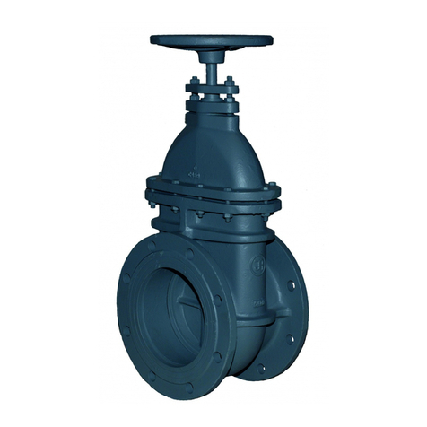
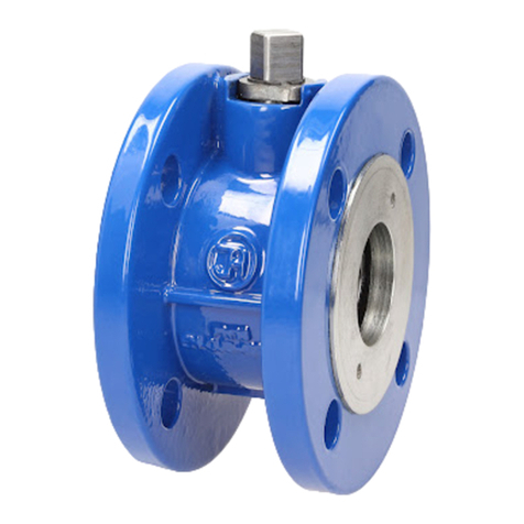
Flanged gate valves
with soft seals
P/N 2111 2002 under actuator 2911 2902
with actuator

OPERATING MANUAL 06-2021 2/8
TABLE OF CONTENTS
1.
INTENDED USE.......................................................................................................................................... 3
2.
TECHNICAL DESCRIPTION................................................................................................................... 3
3.
PRODUCT IDENTIFICATION MARKING............................................................................................ 4
4.
STORAGE & TRANSPORT ...................................................................................................................... 5
5.
INSTALLATION ......................................................................................................................................... 6
6.
OPERATION AND MAINTENANCE....................................................................................................... 7
7.
SAFETY........................................................................................................................................................ 8
8.
WARRANTY................................................................................................................................................ 8

OPERATING MANUAL 06-2021 3/8
1. INTENDED USE
The flanged gate valves with soft seals are intended for potable water supply systems, sanitary sewage systems
and (if approved by the manufacturer) industrial media systems. Each valve can be installed in above-ground and
underground pipelines as an integral inline part of the piping.
The gate valves are two-position valves which can only be set fully open or fully closed, and not intended for
operation as control or damper valves.
2. TECHNICAL DESCRIPTION
Production and acceptance according to EN 1074-2 (Valves for water supply. Fitness for purpose requirements
and appropriate verification tests. Isolating valves) and EN 12266-1 (Industrial valves. Testing of metallic
valves).
100% of each valve is leak tested.
Application temperature range: -10°C to +70°C.
Nominal diameter range: DN40 to DN1200 [mm].
Hydraulic performance: maximum medium flow rate for liquids 4 [m/s] and 30 [m/s] for gases.
Valve switching driving torque:
DN [mm]
DN [mm]DN [mm]
DN [mm]
Number of
Number of Number of
Number of
turns
turnsturns
turns
M
max
[Nm]
40
11
25
50
13.5
65
14
50
80
17
100
21
60
125
26
96
150
26
200
34.5
108
250
42.5
200
300
51
DN
DN DN
DN [mm]
[mm][mm]
[mm]
Number of
Number of Number of
Number of
turns
turnsturns
turns
M
max
[Nm]
350
60 264
400
58
280
450
65
300
500
63
350
600
77
420
700
52
636
800
52
768
900
58
864
1000
65
960
1200
78
1920
Valve control mode: the standard version of the gate valve has the clockwise closing sense of rotation. The
closing sense of rotation can be opposite on special order.
Connection flanges are manufactured in accordance with EN 1092-2 (Flanges and their joints. Circular flanges
for pipes, valves, fittings and accessories, PN designated. Cast iron flanges):
with the sizes compliant with the nominal pressure values.
The installation (face to face) length and its tolerance are per EN 558 (Industrial valves. Face-to-face and
centre-to-face dimensions of metal valves for use in flanged pipe systems. PN and Class designated valves):
Series 14, P/N 2111 (DN32-DN1200), 2911 (DN40-DN1200)
Series 15, P/N 2002 (DN32-DN1200), 2902 (DN40-DN1200)
Nominal pressure ratings: 0.6 MPa, 1.0 MPa, 1.6 MPa, and 2.5 MPa
The gate valves with soft seals a smooth walled bore, a non-ring spindle, and an o-ring spindle seal installed
in a head-type valve cover. The spindle is guided by a bushing in the valve cover neck and a sealing plug. The
spindle seal is effected by the plug sealing assembly, which is a system of O-rings. The gate valve closure is
a cast iron wedge completely coated with rubber and featuring sliding inserts as motion bearings. The spindle
can be controlled with an electric drive unit . The gate valves nominally sized from DN350 to DN1200 feature
the spindle seal in a separate valve head located on the valve cover with longitudinal bearings that support the
spindle flange. The standard valves above DN700 and up to DN1200 are operated with an angular gearbox.

OPERATING MANUAL 06-2021 4/8
3. PRODUCT IDENTIFICATION MARKING
The gate valve marking meets the following standards: EN 19 (Industrial valves. Marking metal fittings), Marking
of metallic valves), EN 1074-1 (Valves for water supply. Fitness for purpose requirements and appropriate
verification tests. Part 1: General requirements). The gate valve bodies feature markings on the front and back
walls of the body chamber. The marking contains the following data:
manufacturer's trademark;
heat no;
nominal diameter;
nominal pressure;
body material type;

OPERATING MANUAL 06-2021 5/8
The location on the valve specified in the documentation features the nameplate which contains the following
data:
1. Manufacturer's company and country of origin
2. Manufacturer's company logo
3. Polish construction mark (for the full range of diameter values)
4. Alphanumerical reference designation for the bolt hole pattern drilling on the flange to be connected to
the piping (PN)
5. CE marking
6. Maximum permitted pressure (PS)
7. Barcode
8. Maximum / minimum permissible temperature (TS)
9. Production serial no. in the calendar year
10. Seal material
11. Year of manufacture of the product
12. Diameter, bore and nominal size (DN)
13. Reference standard the product is compliant with
14. Product name
The gate valves with GSK RAL certified corrosion protection feature the corresponding label:
1.
GSK logo
2.
Certificate title
3.
Certificate reference
number
The gate valves may feature additional markings, which depends on the market they are sold on, including. NF,
WRAS, DVGW and other.
4. STORAGE & TRANSPORT
The products are packed on EURO pallets (1200x800 mm) or in custom containers, as applicable. Store the valves
in clean indoor rooms without bacteriological or chemical contaminants and at a room temperature between -20°C
and 70°C. Protect the paint coat and rubber parts from prolonged exposure to UV radiation. The filters should be
protected against mechanical damage.

OPERATING MANUAL 06-2021 6/8
Protect the rubber parts from compression by keeping the gate valve wedge closure halfway open. Secure the
products against shifting during shipping and handling. Heavy gate valves (DN350 and larger) shall be handled
with dedicated eye bolts; the gate valves from DN65 to DN300 shall be handled on slings (see the example diagram
below) and secured from rotating.
5. INSTALLATION
The flanged gate valves with soft seals can be installed in underground pipelines (except for P/N 2511 and 2502,
the buried installation of which requires a suitable chamber / vault) or overground pipeline installations, both
horizontal and vertical, with any direction of flow of the medium. Do not install the gate valve with the spindle
downward. The listed products are suitable for joining with the flanged ends of pipelines with the size equal to
that of the valve flanges. Note that the completed installation must not expose the valve to bending or tensile stress
from loading with the unsupported pipeline sections, and the valves must be installed aligned with the piping.
Consider proper compensation of the pipeline dimensional changes from temperature and pressure in the
installation. The gate valve is ready for installation as assembled and adjusted by the manufacturer. Any
dismantling of the gate valve components may result in loss of seal.
Before attempting to install the valve, check the technical and commercial documents delivered with the product
to verify that your media and pipeline operating parameters comply with the manufacturer's declaration. Any
change in the operating conditions must be consulted with the manufacturer beforehand.
Before attempting to assemble the valve, remove the main bore plugs, check the inner surfaces of the valve and
thoroughly flush with water, if necessary. Install the gate valve on a base or a support adequate to the size and
weight of the valve, to prevent strain of the piping with the valve. Use suitable piping flanges, gaskets and bolts
for the valve flange ends. The valve and piping flange holes must be aligned. Tighten the connection flange bolts
crosswise to ensure a proper seal pressure. The gate valve location must prevent exposure to freezing of the
medium flowing through the gate valve. Equip the gate valve with a suitable control - an electric drive unit. When
installing a housing, it is necessary to equip the unit with a street box founded on a base slab. When using a spindle
extension, make sure that the weight of the extension is not transferred to the gate valve spindle. To prevent the
load transfer, use holding pieces, mounted to the chamber/vault walls. Spindle extensions over 3000 mm long shall
be attached via Cardan joints. Having completed the installation, perform a pressure test at a maximum test
pressure equal to 1.5 times the nominal pressure.
Caution! If the product has mechanical damage, do not install it in the pipeline.
Caution! When mounting the valve with the electric actuator in the horizontal position, it is absolutely
necessary to use a support or slings in order to relieve the valve, see example below.

OPERATING MANUAL 06-2021 7/8
6. OPERATION AND MAINTENANCE
The gate valve shall be operated in accordance with all relevant requirements for stop valves, i.e. kept either in the
fully open or fully closed position. Leaving the gate valve partially opened (or closed) may result in seal failure.
The gate valve can be controlled with an electric drive unit.
Valve control requires a specific driving torque (see table in Section 2) and a specific number of spindle turns. Do
not exceed the maximum driving torque.
To ensure full operational efficiency, carry out a technical inspection and maintenance at least once a year as
follows:
Operate the gate valve from the fully open position to the fully closed position, or vice versa, as the case may
be.
Follow the driving torque limits specified in the table in Section 2.
If the valve operation is difficult, i.e. the valve reaches the maximum driving torque before either of its limit
positions (e.g. due to scale on the spindle threads), repeat the full operation three times.
Check the tightness of all connections and seals with the gate valve closed.
If all the actions above have been completed with a good result, visually inspect the corrosion protection. If
the paint coat is damaged, rebuild it with the paint kits available from JAFAR.
Replacing the seal in the cover:
Fully open the valve (until you clearly sense that the wedge closure (6) resists further movement; this will seal the
spindle under the flange (5)).
This operation allows you to replace the o-rings in the plug (2) or the whole plug assembly on the pipeline.
Clean the gate valve cover from dirt, sediments and grime.
Disassemble the following in the succession shown below:
the circlip (1).
Release and remove
the sealing plug (2) (with the service wrench tool available from the manufacturer).
1
2
3
4
5
6

OPERATING MANUAL 06-2021 8/8
Clean and moisten the seat in the cover.
Install the new sealing plug assembly (2) or clean the existing one and install its new o-rings.
Leak test the valve in the OPEN POSITION to confirm that the sealing has been properly replaced.
Install the circlip in place to prevent secure the plug (1) in place.
The reassembled and positively tested valve will be ready for operation.
7. SAFETY
All installation and operation tasks related to the product shall be only be done by qualified professionals with
sufficient training and experience to assess the current situation and identify and avoid hazards. Failure to follow
this warning or this Operating Manual may cause death, severe bodily injury or substantial property damage.
Fabryka Armatur Jafar S.A. shall not be liable for any accidents or emergencies related to incorrect installation or
operation of the product. Note that the valve installation could be pressurized or contain various type of stray gas
or aggressive liquids. If the installation is operated explosion hazard zones, ATEX requirements may apply; this
will require suitably trained professionals (according to ATEX requirements). Do not use tools which may generate
electrostatic discharge in the ATEX zone.
Do not use the product without thorough knowledge and understanding of this Operating Manual. Follow the
general health and safety rules. Keep this Operating Manual throughout the service life of the product to ensure a
safe operation of the latter.
8. WARRANTY
The product assembled, installed and operated in compliance with this Operating Manual and the Product
Specification Sheet is covered by a commercial warranty from the manufacturer. The warranty terms, conditions
and period are specified in the Warranty Certificate available from www.jafar.com.pl.
The manufacturer may provide this product with custom materials and modifications on order. The final selection
of the product which meets the optimum criteria for the installation project in question is made by the installation
designer, who should consider this Operating Manual along with other data and information of significance for the
correct operation of the product.
Failure to comply with the guidelines and instructions in this Operation and Maintenance Manual releases the
manufacturer from all obligations, liability and warranty. Due to continuous business development, the
manufacturer reserves the right to modify and change the design of the product shown herein.
Other manuals for 2911
1
This manual suits for next models
3
Table of contents
Other Jafar Control Unit manuals
Popular Control Unit manuals by other brands

SEW-Eurodrive
SEW-Eurodrive Movidrive MDX61B manual

Armstrong
Armstrong BRAIN DMC80 manual

Keysight
Keysight M9164A Startup and Service Guide

MG
MG Devicenet R7F4DD-DA16A-H instruction manual

Honeywell
Honeywell SILENT KNIGHT IDP-Control-6 Installation and maintenance instructions

Grand Canyon Gas Logs
Grand Canyon Gas Logs 3BRN-18 Installation and operation guide