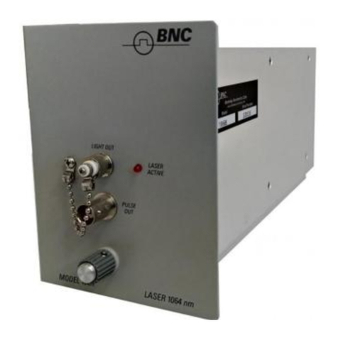
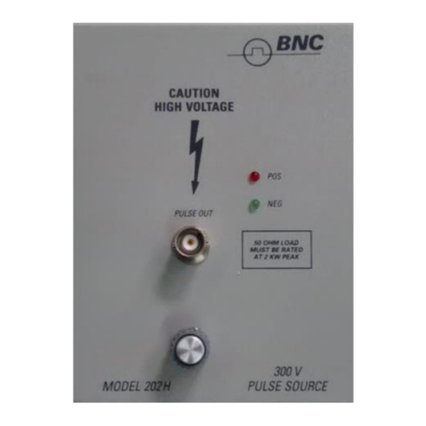
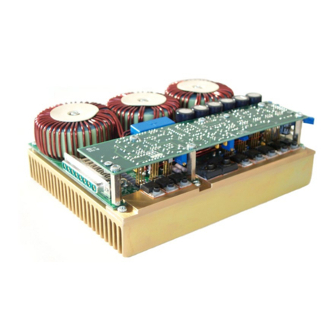
BNC 106C User manual

Instruction Manual
Model 106C/130/155
Optical Module
Berkeley Nucleonics Corporation
2955 Kerner Blvd. San Rafael, CA 94901
Ph: 415-453-9955 Fx: 415-453-9956
www.berkeleynucleonics.com

2
WARRANTY
Berkeley Nucleonics Corporation warrants all instruments, including
component parts, to be free from defects in material and workmanship,
under normal use and service for a period of one year. If repairs are
required during the warranty period, contact the factory for component
replacement or shipping instructions. Include serial number of the
instrument. This warranty is void if the unit is repaired or altered by others
than those authorized by Berkeley Nucleonics Corporation.

3
CONTENTS
Page
SECTION 1 SPECIFICATIONS 7
Model 106C, 155 and 130 Characteristics 7
Module Status Byte Summary 9
SECTION 2 OPERATING INFORMATION 10
Features 10
General 11
Power Up 11
Module Installation 11
Safety Precautions 11
Warm Up Requirements 11
Troubleshooting 11
Default Settings 12
Front Panel Description 12
LED Indicators 12
Connectors 13
Rear Panel Description 13
Mainframe Operation 13
Front Panel Programming 13
Remote Programming 16
SECTION 3 THEORY OF OPERATION 17
General 17
Module Interface 17
Laser Driver Output 17
Circuit Description 18
Module Interface Board 18
Laser Output Board 20
Inputs and Control Signals 20
Laser Module 21
CW Mode 21
External Modulation Mode 23
Pulse Mode 24
Pulse Mode (Nonzero Baseline) 24
Pulse Mode (Zero Baseline) 25
External Drive 25
Impulse Mode 25
Laser Protection 26

4
CONTENTS
SECTION 4 MAINTENANCE AND CALIBRATION 27
Maintenance 27
Light Output Connector 27
Calibration 27
General 27
Equipment Required 27
Procedure 28
Module Interface DAC Calibration 28
External Drive Discriminator 28
CW and External Modulation Calibration 29
Pulse Baseline Calibration 29
Pulse Peak Calibration 29
Pulse Dynamic Characteristics 30
SECTION 5 PARTS LISTS AND SCHEMATICS 31
Parts List 31
Laser Output Board, 155-1 31
Module Interface Board, 6040-4 35
Schematics Dwg.No.
Interconnection Diagram 155-30
Module Interface Board 6040-35A
Laser Output Board 155-31

5
CONTENTS
ILLUSTRATIONS
Figure No. Page
1-1 Trigger and Output Pulse Timing
2-1 Safety Labels
3-1 Module Interface Block Diagram
3-2 Laser Output Block Diagram
TABLES
Table No. Page
1-1 Module Status Byte Summary 9
2-1 Menu Keys for the 135/130 Module 14
3-1 Plug-In Module Memory Map 19
3-2 Control Signals 22

6
1064nm, 1560nm AND 1310nm OPTICAL MODULES
MODEL 106C, MODEL 155 AND MODEL 130
Graphic (Model 155 & 130)
The Model 106C, Model 155 and Model 130 are three in a series of plug-in modules that provide
electrical and optical output pulses when installed in the Model 6040 mainframe.
These particular modules provide optical pulses of 1064, 1560 and 1310 nm wavelengths at peak levels
to 1 mV at rates to 100 MHz.

7
SECTION 1
SPECIFICATIONS
MODEL 106C/155/130 CHARACTERISTICS
Timing Characteristics
Rep Rate: 0 Hz-100 MHz
Width: 3 ns - 640 s (Pulse Mode); 3 ns (min.) at reduced
amplitude.
Impulses, fixed 400 ps fwhm (typical).
Input Characteristics
EXTERNAL DRIVE
Range: dc - 300 MHz (200 MHz for zero Baseline level):
specifications apply dc - 100 MHz.
Input Impedance: 50 ohms.
Minimum Signal Amplitude: 300 mV.
Maximum Signal Amplitude: ±7 V dc or 10 V ac p-p.
Minimum Width: 5 ns; 3 ns (min.) at reduced amplitude.
Threshold Range: ±2.5 V.
Threshold Resolution: 10 mV.
Insertion Delay: 5 ns, typical (between EXT DR and LIGHT OUT).
Jitter: 30 ps rms (between EXT DR and LIGHT OUT).
Connector: Threaded SMA (3 mm).
EXTERNAL MODE
Range: 100 Hz to 700 MHz (-3 dB).
Input Impedance: 50 ohms.
Sensitivity: 200 mV rms/mW, typical.
Maximum Signal Amplitude: ±2 V dc or 3 V ac p-p.
Total Harmonic Distortion: < 20 dB below fundamental (0.5 mW avg, level with
0.5 mW rms modulation).
Insertion Delay: 5 ns, typical (between EXT MOD and LIGHT OUT).
Connector: Threaded SMA (3 mm).

8
SPECIFICATIONS cont’d.
Output Characteristics
LIGHT OUT
Wavelength: Model 106C: 1064nm ±30 nm
Model 155:1550 nm ±30 nm.
Model 130:1310 nm ±50 nm.
Spectral Width: 2 nm rms (from 50 uW to 1 mW).
Power Level: 1 mW max. (Peak or Baseline). 0 mW min.
Impulse is fixed at 50 µW Baseline and 0.5 mW Peak
(typical).
Power Level Resolution: 5 µW (from 50 µW to 1 mW),
Extinction Ratio: CW Mode and External Modulation Mode, has 5 µW
resolution from 0 to 1 mW
Mesial Level: ∞(zero Baseline), or 20.0 to 1.01.
Pulse Adjustment Range: 25 µW (zero Baseline), or 55 µW to 0.995 mW.
(Max. pulse size: min. pulse size.) 20 dB (non-zero
Baseline), 13 dB (zero Baseline), 20 dB (CW.
External
Modulation).
Accuracy, Absolute: ±1 dB (from 50 µW to 1 mW).
Accuracy, Relative: ±0.5 dB (±10 %) from 100 µW to 1 mW (Pulse
Mode).
±0.05 dB (±0.5 %) from 50 µW to 1 mW (CW.
External
Modulation).
Temperature Coefficient: 0.05 dB/°C.
Transition Times (10 to 90%): 0.5 ns rise time, 1 ns fall time (zero Baseline),
1 ns rise time, 1 ns fall time (nonzero Baseline).
Insertion Delay: 35 ns, typical (between mainframe TRIG OUT and
LIGHT OUT; see Figure 1-1).
Jitter: 100 ps rms (between mainframe TRIG OUT and
LIGHTOUT).
Connector: ST, 8/125 um single-mode fiber, 0.12 NA (contact
factory for other connectors).

9
SPECIFICATIONS cont’d.
Modes
PULSE Conventional pulse generator with rate, delay, width
and single/double pulse selections controlled by
the 6040 mainframe. External Drive operation
produces pulses corresponding in rate and duty
cycle to an external pulse train.
EXTERNAL MODULATION Converts digital and analog electrical signals are into
their optical equivalent.
IMPULSE Provides a narrow pulse of fixed width and
amplitude, with rate and delay controlled by the 6040
mainframe.
Module Status Byte Summary
Table 1-1. Module Status Byte
Bit Description
7 Always zero
6 Always zero
3 Always zero
4 Always zero
3 Always zero
2 Always zero
1 Laser Active
0 Laser Guard

10
SECTION 2
OPERATING INFORMATION
FEATURES
The Model 106C, 155 and 130 plug-in modules provide 1064nm, 1550 nm and 1310 nm optical output
sources for the Model 6040 Universal Pulse Generator. Accurate and adjustable outputs are available for
all of the four modes in which the 6040 mainframe can operate.
In Pulse Mode operation, the 106C/155/130 supplies flat-topped pulses with fast rise and fall times and
independently adjustable Peak and Baseline levels. The timing for these pulses may be supplied in a
number of ways.
A delayed pulse of adjustable width may be generated by the mainframe. This delay can be specified
with respect to an internal trigger occurring at a selected repetition rate or with respect to an externally
supplied trigger signal (TRIG IN). In addition, Single Cycle operation allows the user to trigger the
instrument manually, using a pushbutton (or using remote programming). In each case a trigger out
signal (TRIG OUT) is provided by the 6040 for reference (see Figure 1-1). Double Pulse operation,
producing both an initial and delayed pulse put of the same jack may be selected for any trigger choice.
For all of these timing options, the mainframe supplies electrical output pulses (PULSE OUT) coincident
with the module's optical output (LIGHT OUT).
External Drive operation is also available in the Pulse Mode. This allows a drive signal, supplied by the
user to the module's front panel (EXT DR), to generate the optical pulses directly. The occurrence and
duration of each light pulse will correspond to that of each pulse in the external drive signal: when the
EXT DR pulse goes high, the light pulse goes to the Peak value. Peak and Baseline output levels remain
specified by the mainframe (as well as the threshold level for the external drive signal). With External
Drive, the mainframe's pulse and trigger outputs are disabled.
In External Modulation Mode, an electrical signal supplied to the module's front panel (EXT MOD) by the
user will be converted into its optical analog. The quiescent optical level, corresponding to the zero point
that the input signal modulates about, is selected by the mainframe (External Modulation Level), but no
other parameters can be altered.
In the Impulse Mode, a narrow optical pulse of fixed width and amplitude is produced at the module
output (LIGHT OUT) with a corresponding pulse (of 5 ns duration) appearing at the mainframe (PULSE
OUT). As with the Pulse Mode, the trigger source may be internal, external or from manual (or remote
programming) control. Either a single delayed impulse or a pair of impulses separated by a delay may be
obtained. In Impulse Mode, External Drive operation is disabled; and Peak and Baseline Level settings
also have no effect.
CW Mode results in a steady-state optical output. The output power level in this Mode may
be adjusted by the mainframe (CW Level).
For more detailed information on the characteristics of each Mode and hour to control the module from
the mainframe, see the Specifications section and the 6040 manual.

11
OPERATING INFORMATION
General
POWER UP
When power is applied to the 6040 mainframe with a 106C, 155 or 130 module installed, the instrument
settings from the module's memory 0 are activated. The mainframe automatically checks what type of
plug-in module is in place and loads the appropriate parameters. The LCD, after showing the
mainframe's software version number and performing a memory check, will display "106C Ver. x.x" (or
“155 Ver. X.x” or "130 Ver. x.x") where "x.x" is the version number of the module.
Module Installation
The module must be installed with mainframe power off. A module can be damaged or have its
memory corrupted if inserted or removed from the mainframe with the power on. To install the module,
simply slide it in and tighten the mount screw knob.
Safety Precautions
Laser light emitted from the end of the connected light fiber is invisible. Fibers should be terminated in a
system which will not allow human exposure to this radiation. Do not stare into the beam or into a beam
from a reflecting surface. Use of controls or adjustments or performance procedures other than those
specified herein may result in hazardous exposure. Safety labels attached to the module are shown in
Figure 2-1.
Always keep the LIGHT OUT connector covered with the dust cap when a fiber is not attached in order to
avoid hazardous exposure and to keep the connector as clean as possible.
Warm Up Requirements
No warm up period, other than that necessary for the mainframe itself, is required.
TROUBLESHOOTING
Follow the procedure in the Troubleshooting section of the 6040 manual. Make sure that the module is
seated correctly in the mainframe. If the module's memory has been corrupted, a cold boot will put the
module's default settings (given below) into effect (as described in the Cold Boot paragraph in the 6040
manual).

12
OPERATING INFORMATION cont’d
The Quick Test procedure for the mainframe may be applied to the 106C/155/130 by selecting the Pulse
Mode and following the test sequence using the module's LIGHT OUT connector and an optical detector
in place of the mainframe's PULSE OUT. After Pulse Mode operation has been verified, the Impulse
Mode can be tested. This will require a sampling oscilloscope with a 1 GHz bandwidth. The impulse
should appear as a narrow pulse (approximately 400 ps). Its amplitude is roughly equal to that of a 0.3
mW, 5 ns pulse generated in the Pulse Mode. The CW and External Modulation Modes are similar.
These should produce continuous outputs. The output under External Modulation should follow any
waveform presented to the module's EXT MOD connector.
Default Settings
The following default settings for the 106C/153/130 module go into effect whenever a cold boot is
performed.
MODE: Pulse
TRIG: Single Cycle
(with other values set as follows)
Internal Trigger Rate = 1 kHz.
External Trigger Threshold = 0.00 V
Trigger Slope +
External Drive Threshold = 0.00 V
TIMING: Delay = 1 µs
Width = 1 µs
Single Pulse
LEVEL: Peak= l.000 mW
Baseline = 0.000 mW
External Modulation
CW=0.00 mW
GPIB/RS232: GPIB Address = 6
Baud Rate = 1200
Full Duplex
Remote Enabled
Front Panel Descriptions
LED INDICATORS
The 106C/155/130 module has two LED indicators on the front panel.
LASER ACTIVE will light when the instrument is in a state that can produce a light output.
LASER GUARD will light if the laser is being protected from an unsafe power output level, whenever the
Mode is changed and when the unit is first turned on. LASER GUARD will remain on if any unsafe circuit
conditions exist (e.g., excessive current driving the laser).

13
OPERATING INFORMATION cont’d
CONNECTORS
Three connectors appear on the 106C/155/130 module front panel.
LIGHT OUT provides the optical output from the module. A single-mode 8/123 Mm fiber with an ST
connector is required (the unit can be configured for other connectors; consult the factory for details). To
keep dust out of the connector when a fiber is not attached, a dust cap is provided.
EXT DR (External Drive) is a threaded SMA (3 mm) connector for accepting drive signal inputs to the
module.
EXT MOD (External Modulation) is a threaded SMA (3 mm) connector that accepts external signals to
modulate the instantaneous light output power level.
Rear Panel Description
The rear panel of the 106C/155/130 module has a mounting screw (for installation into the mainframe),
one 40-pin edge connector, and one SMA connector.
The 40-pin connector allows the 6040 mainframe to control and communicate with the module and also
supplies the power to the module.
The SMA (snap-on type) connector receives the high speed pulse generator DRIVE signal from the
mainframe. This signal is an ECL version of the mainframe's front panel PULSE OUT.
Mainframe Operation
This section presents information on how to operate the Model 6040 Universal Pulse Generator with the
Model 106C, 155 or Model 130 optical module installed. Only the details that are specific to the module
are described. For an overall description of how to use the mainframe with plug-in modules, please refer
to the 6040 manual.
Front Panel Programming
When operating the instrument from the front panel, certain control keys have module dependent action,
as indicated in the 6040 manual. The aspects of these keys, and the menus they control, that are not
general to the mainframe will be listed here.
An overall chart of the menu keys, showing which menu selections have control in each Mode, is given in
Table 2-1. An “x” in the column for a given Mode indicates that the menu selection operates in that Mode.

14
OPERATING INFORMATION cont’d
Table 2-1. Menu Keys for the 133/130 Module.
MODE Menu
Pulse
Impulse
CW
External
Modulation
TRIG Menu
X
X
X
X
Single Cycle
Internal Trigger (and Rate)
External Trigger (and Threshold)
External Trigger Slope
External Drive (and Threshold)
TIMING Menu
X X
X
Delay
Width
Single/Double Pulse X X
LEVEL Menu
X
X
X
Peak
Baseline
CW
External Modulation X

15
OPERATING INFORMATION cont’d
{MODE} The Mode menu for the 106C/155/130 has all four selections available: Pulse,
Impulse,
CW and External Modulation.
Pulse Mode can operate over the entire timing range of the 6040, producing flat-
topped delayed pulses. The Delay interval, Peak level. Baseline level and pulse
Width are all adjustable.
External Drive operation is available in this Mode, allowing the module to be
digitally modulated at rates from zero to 300 MHz (for nonzero Baseline levels) or
200 MHz (for zero Baseline level).
Impulse Mode produces pulses of fixed 400 ps width with fixed 30 u¥ baseline and
1 mW peak levels (typical).
CW Mode provides continuous wave optical output.
External Modulation Mode allows a user-provided analog or digital signal to be
linearly converted to its optical equivalent. Inputs ranging from 100 Hz to 700 MHz
are converted with 200 mV rms/mW sensitivity (typical).
{TRIG} The Trigger source and parameter menu, which operates in the Pulse and Impulse
Modes, has all five menu items: Single/Double Cycle, Internal Trigger (and Rate),
External Trigger (and Threshold), External Trigger Slope, and External Drive (and
Threshold).
Internal Trigger Rate and External Trigger Threshold are adjustable over the
6040's entire range.
External Drive is valid only in Pulse Mode (and has no effect in Impulse Mode).
The External Drive Threshold for the discriminator on the EXT DR input to the
module is adjustable from -2.3 V to +2.3 V with 10 mV resolution.
{TIMING} This module places no constraints on timing settings selected with the Timing
parameter menu.

16
OPERATING INFORMATION cont’d
{LEVEL} All four Level parameter menu selections are available for this module: Peak
Level, Baseline Level, External Modulation Level and CW Level.
Peak and Baseline Levels select the high and low power levels in Pulse Mode
operation. These levels may be set to zero or they may be adjusted between 30
µW and 1 mW in 3 MW steps (levels between zero and 50 µW may be selected
but output characteristics are not guaranteed). Peak Level and Baseline Level may
be set independently, but if Peak is set below Baseline the output will be a
constant CW at the Baseline Level.
External Modulation Level sets the quiescent optical power level. This may be
selected over the entire range of zero to 1 mW in 3 MW steps.
CW Level may also be adjusted to any power level between zero and 1 mW with 5
µW resolution.
{UNITS} This key is not used with the 106C/155/130 module (and has no effect).
FUNCTION KEYS These keys are not used with the 106C/155/130 module (and have no effect).
{A}, {B}, {C}
Remote Programming
The remote programming commands that are specific to this module correspond to the module
dependent front panel commands, as described in the previous section. Consult the 6040 manual and
the above section for details on controlling the instrument with remote programming. The Module Status
command, the only command that is specific to the 155/130 module, will be described here.
PS Module Status: This command returns the Module Status byte for the 155/130.
Module Status Byte:
Bit Description
7 Always zero
6 Always zero
5 Always zero
4 Always zero
3 Always zero
2 Always zero
1 Laser Active
0 Laser Guard
Bits 2-7: These bits are always zero and are reserved for future use.
Bit 1: This bit is set if the LASER ACTIVE LED is lit.
Bit 0: This bit is set if the LASER GUARD LED is lit.

17
SECTION 3
THEORY OF OPERATION
GENERAL
Module Interface
Figure 3-1 shows a simplified block diagram of the Module Interface board. The path for communication
between mainframe and module is via PS. The eight QAD lines and five QA lines are the bus interface
lines, and a MOD DIS line is used for disabling the Output board. Power is also delivered by P8.
The address demultiplexer and select logic circuitry decodes the bus signals and selects one of the other
blocks.
The I.D. ROM contains information necessary for operation specific to the Output board. This includes
boundaries for parameters, values used to initialize the nonvolatile RAM (NVRAM), and the version
number of the I.D. ROM.
The nonvolatile RAM is used for saving and retrieving ten panel settings. It also holds the GPIB/RS232
bus settings.
The digital control circuits are used to monitor and set the operating state of the Output board. The DACs
and amplifiers allow setting of up to four analog values used for level control. All of the control, status,
and analog signals are delivered to the Output board by two 20-pin connectors, J1 and J2.
Laser Driver Output
Figure 3-2 shows a simplified block diagram of the Laser Output board. The connection to the Module
Interface board is shown in the lower left hand corner. There are three analog lines used to set the output
levels and the threshold of the External Drive discriminator. The control lines select which Mode the
Laser Output will operate in.
The selection of the digital drive source is controlled by three digital control lines, EXT DRIVE ENABLE,
IMPULSE, and EXT MOD. These determine which of the two drive sources will be controlling the state of
S1, (a high speed transistor switch). A discriminator, whose threshold is set by the analog voltage EXT
DRIVE LEVEL, is connected to the drive source from the front panel EXT DR connector. The other signal
source is the rear panel DRIVE connector which delivers the mainframe's pulse generator output.
The level control circuitry sets one or both of the current sources as determined by the analog inputs
PEAK LEVEL, and BASELINE LEVEL and the Mode control lines. During the Impulse, CY and External
Modulation Modes, it uses the PIN detector in the laser module to monitor and stabilize the laser's
output. When LASER GUARD is active, the current sources are set for zero output.

18
THEORY OF OPERATION
The two current sources are used for different Modes. The current source on the left is used during Pulse
and Impulse Modes (to supply the Peak level), and during the External Modulation Mode. This current
source can be modulated from a wideband preamp which is driven by the front panel SMA connector
EXT MOD. The current is switched to the laser by SI, as determined by the DIGITAL DRIVE SELECT
and the drive signals. The current source on the right is used during PULSE MODE when a nonzero
Baseline level is selected and in the CW Mode.
The Laser Protection circuitry monitors the laser output and circuit conditions. If the laser output exceeds
a preset level, S2 will be closed and all laser drive current will be shunted to ground. The current is then
monitored until it is reduced below another preset value before S2 is allowed to reopen. This block drives
the front panel LEDs, LASER ACTIVE and LASER GUARD, which allow the user to monitor the state of
these circuits. The DAC EN signal is used to notify the Module Interface board of a potential problem and
disable its DACs, thus setting all level control voltages to zero. The MOD DIS signal is used to disable
the module's output.
The Laser Module is a single package that contains the laser diode, a PIN monitor diode, a
thermoelectric cooler (TEC), and a temperature sensing device. An 8/123 Um single-mode fiber is
connected to the front panel (LIGHT OUT). The TEC and thermistor are used in conjunction with an op
amp and transistor to regulate the temperature of the laser diode, thus improving power and wavelength
stability.
CIRCUIT DESCRIPTION
Module Interface Board (Schematic 6040-35)
The Module Interface board contains all the necessary circuits to allow the 6040 mainframe to control the
module. Interfacing between the module and the mainframe is realized via the 40-pin edge connector,
PS, This delivers eight data bits (QADO-QAD7) and 13 address bits (QADO-QAD7, multiplexed, and
QA8-QA12, nonmultiplexed). P8 also delivers power to the Interface board and the Output board.
Z2 is an eight bit latch that demultiplexes QADO-QAD7 to produce the lower eight address bits QAO-
QA7. This allows up to 8K bytes to be addressed within the Interface board, though not all of this is
utilized at the present time. Table 3-1 gives the memory map for the module.
Z1 is a dual quad selector. Z1 A is used to select between one of four 2K byte segments. These four
segments are used for: 1) Z3, the I.D. ROM; 2) Z4, the nonvolatile RAM; 3) reserved for expansion; 4)
Z5, Z6 and Z7, the digital and analog control of the output board. Z1B selects which IC in the fourth
segment is accessed.
Z3 is the I.D. ROM. It is an 8K byte ROM (only the lower 2K is used) that contains the module dependent
information necessary for the 60-40 to operate correctly.

19
THEORY OF OPERATION
Table 3-1. Plug-In Module Memory Map
Memory Range
C000-C777 Z3, I.D.ROM
C800-CFFF Unused
D000-D7FF Z4, Nonvolatile RAM (NVRAM)
D800-DFFF I/O
D800-DFFF
D800-D9FF Z5, 82C55 PPI
D800 Port A
D801 Port B
D802 Port C
D803 Control
DA00-DBFF Unused
DC00-DDFF Z6, 7528; Dual DAC
DC00-DC03 PEAK LEVEL
DC04-DC07 BASELINE LEVEL
DE00-DFFF B27, 7528; Dual DAC
DEOO-DE03 SPARE
DE04-DE07 EXT DRIVE LEVEL

20
THEORY OF OPERATION
This includes the Modes that are valid, parameter boundaries, and the type of output that the module has
(optical or electrical). It also contains the values for initializing the nonvolatile RAM.
Z4 is a 2K byte nonvolatile RAM (NVRAM). It is used to save instrument settings and power-on
conditions.
Z5 is a configurable Parallel Peripheral Interface 1C set up to allow 16 bits of output and eight bits of
input. The outputs are used to select the operating state of the Output board while the inputs monitor the
board's status.
DACs Z6 and Z7. in conjunction with op amps Z8 and Z9, generate analog signals that set the value of
the Peak, Baseline, and quiescent level of the output. They are also used to set the threshold level for
the External Drive discriminator. The variable resistors, R3-R6, are used to compensate for slight
differences in the DACs.
The voltage reference for the analog signals is CR1, a 6.2 V temperature compensated zener diode. Q1
is used to disable CR1 if the signal DAC EN is allowed to go up to +12 V. The Output board asserts this
in the event of a Mode change or if any unusual condition is detected.
The MOD DISABLE line allows the Output board to be disabled via the 6040 rear panel MODULE
DISABLE connector.
The Module Interface board has two grounds, digital and analog. The analog ground is used exclusively
by the DAC and op amp circuitry (Z6, Z7, Z8, Z9, etc.), while all other circuitry is connected to digital
ground. These are separated to prevent any noise or dc offsets by power supply return currents from
affecting the analog control voltages.
The 20-pin connectors J1 and J2 deliver the digital and analog control signals to the Output board, while
the 16-pin connector J11 delivers the power supply voltages. J3 is an expansion connector to be used in
conjunction with future modules.
LASER OUTPUT BOARD (Schematic 155-31)
Inputs and Control Signals (Schematic Sheets 1 and 2)
The Laser Output board receives three types of inputs: digital control signals from the Interface board via
P1, analog control signals from the Interface board via P2, and drive and external modulation inputs via
front or rear panel coax connectors. Four of the digital control signals, IMPULSE, EXT MOD, CW, and
BIAS, are used to control analog switches, Z14 and Z11 (sheet 1). These switches are in their low
impedance (closed) state when the control input, the terminal with inversion circle, is low (near ground).
This manual suits for next models
2
Table of contents
Other BNC Control Unit manuals
Popular Control Unit manuals by other brands

DH Instruments
DH Instruments PG7600 installation instructions

Watts
Watts 957 Series installation instructions

DeZurik
DeZurik APCO CVS-6000 Installation, operation and maintenance manual

AT&T
AT&T 7506 user manual

Highcross
Highcross ECM-RS2D Quick reference guide

Bosch
Bosch KTS 5 Series Original instructions