SIAM SIDDOS-automat 3M User manual

Limited Liability Company
Tomsk Scientific Introduction Innovation Company “SIAM”
DYNAMOGRAPH
«SIDDOS-automat 3М»
OPERATION MANUAL
Russia
2019

2

3
CONTENTS
1. OVERVIEW........................................................................................................... 4
2. BASIC SPECIFICATIONS .................................................................................. 5
3. COMPONENTS AND DELIVERY SET............................................................. 6
3.1. BASIC SET .............................................................................................................. 6
3.2 LOAD CELL KIT ....................................................................................................... 6
4.1 GENERAL PROVISIONS (REGULATORY FRAMEWORK).............................................. 7
4.1.1 Requirements to Personnel.............................................................................. 7
4.1.2 Requirements to the test object ....................................................................... 8
4.2 SAFETY MEASURES DURING THE OPERATION ........................................................ 10
4.2.1 Basic requirements........................................................................................ 10
4.2.2 Preparation of surface facilities..................................................................... 12
4.3 SAFE ASSEMBLY FOR THE DYNAMOGRAPH............................................................ 12
4.4 THE PROCEDURE OF SAFE DISASSEMBLY OF THE DYNAMOGRAPH ......................... 13
4.5. SCHEDULED MAINTENANCE AND REPAIR WORK................................................... 14
4.6. STORAGE AND TRANSPORTATION......................................................................... 15
5. ENSURING EXPLOSION-PROOFNESS OF THE PRODUCT. ................... 16
5.1. EXPLOSION-PROOFNESS OF THE PRODUCT............................................................ 16
5.2. MEASURES TO ENSURE AND KEEP THE DEVICE EXPLOSION-PROOFNESS DURING THE
ASSEMBLY,DISASSEMBLY AND REPAIR OF THE DYNAMOGRAPH................................. 17
6. GENERAL INFORMATION ON THE TOOL ................................................ 19
6.1 DESIGN AND USE OF DYNAMOGRAPH COMPONENTS.............................................. 19
6.2 DYNAMOGRAPH OPERATING PRINCIPLE ................................................................ 20
7. DYNAMOGRAPH OPERATION DESCRIPTION......................................... 20
7.1 SWITCHING ON AND SWITCHING OFF..................................................................... 21
7.2 WORK WITH THE GAUGES IN THE "SIAM SERVICE"APPLIED SOFTWARE.............. 21
7.3 BATTERY CHARGE................................................................................................. 24
8. DEVICE STORAGE AND TRANSPORTATION ........................................... 24
9. CLAIM INFORMATION................................................................................... 26

4
1. OVERVIEW
Dynamograph “SIDDOS-automat 3M” is a complex of electronic
devices and application software that provides automation of the
dynamogram control process, primary study processing and database
maintenance.
Testing process is conducted in an automatic mode. All the research
types require no more than one operator (two operators at use of the gauge
without the lifting mechanism). Graphs and numeric data of the studies are
visualized using an external terminal (smartphone/tablet/well pad data
collection modem).
The devices are explosion-proof designed (type of protection -
intrinsically safe circuit) in accordance with the requirements of GOST
31610.0-2014 (IEC 60079-0:2011), GOST 31610.11-2014 (IEC 60079-
11.), GOST 31610:2011), and have 1Ex ib IIB T3 Gb Хexplosion proof
mark. The devices are intended for indoor and outdoor installation in
potentially explosive gas atmosphere where atmospheric explosives of IIA,
IIB categories and T1, T2, T3 groups can form according to GOST R IEC
60079-20-1-2011 in the operating temperature range from -40 ºC to +50
ºC. The device design is comply with the assigned explosion proof mark,
with the requirements of GOST IEC 60079-14-2013 and other regulatory
documents governing the use of electrical equipment in hazardous areas.
The recommended interval between device calibration test is 1 year.
To check the device transmission characteristics for compliance with the
requirements of technical specification and to reduce the device to the
technical specification the device is recommended to be calibrated at the
dynamograph control stand after the calibration period has expired.

5
2. BASIC SPECIFICATIONS
Parameter name
Norm on specifications
Explosion proof mark according to GOST 31610.0-
2014 (IEC 60079-0:2011)
1Ex ib IIB T3 Gb X
IP degree of protection according to GOST 14254-
2015
up to IP54
Load monitoring range
0 10 000 kgf
Displacement monitoring range
0,5 9,999 mm
Available pump speed of the sucker rod pump
horsehead
1.5 15 SPM
Load monitoring resolution
10 kgf
Displacement monitoring resolution
50 mm
Time of continuous operation (1-2 measures per 24
hours), up to
720 h.
Weight, not exceed
3,2 kg
Service life
5 years

6
3. COMPONENTS AND DELIVERY SET
3.1. Basic set
Item
Quantity
Note
1. SIDDOS-automat 3M gauge
1
2. Load cell kit
1
See more variants
in 3.2.
3. AC adapter
1
4. Charge cable
1
5. Bag for the dynamograph
1
6. Load cell supporting plate
2
7. «DB SIAM» and/or SiamService software
1
8. Operating documentation:
8.1. SIDDOS-automat 3М. Certificate
1
8.2. SIDDOS-automat 3М. Operation manual
1
8.3. DB SIAM/SiamService software user’s guide
1
8.4. Sucker rod pumping unit diagnostic with the use
of dynamograph “SIDDOS”. Dynamometry manual
1
3.2 Load cell kit
3.2.1 Version of dynamograph with DN-10M gauge (dynamograph
with built-in jacks)
Item
Quantity
Note
1. Load cell DN-10M with expanded jacks
1
2. Ratchet handle wrench for the expanded jacks
1
3. Spare parts and accessories
3.1. Shim
1
3.2. Bottom jack housing
1
3.3. Left jack spring
1
3.4. Right jack spring
1

7
4. SAFE OPERATION GUIDELINES
4.1 General Provisions (regulatory framework)
The design of the wellhead equipment is to be approved by the
Russian Technical Surveillance Agency (RTSA).
Preparation of the well for tests should be conducted in accordance
with the requirements of the current Manual and internal guidelines
for maintaining and testing wells approved by the head of the
company.
Test equipment is to be operated according to the operating
instructions supplied with the equipment.
Measures to ensure safety are regulated by labor protection
instructions for respective types of work approved by the
Company’s Department of Labour Protection and the Safety
Regulations in Oil and Gas Industry approved by the RTSA.
4.1.1 Requirements to Personnel
Well tests are to be carried out by individuals above 18 who have
secondary education and who are medically cleared for work.
Qualification requirements to the personnel:
-not below category 5 for oil and gas production operators;
-not below category 4 for well test operators.
The personnel must attend professional training in accordance with
the requirements of local instructions on well operation,
organization and study conduction. The professional stuff must also
study Safety rules in the oil and gas industry (by Federal
Environmental, Industrial and Nuclear Supervision Service of
Russia, - Federal Rules and Regulations (FNP) №101); Operational
Code for Electrical Installations (PUE), Chap. 7.3 “Electric
installations in hazardous areas”; Regulations for Technical
Maintenance (PTE) and safety regulations PTB, Chap. 3.2.

8
"Electrical installations in hazardous areas”. The personnel is
required to pass the relevant examinations.
Personnel must participate in on-the-job training session on
research equipment operation. The training session is given by the
manufacturing company.
The personnel quantity to operate the dynamograph is about 1-2
people.
4.1.2 Requirements to the test object
- Researches are carried out on producing wells equipped with
bottomhole rod pumps of any type and any design with drive from a sucker
rod pumping unit of SKN series according to GOST 5866-56, SK
according to GOST 5866-76, SKD according to OST 26-16-08-87 of all
standard sizes, and similar foreign production.
- Column of rods of any length and configuration should end with
polished rod with diameter 19 - 36 mm.
- Packing of the polished rod should be made by sealing SUS1 or
SUS2.
- The connection between the rod and the sucker rod pumping unit
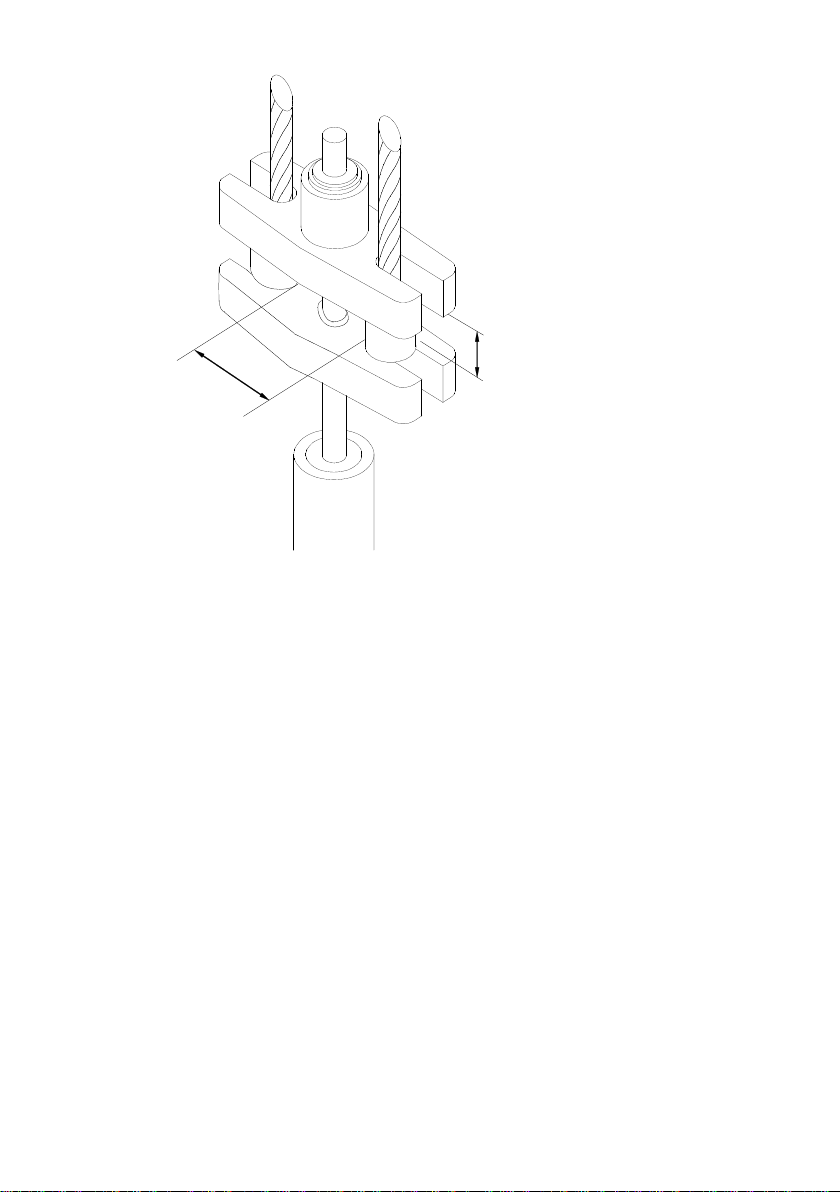
should be made by polished rod carrier bar of a PCSH-type wellhead rod.
When using a DN-10 load cell, the limits of the suspension configuration
are shown in Figure 1.
9
НЕ МЕНЕЕ 45 мм
НЕ МЕНЕЕ 105 мм
Figure 1. Carrier bar of wellhead polished rod
- Installation and operation of the sucker rod pumping unit and its
electrical equipment shall be carried out in accordance with the
"Regulations on Labor Safety in Oil and Gas Industry".
- The control station of the sucker rod pumping unit must have a
mode switch for manual operation.
- Moving parts of the sucker rod pumping unit (crank-connecting rod
mechanism, multiple V-belt drive) should have a proper standard fence.
- The SC gearbox must have a proper hand brake.
- The wellhead shall be equipped with a service platform for the
wellhead polished rod packing so that the upper end of the packing is not
more than 1 meter above the site, and the cable hanger cross-beams in the
extreme lower position of the horsehead are not more than 1.5 meters. The
distance between the lower hanger cross-beam and the cap of the head of
the wellhead should be at least 20 cm. (Figure 2).

10
Figure 2. Wellhead equipment
- The service site must meet the requirements of the "Oil and Gas
Industry Safety Regulations". The diagram of the site is shown in the
picture.
- If the height of the wellhead rod packing is low (up to 2 m above
the ground), portable sites may be used provided that they meet the above
requirements.
4.2 Safety measures during the operation
4.2.1 Basic requirements
When preparing, conducting research, assembling and
disassembling the equipment the personnel should be guided by the
“Safety rules in the oil and gas industry”, Operational Code for Electrical
Installations (PUE), Chap. 7.3 “Electric installations in hazardous areas”;
Regulations for Technical Maintenance (PTE) and safety regulations
(PTB), Chap. 3.2. "Electrical installations in hazardous areas”.
The following is prohibited:
-operation of a sucker rod pumping unit without a crank-

11
connecting rod mechanism and a V-belt drive;
- operating without stopping the sucker rod pumping unit;
- locating people under the sucker rod pump and its horsehead;
- turning the pulleys manually and braking them with non-standard
devices (pipes, scrap, etc.);
- using of non-standard means of switching the motor on and off;
-carrying out testing on a defective handbrake of a sucker rod
pumping unit;
- open fire using, smoke, use of non-explosive safety devices and
equipment.
Installation of the dynamograph should be performed only from the
sites intended for work with wellhead equipment.
Handle careful of all instruments of the complex. Carry and transport
the parts of the complex packed in standard cases. Avoid shock loads on
sensors.
Do not allow the presence of unauthorized persons at the site of the
investigated well during installation of the dynamograph and
measurements. It is prohibited to use non-standard installation tools and
technologies.
Before mounting the dynamograph, make sure that there are no
mechanical damages and make a total dynamograph function check.
If the space between cross-beams or the gauge is soiled, remove the
dirt with a rag.
The attachment of the cable to the wellhead assembly must ensure
that it does not collapse during start-up and operation of the sucker rod
pumping unit. When dismounting, the cable is removed from the mount
and, when stretched, is fed smoothly into the dynamograph reeling.
Start and stop of the sucker rod pumping unit is performed
according to the operating instructions of the sucker rod pumping unit.
During assembly, disassembly and operation, do not stand in front of
the dynamometer or place vehicles or other equipment in the danger area.
Operators and equipment must be located sideways on the windward side

12
of the well.
4.2.2 Preparation of surface facilities
Check the availability and serviceability of the handbrake, horsehead
holder, protective fences and service platform.
If the sucker rod pumping unit is operated in remote control mode or
in automatic mode, switch the control to manual according to the
instructions.
Hang up a sign on the starter: “Do not switch on, the operation is
under way”.
Make sure that the wellhead packing has no fluid passes at any rod
position.
4.3 Safe assembly for the dynamograph
Stop and brake the sucker rod pumping unit at the lower position of
the rod.
Align the gauge jacks so that they can fit freely between the cross-
beams.
Place the gauge in the cross-beam space with the jack screws
towards the balancer. Fasten the gauge with a safety chain to the
cable hanger elements. The jack's lower supports should rest on the
lower cross-beam in the entire plane. If the beam has an uneven
surface, a steel gasket of appropriate thickness and configuration
must be used.
Align the gauge with the cross-beam and polished rod in two
directions:
-the pier axis of the jack must match the longitudinal axis of the
top beam;
-the polished rod should be positioned symmetrically with
respect to the jacks.
Using the jacks, with the handle wrench, lift the top beam over
the thrust sleeve, successively twisting one or the other jack

13
until the wedges are completely brought together. As a result,
the upper crosshead should rise above the hanger thrust sleeve
and transfer the entire load to the gauge prism. It must be
ensured that the upper beam only transfers the load to the gauge
prisms and does not come into contact with the jack housing. A
gap of at least 2 mm between the beam and the jack housing
should remain.
4.4 The procedure of safe disassembly of the dynamograph
Stop the sucker rod pumping unit in the lower position.
Switch off the device if it is on.
Release the dynamo by successively loosening the jacks.
Unscrew the safety chain, remove the dynamo from the cross-
beam space, clean the dirt and place the device in the
transport box.

14
4.5. Scheduled maintenance and repair work
In case of malfunctions, please contact the manufacturer of the
complex or specialized organizations that have a certificate for repair
work from the manufacturer. Disassembly of the dynamograph and
other products of the complex leads to the loss of warranty.
- It is forbidden to disassemble the dynamograph and other elements
of the complex and perform repair work on the well.
- It is prohibited to charge the dynamograph batteries with a non-
standard charger. Charge the batteries in accordance with the operating
instructions of the complex with careful following its requirements.
- The charger is powered by AC 220V, 50Hz industrial AC power, so
take general precautions: do not plug the charger into faulty electrical
outlets, do not use extension cords, and do not leave turned on
devices unattended.
- Do not heavily pollute the gauges, especially the jacks and
measurement pyramids built into them. Remove the dirt with a rag.
Gasoline may be used with subsequent lubrication of coupling
screws.
- Check the condition of the fastening screws of the dynamograph at
regular intervals. When loosening, tighten them and secure with
paint.
- Do not allow dirt or sand to enter the connectors of the
dynamogaph. If dirty, flush the connectors with ethyl alcohol or
alcohol-gasoline mixture (9 parts alcohol, 1 part gasoline) using a
brush. Alcohol consumption - 100g per month of operation. After
washing it is recommended to apply a small amount of CYATIM
GOST6267-80 grease to the connectors surface.
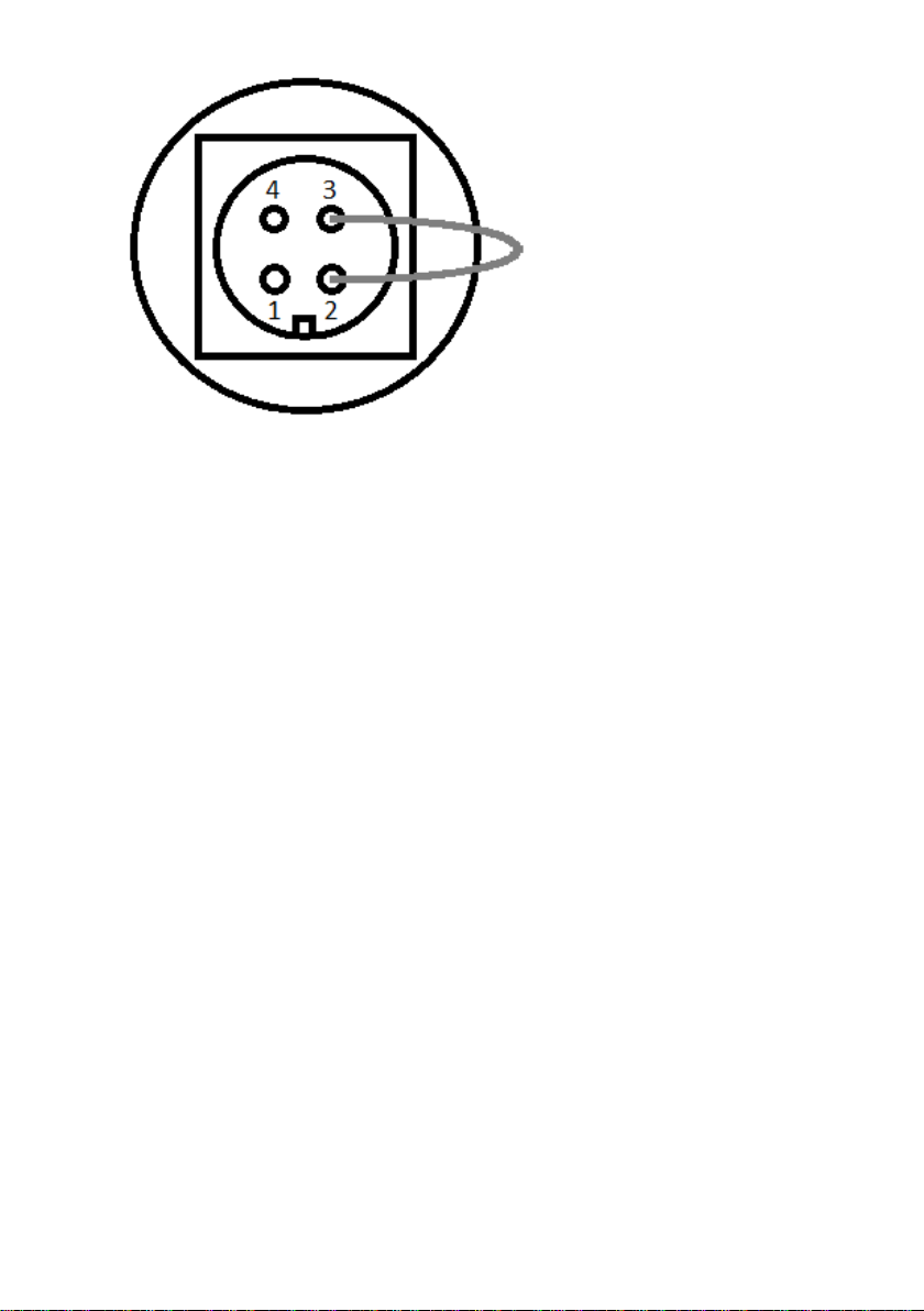
- At critical hang-up of the device and absence of any reaction from
it the device could be restarted forcibly by closing 2 and 3 contacts of
the connector with a metal object (a paper clip/piece of a wire) as
shown in the figure:
15
Front view of the connector. Short circuit 2 and 3 for the forced
restart.
4.6. Storage and transportation
Please store the tool in its standard bag in dry heated rooms with the
–10oC to + 40oC temperature range and moisture content of 80% and
below. While storing the tool, check the battery voltage every 2 months
(Section 6.13).
The tool can be transported using any type of transport at the –40oC
to + 50oC temperature range.

16
5. ENSURING EXPLOSION-PROOFNESS OF THE PRODUCT.
5.1. Explosion-proofness of the product
Explosion-proofness of the device is provided by the type of
protection "intrinsically safe electric circuit" “ib” level, according to the
requirements of GOST 31610.11-2014 (IEC 60079-11:2011), which is
achieved by the following:
Basic circuit diagram includes the protective component “Fib”. The
protective component “Fib” is an intact spark protection unit with the
short-circuit current limitation at 0.07 A (maximum), using current limiting
resistors and semiconductor fuses in series. Double redundancy is used in
the “Fib” protective component to ensure greater reliability. The “Fib”
component is integrated into the battery compartment of the device. The
design of the protective component “Fib” is met with the requirements of
GOST 31610.11-2014 (IEC 60079-11:2011), including leakages and
clearances. The minimum width of conductors on the PCB is 0.2 mm,
copper thickness is not less than 18 µm. Thus, the electrical circuit coming
out of the battery compartment of the device is intrinsically safe.
The electrical circuit principal and applied third party components
provide maximum power consumption not more than 1.5 W from the
internal battery with maximum possible voltage on it 7.2 V. The total
maximum capacity of the electrical circuit is 20 μF, maximum inductance
is not more than 200 µGn. The maximum current in the circuit during
normal operation is not more than 200 mA.
The battery has special made contacts which exclude the possibility
of its incorrect switching on (polarity reversal) and is located in the internal
battery compartment of the device. The design of the battery compartment
ensures that the battery does not fall out of the device. Do not replace the
battery and do not charge it in the hazardous area. For this reason, in order
to inform the user about special conditions of use of the device, the
identification plate of the device is marked with an "X" sign indicating
special conditions of safe operation.

17
The maximum temperature of overheating of components and
connections in the circuit diagram during normal operation is 15 °C max.
Thus, the surface temperature of conductors and elements during operation
and at maximum operating temperature plus 50 ° C is not more than 65 °
C. Device enclosures are made with the degree of protection against
external influences not lower than IP54 according to GOST 14254-2015.
5.2. Measures to ensure and keep the device explosion-proofness
during the assembly, disassembly and repair of the dynamograph.
5.2.1 Measures to ensure explosion-proofness before the production
process:
- The elements used in the protective component of “Fib”are
subjected to an acceptance test:
- resistors are tested for their nominal resistance;
- the fuses are checked against the short-circuit current limit;
- Materials used for casting the protective component “Fib”are
subjected to an acceptance test according to the certificates presented.
5.2.2 Measures to ensure explosion-proofness during production:
- The protective component “Fib”with the installed battery is
subjected to an outgoing inspection:
- the short-circuit current and open circuit voltage at the output of
the protective component are checked;
- visual inspection of the filling location is carried out in order to
confirm the absence of any foreign inclusions, bubbles, cracks or
stratification.
5.2.3 Measures to ensure explosion-proofness during operation:
- Check that the cover of the battery compartment and the
compartment itself (including the threaded connection) are free from
mechanical damage and corrosion. In case of corrosion or mechanical
damage, do not operate the device;

18
- meet the requirements specified by the "X" sign in the explosion
proof mark (see item 1.3.2 of TU 4273-004-20690774-2018).
5.2.4 Measures to ensure explosion-proofness during repair:
- the device must be repaired only by the employees of the
manufacturer.
Repair by third parties or individuals is prohibited.
- the protective component “Fib” is not to be repaired. It is made
intact and must be replaced in case of failure. Repair of the “Fib”
component is not permitted.
- after repair, the device must be tested according to the test
procedure, with the “Fib”component tested for short-circuit current and
open-circuit voltage (together with the battery installed).
19
6. GENERAL INFORMATION ON THE TOOL
6.1 Design and use of dynamograph components
Dynamograph "SIDDOS-automat 3" (hereinafter a dynamograph)
designed for integrated control of sucker rod pumping units (SGNU). It
provides automatic control of dynamograms such as "load - position of the
rod" in operating condition and when the well is start up, as well as valves
test in static condition. The special feature is the monoblock design of the
dynamograph. The design allows to exclude the connecting cable, which
increases the efficiency and safety of the test.
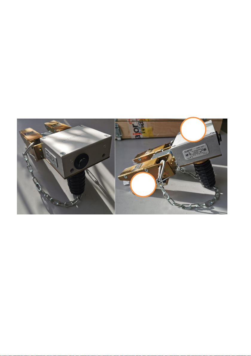
Figure 3 - Appearance of the gauge
The dinamograph consists of two modules: an electronic unit and a
load cell. The electronic block (1) is a microprocessor-based controller that
sets the algorithm of the complex, receives and processes data from the
displacement cell and load cell (2), and provides communication with
external devices wirelessly. The electronic block is connected to the cross-
beam load cell.
1
2

20
6.2 Dynamograph operating principle
The dynamograph operating principle is to simultaneously record the
change in time of load on the polished rod and its displacement at different
operating modes of the rocking machine.
In the dynamograph the type of test "DYNAMOGRAM" is
implemented - recording the dependence of load-position of the rod.
All the tests are conducted in automatic mode. The research
parameters are set by the operator. They can be changed at any time using
the external terminal software depending on the purpose of the test. The
last parameter setting is saved each time, thus simplifying the algorithm of
operating strictly on the well as much as possible.
All test results are memorized in the terminal software. They can be
viewed and transferred to a PC at any time.
Batteries are used as power cells to ensure long operating time. The
dynamograph monitors their status and is equipped with an integrated
charging controller.
7. DYNAMOGRAPH OPERATION DESCRIPTION
The dinamograph is equipped with two indicators. The indicator
"Сharging" shows the status of the device battery: battery is charged
(green), battery is empty (red), battery is charging (orange).
The "Power" indicator shows the status of the device: the device is in
operating mode (green), measurement is performed (flashing or burning
red), measurement error (flashing red after finishing deleting the
dynamograph).
A connector on the front panel is provided for charging the device
battery.
Table of contents
Other SIAM Industrial Equipment manuals

Popular Industrial Equipment manuals by other brands


Badger Meter
Badger Meter ER-10 user manual

Alfa Network
Alfa Network CR6 Original instruction

Signode
Signode GRIPPACK Original Operation, Parts & Safety Manual

Hillco
Hillco CS9030 Operator's manual

IEMCA
IEMCA BOSS 552 - IC Manual for use and maintenance

SCHUNK
SCHUNK TCU-P Series Assembly and operating manual