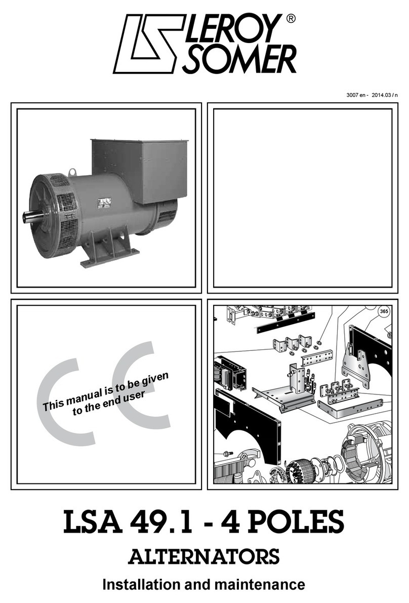
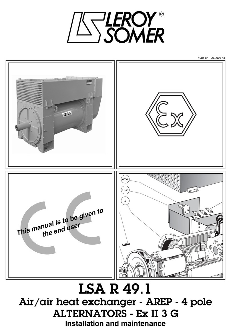
Leroy-Somer Nidec Mb 3101 User manual

frendeitptnlpl es
25
Référence 5062 -
Maintenance
Wartung
Mantenimiento
Manutenzione
Manutenção
Onderhoud
Konserwacja
2019.10 / c
Mb 3101, Mb 2000


Maintenance
Mb 3101, Mb 2000
2019.10 / c
fr
25
Référence 5062 fr -

2
Mb 3101, Mb 2000 - Maintenance
5062 fr - 2019.10 / c
Ce document vient en complément à la notice générale réf. 2557 (recommandations),
réf. 3711 (recommandations spéciques ATEX II 2D, II 3D) et à la notice installation réf. 2910.
NOTE
Nidec Leroy-Somer se réserve le droit de modier les caractéristiques de ses produits à tout moment pour y apporter les derniers
développements technologiques. Les informations contenues dans ce document sont donc susceptibles de changer sans avis
préalable. Nidec Leroy-Somer ne donne aucune garantie contractuelle quelle qu’elle soit en ce qui concerne les informations
publiées dans ce document et ne sera tenu pour responsable des erreurs qu’il peut contenir, ni des dommages occasionnés par
son utilisation.
ATTENTION
Les prescriptions, instructions et descriptions concernent l’exécution standard. Elles ne tiennent pas compte de variantes
de construction ou des adaptations spéciales. Le non respect de ces recommandations peut entraîner une détérioration
prématurée du réducteur et la non application de la garantie du constructeur.
Malgré tout le soin apporté à la fabrication et au contrôle de ce matériel, Nidec Leroy-Somer ne peut garantir à vie l’absence de
fuite de lubriant. Au cas où de légères fuites pourraient avoir des conséquences graves mettant en jeu la sécurité des biens et
des personnes, il appartient à l’installateur et à l’utilisateur de prendre toutes les précautions nécessaires pour éviter ces
conséquences.
SOMMAIRE
1 - COMMANDE DE PIÈCES ........................................................................................................3
2 - ENTRETIEN, VIDANGE ..........................................................................................................3
3 - VUES ÉCLATÉES, NOMENCLATURES .................................................................................3
3.1 - Kits arbre de sortie L ou R ou LR ................................................................................................................... 3
3.2 - Kit pattes ....................................................................................................................................................... 3
3.3 - Kit bras de réaction......................................................................................................................................... 3
3.4 - Vue éclatée Multibloc ..................................................................................................................................... 4
3.5 - Nomenclature Multibloc 3101, 22 à 26 ........................................................................................................... 4
3.6 - Nomenclature AP Mb 22 à Mb 26 ................................................................................................................... 4
3.7 - Nomenclature BAR Mb 22 à Mb 26 ................................................................................................................ 4
3.8 - Kit bride de sortie Mb 3101, Mb 22 à 25.......................................................................................................... 4
3.9 - Kit bride d’entrée Mb 22 à 26.......................................................................................................................... 4
3.10 - Pièces d’usure.............................................................................................................................................. 4
3.11 - Moteur LS (ES) : hauteur d’axe 71 à 132 ...................................................................................................... 5
4 - MB IA, IAW ..............................................................................................................................6
4.1 - Vue éclatée Mb IA 31, Mb IA 22 à MbIA 25 ..................................................................................................... 6
4.2 - Nomenclature Mb IA ...................................................................................................................................... 6
4.3 - Kit bras de réaction ........................................................................................................................................ 6
4.4 - Kit bras de réaction avec cassette d’étanchéité ............................................................................................. 6
4.5 - Kit cassette d’étanchéité ................................................................................................................................ 6
4.6 - Kit protection arbre creux ............................................................................................................................... 7
4.7 - Montage de l’arbre creux cylindrique avec l’arbre de la machine à entraîner ................................................. 7
4.8 - Moteur FLS (ES, IA, IAW) : hauteur d’axe 80 à 132 ........................................................................................ 8
Copyright 2019 : Moteurs Leroy-Somer. Ce document est la propriété de Moteurs Leroy-Somer. Il ne peut être reproduit sous quelque forme que ce soit sans notre
autorisation préalable. Marques, modèles et brevets déposés.
3
COMMANDE DE PIÈCES
Mb 3101, Mb 2000 - Maintenance
5062 fr - 2019.10 / c
fr
1 - COMMANDE DE PIÈCES
a) à prendre sur la plaque signalétique du réducteur :
Pour toute commande, indiquer s’il vous plaît :
1 - type du réducteur : 2401
2 - position de fonctionnement : V1
3 - forme : NU, NS, BSL, BDL
4 - réduction exacte : 40
5 - numéro de fabrication
6 - jeu : standard (Dynabloc)
- numéro, désignation de la pièce (pour l’arbre lent, préciser
les dimensions)
- le type, la polarité, la puissance et la bride FF (B5) ou FT
(B14) du moteur (voir plaques signalétiques).
N°
imin-1 :
MOTEURS LEROY-SOMER
DYNABLOC
Mb 2401 V1 BS L H MUFF
303257010 / 005 standard
40 75
321076
PAO ISO VG 460
4
5
1 2 3
6
min -1
501088
Mb 2401 V1 BS L H
PAG ISO VG 460
303257010 / 001
40 34,8
1523
4
i
N°
b) à prendre sur la nomenclature correspondante :
- repère et désignation de la pièce.
c) si moteur accouplé au réducteur, prendre sur plaque
signalétique moteur :
(pour moteur : voir notice correspondante)
- type moteur
- polarité (ou vitesse en min-1)
- puissance en kW
2 - ENTRETIEN, VIDANGE
Toutes les vis de xation doivent être serrées
jusqu’à 70 % de leur limite élastique.
Visite d’entretien préventif
- S’assurer dans le temps que les consignes d’installation
mécanique et électrique sont respectées.
- Si le réducteur en est équipé, s’assurer que le trou d’évent
du bouchon reniard n’est pas obstrué.
- Inspecter les joints.
- Nettoyer les grilles de ventilation du moteur.
- Contrôler l’entrefer des moteurs frein.
Vidange (Mb 22 à Mb 26xx)
Nous conseillons une vidange de l’huile PAO ISO VG 460,
selon la température de fonctionnement en continu :
70°C : 25 000 heures - 90°C : 6000 heures
80°C : 12 000 heures - 100°C : 3000 heures
- Changer les joints.
3 - VUES ÉCLATÉES,
NOMENCLATURES
3.1 - Kits arbre Mb 3101, Mb 22 à 26
Kit arbre de sortie L ou R
Rep. Désignation Qté
032 arbre lent 1
081 clavette de moyeu 1
082 clavette client 1
199 vis de maintien de l’arbre 1
200 rondelle plate 1
201 vis de bout d’arbre 1
203 rondelle plate 1
Kit arbre de sortie LR
Rep. Désignation Qté
032 arbre lent 1
081 clavette de moyeu 1
082-3 clavettes 2
199 vis d’arrêt 2
200 bague d’arrêt 1
201-2 vis de bout d’arbre 2
203-4 rondelle plate 2
3.2 - Kit pattes Mb 22 à 26
Rep. Désignation Qté
018 socle à pattes 1
197 vis de xation 4
198 rondelles plates 4
3.3 - Kit bras de réaction
Mb 31, Mb 22 à 25
Rep. Désignation Qté
017 bras de réaction 1
195 vis de xation 4
MONTAGE DU BRAS DE RÉACTION
Le bras de réaction (17) sera xé sur le carter par les 4 trous
de la face latérale choisie au moyen de vis (195) type CHc de
classe 8.8 minimum (selon NFE 27-005).
Ces quatre vis doivent être freinées par un adhésif anaérobie
(Loctite Freinlet normal 243 par exemple) qui devra résister
aux sollicitations vibratoires tout en permettant le démontage
des vis si nécessaire.
Moment de serrage des vis de xation
Le serrage se fera progressivement et simultanément sur les
quatre vis (serrage en croix).

4
VUES ÉCLATÉES, NOMENCLATURES
Mb 3101, Mb 2000 - Maintenance
5062 fr - 2019.10 / c
3.4 - Vue éclatée Multibloc
3.5 - Nomenclature Multibloc 3101, 22 à 26
Rep. Désignation Qté Rep. Désignation Qté Rep. Désignation Qté
001 carter 1 092 joint droit 1 135 circlips I 1
005/006 palier pour Mb 26 2 093 joint en entrée 1 137 rondelle (Mb 25-26) 1
010 capot protection arbre creux 1 095/096 joint torique (Mb 26) 2 139 cales de réglage (Mb 25-26) 1 jeu
041 vis sans n 1119 circlips I gauche 1 171/172 vis xation de 005/006 (Mb 25-26) 8
051 roue en bronze 1 120 circlips I droit (Mb 22 à 26) 1 180 vis xation capot (010) 4
061 roulement gauche 1 121 rondelle gauche (Mb 22 à 26) 1 212 entretoise (Mb 31) 1
062 roulement droit 1 122 rondelle droite (Mb 22 à 26) 1 253 bouchon obturateur 1
063 roulement en entrée 1 123/124 cales de réglage (Mb 22 à 26) 1 255 bouchon reniard 1
064 roulement avant 1 127 circlips E (Mb 22 à 24) 1 ou 2 257 bouchon huile 2 à 4
086 clavette (Mb 31) 1 128 circlips E (Mb 22 à 26) 1 ou 2
091 joint gauche 1 129 rondelle d’appui (Mb 25-26) 1
3.6 - Nomenclature “AP”1Mb 22 à 26
Rep. Désignation Qté
041 vis AP 1
084 clavette AP 4
205 vis de bout d’arbre 4
207 rondelle de bout d’arbre 1
1. Arbre primaire
3.7 - Nomenclature “BAR”2Mb 22 à 26
Rep. Désignation Qté
041 vis avec BAR 1
085 clavette BAR 4
094 joint 4
206 vis de bout d’arbre 4
208 rondelle de bout d’arbre 4
2. Bout d’arbre rapide
3.8 - Kit bride de sortie Mb 3101, Mb 22 à 25
Rep. Désignation Qté
007 bride gauche 1
175 vis de xation 4
177 rondelle frein 4
008 bride droite 1
176 vis de xation 4
178 rondelle frein 4
3.9 - Kit bride d’entrée Mb 22 à 26
Rep. Désignation Qté
013 bride pour moteur 1
187 vis de xation 4
189 rondelle frein 4
209 vis de xation moteur 4
210 rondelle 4
3.10 - Pièces d’usure (roulement et joint)
Taille Mb standard AP standard
061-062 063 064 063 064 093 094 (BAR) 091-092
2601 6213 3211* 6305 3211* 6305 AS 55x100x13 A 25x62x10 AS 65x85x13
2501 6018 3210* 6304 2RS 3210* 6304 2RS AS 50x90x8 A 20x52x7 AS 90x140x13
2401 6212 6209 ZZ 6303 2RS 3209 2RS 6303 2RS AS 45x85x8 A 17x47x7 AS 60x110x13
2301 6012 6207 ZZ 6203 2RS 3207 2RS 6203 2RS AS 35x72x7 A 17x40x7 AS 60x95x10
2201 6208 6206 ZZ 6301 2RS 3206 2RS 6301 2RS AS 30x62x7 A 12x37x7 AS 40x80x10
3101 --------
*Sans encoche de remplissage
Variantes : “AP”1“BAR”2“Mb 26”

5
VUES ÉCLATÉES, NOMENCLATURES
Mb 3101, Mb 2000 - Maintenance
5062 fr - 2019.10 / c
fr
3.11 - Moteur LS(ES) : hauteur d’axe 71 à 132
Rep. Désignation Qté Rep. Désignation Qté Rep. Désignation Qté
001 Stator bobiné 1 021 Clavette de bout d’arbre 1 060 Segment d’arrêt (circlips) 1
002 Carter 1 026 Plaque signalétique 1 071 Boîte à bornes 1
003 Rotor 1 027 Vis de xation du capot 4 078 Presse-étoupe 1
005 Flasque côté accouplement 1 030 Roulement côté accouplement 1 084 Planchette à bornes 1
006 Flasque arrière 1 039 Joint côté accouplement 1 085 Vis de planchette 1
007 Ventilateur 1 050 Roulement arrière 1 098 Barrettes de connexions 1
013 Capot de ventilation 1 054 joint arrière 1 1
014 Tiges de montage 4 059 Rondelle de précharge 1 1
98
5
13
7
14
85
54
6
84
26
2
1
60
59
50
27
3
30
21
71
78
39
IM B5
IM B14

6
MB IA, IAW
Mb 3101, Mb 2000 - Maintenance
5062 fr - 2019.10 / c
4 - Mb IA, IAW
Pour l’utilisation dans l’industrie Agro-alimentaire, nous
livrons des réducteurs conformes à la directive machine
89/392/CEE et répondant aux exigences posées par l’USDA
(United States Department of Agriculture) avec option PAO
H1 : lubriant pouvant entrer en contact fortuit avec les
aliments. Ils sont peints en blanc RAL 9010 et conditionnés
dans des emballages étudiés pour résister à des conditions
normales de transport et de stockage. Éviter toute
manœuvre brusque.
Identication :
1 - type de réducteur : Mb IA 2401
2 - position de fonctionnement : B5
3 - forme de xation : NU, H arbre de sortie creux
4 - réduction exacte : 40
5 - numéro de fabrication : 303257020/001
6 - lubriant
N°
imin-1
MOTEURS
LEROY-SOMER
Mb IA 2401 B5 NU H MUFT
303257020 / 001
40 34,8
501088
PAO ISO VG 460 H1
1
46
5
2 3
4.1 - Vue éclatée Mb IA 31, Mb IA 22 à Mb IA 25
195
017
139
137
129
212
086
258
222
220
215
182
180
098
010
181
179
199
097
095
009
260
257
256 255
253
135
128
127
123
124
121
122
119
120
093
091
092 064
063
061
062 051
041
001
4.2 - Nomenclature Mb IA
Rep. Désignation Qté Rep. Désignation Qté Rep. Désignation Qté Rep. Désignation Qté
001 carter 1 064 roulement avant 1 121 rondelle gauche
(Mb iA 22 à 25) 1 137 rondelle (Mb iA 25) 1
010 capot protection arbre
creux 1 086 clavette (Mb iA 31) 1 122 rondelle droite
(Mb iA 22 à 25) 1 139 cales de réglage
(Mb iA 25) 1 jeu
041 vis sans n 1 091 joint gauche 1 123/124 cales de réglage
(Mb iA 22 à 25) 8/6 180 vis inox xation capot
(010) 4
051 roue en bronze 1 092 joint droit 1 127 circlips E (Mb iA 22 à 24) 1 ou 2 212 entretoise (Mb iA 31) 1
061 roulement gauche 1 093 joint en entrée 1 128 circlips E (Mb iA 22 à 25) 1 ou 2 253 bouchon obturateur 1
062 roulement droit 1 119 circlips I gauche 1 129 rondelle d’appui (Mb iA 25) 1 255 bouchon reniard 1
063 roulement en entrée 1 120 circlips I droit (Mb iA 22 à 25) 1 135 circlips I 1 256/257 bouchon huile 3
4.3 - Kit bras de réaction
Rep. Désignation Qté
017 bras de réaction 1
195 vis de xation inox 4
4.4 - Kit bras de réaction avec cassette d’étanchéité
Mb IA 31, Mb IA 22 à Mb IA 25
Rep. Désignation Qté
009 chapeau support de joint 1
017 bras de réaction 1
095 joint torique 1
097 joint cassette 1
195 vis de xation inox 4
Montage du bras de réaction : voir réf. 2910 § 4.1.
4.5 - Kit cassette d’étanchéité
Rep. Désignation Qté
009 chapeau support de joint 1
095 joint torique 1
097 joint cassette 1
179 vis xation inox 1
181 rondelle inox 4

7
MB IA, IAW
Mb 3101, Mb 2000 - Maintenance
5062 fr - 2019.10 / c
fr
4.6 - Kit protection arbre creux
Rep. Désignation Qté
010 capot protection arbre creux 1
098 joint 1
180 vis inox xation capot (010) 4
182 rondelles inox 4
199 vis inox 1
215 rondelle 4
220 circlips 2
222 rondelle 1
258 bouchon de protection 1
999 contenant de graisse 1
Montage de la protection arbre creux :
Placer le joint (rep. 098) sur le capot de protection (rep. 010) ;
xer l’ensemble sur le carter par les 4 trous de la face latérale
choisie au moyen des vis (rep. 180) sans oublier les rondelles
(rep. 182) an de ne pas écailler la peinture.
4.7 - Montage de l’arbre creux cylindrique avec
l’arbre de la machine à entraîner
F
GA
D
Type
Arbre de sortie
creux Arbre client
Ø DH7 F GA Ø Dg6 Longueur L Rep. 0971Taraudage
Mini Maxi ØJC L1 O Z
Mb 2601 50 14 53,8 50 - - - - - -
Mb 2501 45 14 48,8 45 130 132 56 h8 25 M16 36
Mb 2401 35 10 38,3 35 105 109 45 h8 25 M12 28
Mb 2301 30 8 33,3 30 90 93 35 h8 21 M10 22
Mb 2201 25 8 28,3 25 85 90 35 h8 20 M10 22
Mb 3101 20 6 22,8 20 70 72 25 h8 17 M6 16
1. Ø joint cassette (rep. 097)
1 - S’assurer que l’arbre cylindrique est usiné suivant la
norme NF - E 22 - 175, avec un ajustement glissant : g6,
(le moyeu est : H7).
2 - S’assurer que la clavette est normalisée et l’arbre d’une
longueur minimum L (voir tableau ci-dessus) taraudé en
bout (O.Z).
3 - Avant le montage, dégraisser toutes les pièces, en
prenant soin de ne pas projeter de solvant sur les joints.
Effectuer une légère lubrication (pâte PAO) à l’aide du
contenant fourni (rep. 999), des pièces en contact, de
manière à éviter la corrosion.
Montage :
Le montage doit s’effectuer sans choc, selon la procédure
ci-dessus.
Le réducteur Mb IA est monté sur l’arbre de la machine à
l’aide d’une tige letée, vissée dans l’arbre.
En vissant l’écrou qui prend appui sur la rondelle (rep. 222),
l’arbre est inséré dans le moyeu cylindrique du Mb IA sans
à-coup.
Fermer avec la vis (rep. 199).
Démontage :
Prendre une vis dont le diamètre correspond au taraudage
de la rondelle (rep. 222) et visser pour extraire l’arbre.
Fixation sur arbre épaulé :
Fixation sur arbre lisse :
Joint torique
Joint torique
Joint torique
Joint torique

8
MB IA, IAW
Mb 3101, Mb 2000 - Maintenance
5062 fr - 2019.10 / c
4.8 - Moteur FLS(ES, IA, IAW) : hauteur d’axe 80 à 132
Rep. Désignation Qté Rep. Désignation Qté Rep. Désignation Qté
001 Stator bobiné 1 022 Rondelle de bout d’arbre 1 059 Rondelle de précharge 1
002 Carter 1 023 Vis de bout d’arbre 1 060 Segment d’arrêt 1
003 Rotor 1 026 Plaque signalétique 1 071 Boîte à bornes 1
005 Flasque côté accouplement (DE) 1 030 Roulement côté accouplement 1 078 Presse étoupe 1
006 Flasque arrière (NDE) 1 039 Joint côté accouplement 1 084 Planchette à bornes 1
014 Tiges de montage 4 050 Roulement arrière 1 308 Chicane 1
021 Clavette de bout d’arbre 1 054 Joint arrière 1
Nota : La représentation des pièces ci-dessus ne prégure pas des détails, formes et volumes de celles-ci.
78
3
5
5
IM B14
IM B5
14
54
6
26
2
1
60
30
59
50
71
39
22
308
23
84
21
60
30
39

Maintenance
Mb 3101, Mb 2000
25
Référence 5062 en - 2019.10 / c
en

10
Mb 3101, Mb 2000 - Maintenance
5062 en - 2019.10 / c
This document complements the general instructions ref. 2557 (recommendations),
ref. 3711 (ATEX II 2D, II 3D specic recommendations) and the installation instructions ref. 2910.
NOTE
Nidec Leroy-Somer reserves the right to modify the characteristics of its products at any time in order to incorporate the lastest
technological developments. The information contained in this document may therefore be changed without notice.
Nidec Leroy-Somer gives no contractual guarantee whatsoever concerning the information published in this document and cannot
be held responsible for any errors it may contain, nor for any damage resulting from ist use.
CAUTION
The specications, instructions and descriptions are for standard operation. They do not take account of structural
variants or special adaptations. Failure to comply with these recommendations may lead to premature deterioration of
the gearbox and voiding of the manufacturer’s guarantee.
Despite all the care taken in the manufacture and checking of this equipment, Nidec Leroy-Somer cannot guarantee that lubricant
will not escape during the product’s lifetime. If slight leaks could have serious consequences for the safety of people and property,
the installer and user should take all necessary precautions to avoid such consequences.
CONTENTS
1 - HOW TO ORDER ...................................................................................................................11
2 - MAINTENANCE, OIL CHANGE ............................................................................................11
3 - EXPLODED VIEWS, PARTS LISTS ......................................................................................11
3.1 - Output shaft kits L or R or LR ....................................................................................................................... 11
3.2 - Foot mounting kit ......................................................................................................................................... 11
3.3 - Torque arm kit .............................................................................................................................................. 11
3.4 - Exploded view of Multibloc........................................................................................................................... 12
3.5 - Parts list for Multibloc 3101, 22 to 26............................................................................................................ 12
3.6 - Parts list for AP Mb 22 to Mb 26.................................................................................................................... 12
3.7 - Parts list for BAR Mb 22 to Mb 26................................................................................................................. 12
3.8 - Output ange kit Mb 3101, Mb 22 to 25........................................................................................................ 12
3.9 - Input ange kit Mb 22 to 26 .......................................................................................................................... 12
3.10 - Primary maintenance parts........................................................................................................................ 12
3.11 - LS (ES) motor: frame size 71 to 132........................................................................................................... 13
4 - Mb ia, IAW .............................................................................................................................14
4.1 - Exploded view of Mb IA 31, Mb IA 22 to MbIA 25 ......................................................................................... 14
4.2 - Parts list for Mb IA ....................................................................................................................................... 14
4.3 - Torque arm kit ............................................................................................................................................. 14
4.4 - Torque arm kit with sealing cartridge ........................................................................................................... 14
4.5 - Sealing cartridge kit .................................................................................................................................... 14
4.6 - Hollow shaft protection kit ........................................................................................................................... 15
4.7 - Mounting the cylindrical hollow shaft with the shaft of the driven machine .................................................. 15
4.8 - FLS (ES, IA, IAW) motor: frame size 80 to 132 ............................................................................................ 16
Copyright 2019 : Moteurs Leroy-Somer. This document is the property of Moteurs Leroy-Somer. It cannot be reproduced in any form without prior authorisation. All
brand names are registered trademarks.

11
HOW TO ORDER
Mb 3101, Mb 2000 - Maintenance
5062 en - 2019.10 / c
en
1 - HOW TO ORDER
a) from the gearbox nameplate :
When ordering, please indicate:
1 - gearbox type: 2401
2 - operating position: V1
3 - form: NU, NS, BSL, BDL
4 - exact reduction: 40
5 - manufacturing number
6 - play: standard (Dynabloc)
- number and description of spare part (for the slow speed
shaft, please specify the dimensions)
- type, number of poles, power and FF (B5) or FT (B14)
ange of the motor (refer to the nameplates).
N°
imin-1 :
MOTEURS LEROY-SOMER
DYNABLOC
Mb 2401 V1 BS L H MUFF
303257010 / 005 standard
40 75
321076
PAO ISO VG 460
4
5
1 2 3
6
min -1
501088
Mb 2401 V1 BS L H
PAG ISO VG 460
303257010 / 001
40 34,8
1523
4
i
N°
b) from the appropriate part list:
- part description and item number.
c) where a motor is tted to the gearbox, from the motor
nameplate:
(for the motor : see the corresponding manual)
- motor type
- No. of poles (or speed in min-1)
- power in kW
2 - MAINTENANCE, OIL CHANGE
All the xing screws must be tightened up to 70%
of their yield strength.
Preventive maintenance visit
- Check regularly that the recommendations concerning
mechanical and electrical installation are still complied with.
- Lubrication: refer to corresponding documents.
- If the gearbox is tted with a breather plug, make sure that
the vent hole of the plug is not obstructed.
- Inspect the seals.
- Clean the ventilation louvres of the motor.
- Control the air gap of brake motors.
Oil change (Mb 22 to Mb 26xx)
We recommend that the PAO ISO VG 460 oil is changed
according to the operating temperature in continuous
operation:
70°C: 25.000 hours - 90°C: 6.000 hours
80°C: 12.000 hours - 100°C: 3.000 hours
- Change the seals.
3 - EXPLODED VIEWS, PARTS LISTS
3.1 - Shaft kits Mb 3101, Mb 22 to 26
Output ange kit L or R
Ref. Description Qty
032 slow speed shaft 1
081 hub key 1
082 client key 1
199 shaft retaining screw 1
200 washer 1
201 shaft extension screw 1
203 washer 1
Output ange kit LR
Ref. Description Qty
032 slow speed shaft 1
081 hub key 1
082-3 keys 2
199 stop screw 2
200 locking collar 1
201-2 shaft extension screw 2
203-4 washer 2
3.2 - Foot mounting kit for
Mb 22 to 26
Ref. Description Qty
018 foot plate 1
197 xing screws 4
198 washers 4
3.3 - Torque arm kit for Mb
31, Mb 22 to 25
Ref. Description Qty
017 torque arm 1
195 xing screws 4
MOUNTING THE TORQUE ARM
The torque arm (17) should be xed onto the frame using the
4 holes on the chosen side with cheese head screws (195)
class 8.8 minimum (according to NFE 27-005).
These four screws should be locked with an anaerobic
adhesive (Loctite 243 Removable Threadlocker for example)
which should resist vibrations but still allow the screws to be
removed if necessary.
Tightening torque of xing screws
All four screws should be tightened gradually and
simultaneously.

12
EXPLODED VIEWS, PARTS LISTS
Mb 3101, Mb 2000 - Maintenance
5062 en - 2019.10 / c
3.4 - Exploded view of Multibloc
3.6 - Parts list for “AP”1Mb 22 to 26
Ref. Description Qty
041 AP screw 1
084 AP key 4
205 shaft extension screw 4
207 shaft extension washer 1
1. Input shaft
3.7 - Parts list for “BAR”2Mb 22 to 26
Ref. Description Qty
041 high speed shaft screw 1
085 high speed shaft key 4
094 seal 4
206 shaft extension screw 4
208 shaft extension washer 4
2. High speed shaft
3.8 - Output ange kit Mb 3101, Mb 22 to 25
Ref. Description Qty
007 ange (left side) 1
175 xing screws 4
177 lock washer 4
008 ange (right side) 1
176 xing screws 4
178 lock washer 4
3.9 - Input ange kit Mb 22 to 26
Ref. Description Qty
013 ange for motor 1
187 xing screws 4
189 lock washer 4
209 motor xing screws 4
210 washer 4
3.10 - Primary maintenance parts (bearing and seal)
Mb size standard AP standard
061-062 063 064 063 064 093 094 (BAR) 091-092
2601 6213 3211* 6305 3211* 6305 AS 55x100x13 A 25x62x10 AS 65x85x13
2501 6018 3210* 6304 2RS 3210* 6304 2RS AS 50x90x8 A 20x52x7 AS 90x140x13
2401 6212 6209 ZZ 6303 2RS 3209 2RS 6303 2RS AS 45x85x8 A 17x47x7 AS 60x110x13
2301 6012 6207 ZZ 6203 2RS 3207 2RS 6203 2RS AS 35x72x7 A 17x40x7 AS 60x95x10
2201 6208 6206 ZZ 6301 2RS 3206 2RS 6301 2RS AS 30x62x7 A 12x37x7 AS 40x80x10
3101 --------
*Without lling slot
Versions: “AP”1“BAR”2“Mb 26”
3.5 - Parts list for Multibloc 3101, 22 to 26
Ref. Description Qty Ref. Description Qty Ref. Description Qty
001 frame 1 092 seal (right side) 1 135 I circlip 1
005/006 end shield for Mb 26 2 093 input seal 1 137 washer (Mb 25-26) 1
010 hollow shaft protective cover 1 095/096 O ring seal (Mb 26) 2 139 adjusting shims (Mb 25-26) 1 set
041 worm 1 119 I circlip (left side) 1 171/172 screws for 005/006 (Mb 25-26) 8
051 bronze wheel 1 120 I circlip (right side) (Mb 22 to 26) 1 180 cover xing screw (010) 4
061 bearing (left side) 1 121 washer (left side) (Mb 22 to 26) 1 212 spacer (Mb 31) 1
062 bearing (right side) 1 122 washer (right side) (Mb 22 to 26) 1 253 blanking plug 1
063 input bearing 1 123/124 adjusting shims (Mb 22 to 26) 1 255 breather plug 1
064 DE bearing 1 127 E circlip (Mb 22 to 24) 1 or 2 257 oil plug 2 to 4
086 key (Mb 31) 1 128 E circlip (Mb 22 to 26) 1 or 2
091 seal (left side) 1 129 cable gland washer (Mb 25-26) 1

13
EXPLODED VIEWS, PARTS LISTS
Mb 3101, Mb 2000 - Maintenance
5062 en - 2019.10 / c
en
3.11 - LS(ES) motor: frame size 71 to 132
Ref. Description Qty Ref. Description Qty Ref. Description Qty
001 Wound stator 1 021 Shaft extension key 1 060 Circlip 1
002 Frame 1 026 Nameplate 1 071 Terminal box 1
003 Rotor 1 027 Fan cover screw 4 078 Cable gland 1
005 DE shield 1 030 Drive end bearing 1 084 Terminal block 1
006 NDE shield 1 039 Drive end seal 1 085 Set screw 1
007 Fan 1 050 Non drive end bearing 1 098 Connectors 1
013 Fan cover 1 054 Non drive end seal 1 1
014 Tie rods 4 059 Preloading (wavy) washer 1 1
98
5
13
7
14
85
54
6
84
26
2
1
60
59
50
27
3
30
21
71
78
39
IM B5
IM B14

14
MB IA, IAW
Mb 3101, Mb 2000 - Maintenance
5062 en - 2019.10 / c
4 - Mb IA, IAW
For applications in the food processing industry, we supply
gearboxes conforming to the machinery directive 89/392/
EEC and complying with the requirements of the USDA
(United States Department of Agriculture) with the PAO H1
option: lubricant which can come into accidental contact with
food.
They are painted in white RAL 9010 and wrapped in specially
designed packaging to withstand normal transport and
storage conditions. Avoid any abrupt movements.
Identication :
1 - gearbox type: Mb IA 2401
2 - operating position: B5
3 - mounting form: NU, Hhollow output shaft
4 - exact reduction: 40
5 - manufacturing number: 303257020/001
6 - lubricant
N°
imin-1
MOTEURS
LEROY-SOMER
Mb IA 2401 B5 NU H MUFT
303257020 / 001
40 34,8
501088
PAO ISO VG 460 H1
1
46
5
2 3
4.2 - Mb IA parts list
Ref. Description Qty Ref. Description Qty Ref. Description Qty Ref. Description Qty
001 frame 1 064 DE bearing 1 121 washer (left side)
(Mb iA 22 to 25) 1 137 washer (Mb iA 25) 1
010 hollow shaft
protective cover 1 086 key (Mb iA 31) 1 122 washer (right side)
(Mb iA 22 to 25) 1 139 adjusting shims
(Mb iA 25) 1 set
041 worm 1 091 seal (left side) 1 123/124 adjusting shims
(Mb iA 22 to 25) 8/6 180 st. steel cover xing
screw (010) 4
051 bronze wheel 1 092 seal (right side) 1 127 E circlip (Mb iA 22 to 24) 1 ou 2 212 spacer (Mb iA 31) 1
061 bearing (left side) 1 093 input seal 1 128 E circlip (Mb iA 22 to 25) 1 ou 2 253 blanking plug 1
062 bearing (right side) 1 119 I circlip (left side) 1 129 cable gland washer (Mb iA 25) 1 255 breather plug 1
063 input bearing 1 120 I circlip (right side) (Mb iA 22 to 25) 1 135 I circlip 1256/257 oil plug 3
4.3 - Torque arm kit
Ref. Description Qty
017 torque arm 1
195 st. steel xing screws 4
4.4 - Torque arm kit with sealing cartridge
Mb IA 31, Mb IA 22 to Mb IA 25
Ref. Description Qty
009 seal retainer 1
017 torque arm 1
095 O ring seal 1
097 cartridge seal 1
195 st. steel xing screw 4
Mounting the torque arm: see ref. 2910 § 4.1.
4.5 - Sealing cartridge kit
Ref. Description Qty
009 seal retainer 1
095 O ring seal 1
097 cartridge seal 1
179 st. steel xing screw 1
181 st. steel washer 4
4.1 - Exploded view of Mb IA 31, Mb IA 22 to Mb IA 25
195
017
139
137
129
212
086
258
222
220
215
182
180
098
010
181
179
199
097
095
009
260
257
256 255
253
135
128
127
123
124
121
122
119
120
093
091
092 064
063
061
062 051
041
001

15
MB IA, IAW
Mb 3101, Mb 2000 - Maintenance
5062 en - 2019.10 / c
en
4.6 -
Hollow shaft protection kit
Ref. Description Qty
010 hollow shaft protective cover 1
098 seal 1
180 st. steel cover xing screw (010) 4
182 st. steel washers 4
199 st. steel screw 1
215 washer 4
220 circlip 2
222 washer 1
258 protective cap 1
999 tub of grease 1
Mounting the hollow shaft protection:
Place the seal (ref. 098) on the protective cover (ref. 010) and
x them on the frame using the 4 holes on the chosen side
with
the screws (ref. 180), not forgetting the washers (ref. 182), to
avoid scratching the paint.
4.7 - Mounting the cylindrical hollow shaft with
the shaft of the driven machine
F
GA
D
Type
Hollow output
shaft Client shaft
Ø DH7 F GA Ø Dg6 Length L Ref. 0971Thread
Min. Max. ØJC L1 O Z
Mb 2601 50 14 53.8 50 - - - - - -
Mb 2501 45 14 48.8 45 130 132 56 h8 25 M16 36
Mb 2401 35 10 38.3 35 105 109 45 h8 25 M12 28
Mb 2301 30 8 33.3 30 90 93 35 h8 21 M10 22
Mb 2201 25 8 28.3 25 85 90 35 h8 20 M10 22
Mb 3101 20 6 22.8 20 70 72 25 h8 17 M6 16
1. Cartridge seal Ø (ref. 097)
1 - Check that the cylindrical shaft has been machined in
accordance with standard NF - E 22 - 175, with a slide t:
g6, (the hub is: H7).
2 - Check that the key is standard and the shaft is the
minimum length L (see above table) tapped at the end
(O.Z).
3 - Before mounting, degrease all the parts, taking care not
to splash any solvent on the seals. Use the supplied jar
of grease (PAO compound) (ref. 999) to lubricate any
parts in contact, to avoid corrosion.
Mounting:
Mounting should be performed as described in the procedure
above, without jolting.
The Mb IA gearbox is mounted on the machine shaft using a
threaded rod, screwed into the shaft.
By screwing the nut down onto the washer (ref. 222), the
shaft
is smoothly inserted into the cylindrical hub of the Mb IA.
Tighten with the screw (ref. 199).
Dismantling:
Use a spanner with a diameter corresponding to the washer
thread (ref. 222) and turn the screw until the shaft comes out.
Fixing on a shouldered shaft:
Fixing on an untapped shaft:
O ring seal
O ring seal
O ring seal
O ring seal

16
MB IA, IAW
Mb 3101, Mb 2000 - Maintenance
5062 en - 2019.10 / c
4.8 - FLS(ES, IA, IAW) motor: frame size 80 to 132
Ref. Description Qty Ref. Description Qty Ref. Description Qty
001 Wound stator 1 022 Shaft extension washer 1 059 Preloading (wavy) washer 1
002 Frame 1 023 Shaft extension screw 1 060 Circlip 1
003 Rotor 1 026 Nameplate 1 071 Terminal box 1
005 Drive end shield (DE) 1 030 Drive end bearing 1 078 Cable gland 1
006 Non-drive end shield (NDE) 1 039 Drive end seal 1 084 Terminal block 1
014 Tie rods 4 050 Non drive end bearing 1 308 Labyrinth seal 1
021 Shaft extension key 1 054 Non drive end seal 1
Note: The above illustration of parts does not necessarily show details, forms and volumes accurately.
78
3
5
5
IM B14
IM B5
14
54
6
26
2
1
60
30
59
50
71
39
22
308
23
84
21
60
30
39

Wartung
Mb 3101, Mb 2000
25
Référence 5062 de - 2019.10 / c
de

18
Mb 3101, Mb 2000 - Wartung
5062 de - 2019.10 / c
Dieses Dokument ist eine Ergänzung zu der allgemeinen Handbuch Ref. 2557 (Empfehlungen),
Ref. 3711 (spezische Empfehlungen ATEX II 2D, II 3D) und zu der Inbetriebnahme Handbuch Ref. 2910.
ANMERKUNG
Nidec Moteurs Leroy-Somer behält sich das Recht vor, die technischen Daten seiner Produkte jederzeit zu ändern, um so den
neuesten technologischen Erkenntnissen und Entwicklungen Rechnung tragen zu können. Die in diesem Handbuch enthaltenen
Informationen können daher ohne vorherige Ankündigung geändert werden.
Moteurs Leroy-Somer übernimmt keinerlei Garantie für die Richtigkeit der in diesem Handbuch enthaltenen Informationen.
Schäden, die aufgrund unrichtiger Angaben in diesem Handbuch entstehen, unterliegen nicht der Gewährleistungspicht.
ACHTUNG
Die Vorschriften, Anweisungen und Beschreibungen beziehen sich auf die Standardausführung.
Sonderausführungen oder Konstruktionsvarianten werden nicht berücksichtigt. Das Nichtbeachten dieser
Empfehlungen kann zu vorzeitigem Verschleiß das Getriebe und dem Erlöschen der Herstellergarantie führen.
Trotz sorgfältigster Überwachung von Fertigung und Kontrolle des beschriebenen Getriebes kann Nidec Moteurs Leroy-Somer
nicht auf Lebensdauer garantieren, dass keine Leckagen des Schmiermittels auftreten. Bei Anwendungen, bei denen ein leichtes
Austreten von Schmiermittel schwerwiegende Folgen für die Sicherheit von Gegenständen und Personen haben könnte, obliegt
es dem Installateur und dem Betreiber, alle notwendigen Vorkehrungen zur Vermeidung dieser Folgen zu treffen.
INHALTSVERZEICHNIS
1 - BESTELLUNG VON ERSATZTEILEN ..................................................................................19
2 - WARTUNG, ÖLWECHSEL ....................................................................................................19
3 - EXPLOSIONSZEICHNUNGEN, ERSATZTEILLISTEN .........................................................19
3.1 - Montagesätze Abtriebswelle L oder R oder LR ............................................................................................ 19
3.2 - Montagesatz Fußausführung ...................................................................................................................... 19
3.3 - Montagesatz Drehmomentstütze................................................................................................................. 19
3.4 - Explosionszeichnung Multibloc.................................................................................................................... 20
3.5 - Teileverzeichnis Multibloc 3101, 22 bis 26 ................................................................................................... 20
3.6 - Teileverzeichnis AP Mb 22 bis Mb 26 ........................................................................................................... 20
3.7 - Teileverzeichnis BAR Mb 22 bis Mb 26 ........................................................................................................ 20
3.8 - Montagesatz Abtriebsansch Mb 3101, Mb 22 bis 25 .................................................................................. 20
3.9 - Montagesatz Eintriebsansch Mb 22 bis 26................................................................................................. 20
3.10 - Verschleißteile ........................................................................................................................................... 20
3.11 - Motor LS (ES) : Baugröße 71 bis 132 ......................................................................................................... 21
4 - MB IA, IAW ............................................................................................................................22
4.1 - Explosionszeichnung Mb IA 31, Mb IA 22 bis MbIA 25 ................................................................................. 22
4.2 - Teileverzeichnis Mb IA ................................................................................................................................. 22
4.3 - Montagesatz Drehmomentstütze ................................................................................................................ 22
4.4 - Montagesatz Drehmomentstütze mit Kassette zum Herstellen der Dichtigkeit ............................................ 22
4.5 - Montagesatz Kassette zum Herstellen der Dichtigkeit ................................................................................ 22
4.6 - Montagesatz Abdeckhaube Hohlwelle ......................................................................................................... 23
4.7 - Montage der zylindrischen Hohlwelle an die Welle der anzutreibenden Maschine ...................................... 23
4.8 - Motor FLS (ES, IA, IAW) : Baugröße 80 bis 132........................................................................................... 24
Copyright 2019 : Moteurs Leroy-Somer. Dieses Dokument ist Eigentum von Moteurs Leroy-Somer. Ohne vorherige Genehmigung darf es in keiner Weise reproduziert
werden. Marken, Muster und Patente geschützt.
This manual suits for next models
1
Table of contents
Languages:
Other Leroy-Somer Industrial Equipment manuals

Leroy-Somer
Leroy-Somer LSA 35 Instruction Manual

Leroy-Somer
Leroy-Somer unidrive sp Guide

Leroy-Somer
Leroy-Somer LSA 46.2 Instruction Manual

Leroy-Somer
Leroy-Somer LSA 47.2 Instruction Manual

Leroy-Somer
Leroy-Somer LSA 35 Instruction Manual

Leroy-Somer
Leroy-Somer LSA 49.1 Instruction Manual

Leroy-Somer
Leroy-Somer Nidec LSAH 42.3 Instruction Manual

Leroy-Somer
Leroy-Somer LSA VS 40 Instruction Manual

Leroy-Somer
Leroy-Somer LSA R 49.1 Instruction Manual

Leroy-Somer
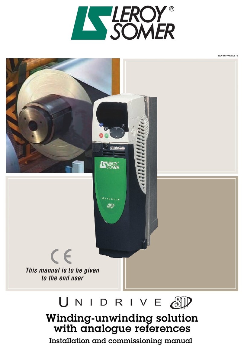
Leroy-Somer Nidec LSAP 40 POLE Instruction Manual