manuals.online logo
Brands
  1. Home
  2. •
  3. Brands
  4. •
  5. Alfa Network
  6. •
  7. Industrial Equipment
  8. •
  9. Alfa Network CR6 Operation instructions

Alfa Network CR6 Operation instructions

HMI Manual
ORIGINAL INSTRUCTION
Codice:
Anno:
2022
Rev.:
01
www.alfadispenser.com
CR6/CR4
HMI Manual –CR6
2
EN
Alfa Srl
Via Caduti di Ustica, 28 - Calderara di Reno
40012 BOLOGNA –Italy
Tel +39 051 0828494 Fax +39 051 0823283
© Copyright 2021 Tutti i diritti riservati
© Copyright 2021 All rights reserved
Total or partial reproduction, modification and translation of the present manual is forbidden without previous
authorisation of Alfa Srl.
IMPORTANT:
Alfa Srl will be not liable for technical or editorial errors or omissions contained herein
IMPORTANT:
Alfa Srl cannot be held responsible for any errors or damage caused by the use of supplies or spare parts not specifically
approved or guaranteed by Alfa Srl.
HMI Manual –CR6
EN
INSTALLATION
3
HOME PAGE
The machine is equipped with a touch display used as HMI
(Human Machine Interface) by the operator, on which the
machine software runs. The figure on the right shows the
home page of the HMI.
The HMI home page always shows the status of every single
head (1). Each dispensing head can show the following statuses:
STANDBY: machine ready, waiting for commands
DISPENSING: dispensing in progress
RESET: reset in progress
ALARM: machine error
DIAGNOSTIC: machine waiting for manual commands
ROTATING: colorant circuit positioning (only for refill operations)
JAR POSITIONING: movement of roller conveyors and lifters
When the machine is switched on, the system runs a reset routine and sets all dispensing heads to STANDBY.
Below the list of the main buttons/images and their meaning:
The name of the dispensing heads are represented in the
pictures on the right. The software uses references in letters
and numbers to identify each dispensing head.
Button/image
Description
Start production after placing shuttle on the roller conveyor
Finish production by eject shuttle
Access manual commands for each part of the machine
Inactive photocell
HMI Manual –CR6
4
INSTALLATION
EN
At the bottom of each page we found the following tool bar with the following buttons:
Machine automation working (Carousel ok) AND active photocell
Machine automation paused (Carousel Frozen)
Shuttle detected by the photocell
NOT ready for refill
Ready for refill
One or more circuits need to be refilled
One or more products are expired
Button/image
Description
Access user guide
Access control panel
Show keyboard
Access order page
Access home page
HMI Manual –CR6
EN
INSTALLATION
5
ORDER PAGE
The operator can access the order page by clicking on
the barcode button on the tool bar. From this page the
operator can control all the orders to be produced, in
progress and completed, as well as adding new orders
or deleting existing ones.
The image below shows the four sections of the order page:
•Top bar (1): search features, copy or create a new order, purge all command, alias list
•List of cans (2): shows the list of single cans to be produced/in progress or completed;
•List of orders (3): shows the list of orders to be produced;
•List of color formulas (4): shows the list of color formulas received by an external source or
Below the list of the main buttons/images and their meaning:
Button/image
Description
Creates an order to purge all circuits
Manually insert a new order
Copy an existing order
Shows the list of all products and all their possible names
Delete an order
New order, waiting to be produced (NEW)
HMI Manual –CR6
6
INSTALLATION
EN
Completed order (DONE)
Completed order but some products must be added manually (DONE!)
Order in progress (IN PROGRESS)
Order partially completed (PARTIAL)
Print barcode of each order
Edit an order
Read the details of the color formula
Create the order starting from the color formula
HMI Manual –CR6
EN
INSTALLATION
7
SERVICE PAGE
Each dispensing head has its own service page. To acees
service pages, please press on the rectangular button
displaying its status. You can access the service page
anytime, independently from the status of each dispensing
head.
Each service page consists of 3 main sections as the image
below:
•Top part (1): main machine status information;
•Central part (2): machine maintenance commands;
•Bottom part (3): the information about the circuits.
The top part (1) is quite intuitive and shows the status of the machine and the status of some of its parameters or
functions.
The central part (2) contains maintenance buttons that refer to that particular dispensing head.
Name
Description
DIAGNOSTIC
Enter DIAGNOSTIC mode to give manual commands.
WARM RESET
This RESET can be carried out when the dispenser is not in ALARM mode but in
DIAGNOSTIC mode: it exits DIAGNOSTC mode without performing movements
that are not strictly necessary.
COLD REST
This RESET performs a complete reset of the machine, starting all photocell
search movements. It is necessary to send this command when the dispenser
assumes the ALARM status in order to restore the STANDBY status.
ABORT
The dispensing head stops all activities and needs a COLD RESET to get back to
STANDBY status.
PURGE ALL
Start purge operation for all circuits with the amout set by default.
HMI Manual –CR6
8
INSTALLATION
EN
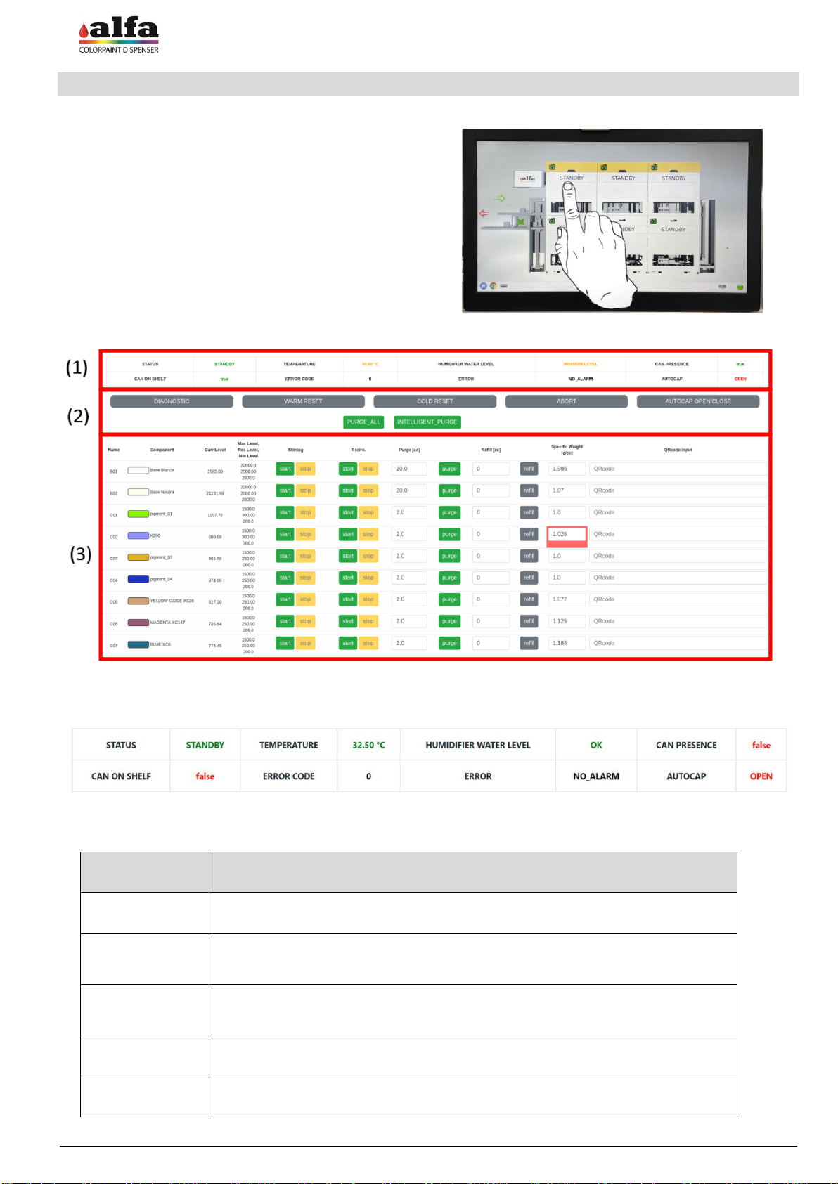
The bottom part (3) refers to the products circuits. Each line represents one circuit associated to a specific
product, while the columns contain parameters and controls of each circuit, as described in more details below.
Name
Description
NAME
The name of the circuit displayed as "CX" where X is a number from 01 to 16.
COMPONENT
The name of the product contained in the circuit and its RGB.
CURR LEVEL
The current level of the product contained in the circuit (expressed in cc).
MAX LEVEL
RES LEVEL
MIN LEVEL
The maximum level of product that can be contained in each circuit.
The product warning level (the circuit will continue to dispense).
The product minimum level (the circuit will stop to dispense.
STIRRING
Manual START and STOP stirring commands. When the stirring command is
given for a circuit, all the circuits of the same dispensing head are stirred because
the function is associated with the rotation of the turning table.
RECIRC
Manual START and STOP recirculation commands
PURGE (cc)
Purge a single circuit with the amout set by default. The value can be manually
increased or decreased by modifying the value displayed in the box.
REFILL (cc)
Refill a single circuit by the quanity expressed in cc. The command to rotate the
table will be executed to set ithe circuit to the refill position.
SPECIFIC
WEIGHT(g/cc)
At each refill the operator can manually modify the specific weight of the product
and the circuit will dispense accordingly.
QRcode INPUT
Scan the QRcode on the product’s package to complete all refill information
automatically (refill amount and specific weight).
Operator Manual –CR6
EN
ORDINARY MAINTENANCE AND CLEANING
9
MANUAL CONTROL PAGE
By clicking on the tools symbols you can access the manual
control page of each part of the machine.
Each manual control page consists of 3 main sections as
the image below:
•Commands (1): list of manual commands;
•Photocells (2): photocells status;
•Dispensing heads (3): dispensing heads status.
Operator Manual –CR6
10
ORDINARY MAINTENANCE AND CLEANING
EN
HOW TO PRODUCE A COLOR
1. Open the previously installed and configured File Watchdog application.
2. Open the Coins software and select the formula. Once you have chosen the formula and the amount,
the formula will be saved in the selected folder and Watchdog File will send it to the machine.
3. The color formula will appear on the right column in the order page. The page must be refreshed in
order to see the new orders.
4. Click the CREATE ORDER button, select the number of cans to be produced and click OK.
5. The new order will appear on the central column in the order page.
Operator Manual –CR6
EN
ORDINARY MAINTENANCE AND CLEANING
11
6. An order can be edited by clicking on the gear symbol. A pop up will show the color formula. Each line represents
a product that will be dispensed to reproduce the color formula. The color formula can be edited by modifying
the amount of each product to be dispensed, by adding a new product or by deleting one. The operator can then
select the number of cans to produce and print the required barcodes.
7. When an order is saved each can to be produce will appear on the left column in the order page. Here the
operator can click on each barcode symbol to print again each barcode.
8. Apply the barcode label on the can and position it on a shuttle with a greater or equal capacity of the requested
can.
Operator Manual –CR6
12
ORDINARY MAINTENANCE AND CLEANING
EN
9. Pay attention to position the barcode so that it can be fully read in the shuttle window (1) and position the shuttle
on the loading roller conveyor (2).
10. To start the production process, press the “green arrow” button (1). The software will carry out a consistency
check between the volume expected from the order (barcode reading) and the volume of the can (shuttle code
reading).
11. Wait for process completion, then remove the shuttle from the output roller conveyor by pressing the red arrow.
Operator Manual –CR6
EN
ORDINARY MAINTENANCE AND CLEANING
13
HOW TO REFILL A CANISTER
1. Each circuit can be set with a different reserve and minimum level when setting the machine. When a product
reaches the reserve level, an alarm will be shown.
ATTENTION! Every time an order is sent to be produced, the software calculates if the volume of each
product in the canisters is sufficient to complete the formula so that the residual volume is not lower
than the minimum level. In case one of the products is not sufficient, the system will not dispense the
formula.
2. To start the refill process please click on the automation button on the top of the Home Page to pause all
activities.
3. When the activities of all dispensing heads are paused, the refill tanks will become gree on all dispensing heads.
To proceed please click on the service button of the dispensing head where the canister to be refilled is
positioned.
Operator Manual –CR6
14
ORDINARY MAINTENANCE AND CLEANING
EN
4. Click on the REFILL button of the canister you need to top up. A pop up message will appear to confirm the
positioning of the canister in the front position of the dispensing head.
5. While the turning table is positioning the canister in the front position (if necessary), the status of the turning
table is ROTATING. When the positioning is completed the status becomes DIAGNOSTIC. Please wait the
DIAGNOSTIC status before opening the cover/extractable tray of the dispensing head.
6. WARNING! Do not force manually the turning table rotation. Use the software controls and wait that the machine
performs the necessary rotation.
Operator Manual –CR6
EN
ORDINARY MAINTENANCE AND CLEANING
15
7. When the status switches to DIAGNOSTIC, open the upper cover or the extractable tray. Remove the lid of the
canister in the front position. Fill the canister with the appropriate product without exceeding the maximum level
(MAX LEVEL).
8. After each top-up operation, you must record the quantity added in the circuit and it’s specific weight (if this was
different from the previous batch). These information are filled automatically when the operator scans the
QRcode present on the product’s package. In this case a pop up message will appear showing all information
recorded with the QRcode.
9. In alternative, the information can be filled manually by entering in the REFILL(cc) box the quantity of
product refilled and in the SPECIFIC WEIGHT (g/cc) box the new specific weight, then click the REFILL
button. A pop up box will appear to confim the amount refilled and the specific weight. If everything is
correct please press OK.
Operator Manual –CR6
16
ORDINARY MAINTENANCE AND CLEANING
EN
10. If another circuit in the same dispensing head must be topped up, please repeat the steps 3 to 8. When all
canisters are refilled, please close the top cover or the extractable tray and click the COLD RESET button.
11. A pop up message will inform you that the dispensing head is running the reset procedure. Please press OK.
Operator Manual –CR6
EN
ORDINARY MAINTENANCE AND CLEANING
17
HOW TO PURGE ONE CIRCUIT, MORE CIRCUITS OR ALL CIRCUITS
The purge function consists in dispensing a small quantity of product from one or several circuits, so as to ensure proper
cleaning of the dispensing circuits and prevent settling or drying out issues that could compromise machine operation.
To purge all circuits of all dispensing heads, please click on the button as shown in the image below. This will create a
new order called PURGE ALL and the related barcode. The order contains all products and its automatically created
with the defined purge quantity for each circuit.
On the other hand, the operator can decide to purge only one or more circuits. To do so, the shuttle must be moved
under each dispensing head using the manual commands, as described below.
1. Place a can in a shuttle and place it on the roller conveyor. Then click the “green arrow” (1) to move the shuttle
in front of the barcode reader.
2. When the shuttle is in fron of the barcode reader, press the TOOLS button to access the manual control page.
Operator Manual –CR6
18
ORDINARY MAINTENANCE AND CLEANING
EN
3. Move the shuttle under the first dispensing head by clicking the button below.
4. The software does not recognize this shuttle as part of an order, therefore the following pop up will appear.
Please click OK.
5. You can execute the command to purge a single circuit, as well as an automatic purging operation, which
dispenses a small amount of product from all the circuits present on the turning table (“PURGE ALL”).
6. During the purge cycle the status will change into DISPENSING. Wait for the machine to complete the purge
before sending new commands.
7. Repeat the same steps 2 to 6 to purge more circuits in other turning tables.
Operator Manual –CR6
EN
ORDINARY MAINTENANCE AND CLEANING
19
HOW TO MOVE THE SHUTTLE WITH MANUAL COMMANDS
By pressing the TOOLS button, the operator can access the manual control page, where all manual commands
buttons are located. Belo the example of how to move the shuttle from dispensing head 5 to 6 using the lifter.
1. Make sure tha shuttle is located under dispensing head 5.
2. Press the TOOL button on lifter to access its manual command page.
3. By clicking on “move 04 05 (‘C-> UP’)” the machine will automatically position the lifter up and load the
shuttle.
Operator Manual –CR6
20
ORDINARY MAINTENANCE AND CLEANING
EN
4. The status of the dispensing head 5 will become JAR_POSITIONING. Please wait until the status go back
to STANDBY.
5. Now click on “move 05 06 (‘UP-> DOWN’)” the machine will automatically move the lift with the shuttle
down.
6. The status of the dispensing head 6 will become JAR_POSITIONING. Please wait until the status go back
to STANDBY.

Other manuals for CR6

2

This manual suits for next models

1

Other Alfa Network Industrial Equipment manuals

Alfa Network CR6 User manual

Alfa Network

Alfa Network CR6 User manual

Alfa Network Alfa-V VDD User manual

Alfa Network

Alfa Network Alfa-V VDD User manual

Alfa Network LU-VE Optigo FMS25 User manual

Alfa Network

Alfa Network LU-VE Optigo FMS25 User manual

Alfa Network LU-VE Arctigo ISD User manual

Alfa Network

Alfa Network LU-VE Arctigo ISD User manual

Alfa Network KW User manual

Alfa Network

Alfa Network KW User manual

Alfa Network CR6 User manual

Alfa Network

Alfa Network CR6 User manual

Popular Industrial Equipment manuals by other brands

Alfalaval ALS Series instruction manual

Alfalaval

Alfalaval ALS Series instruction manual

BilJax Pro-Jax Utility Scaffold Assembly instructions

BilJax

BilJax Pro-Jax Utility Scaffold Assembly instructions

KEBCO COMBICOM instruction manual

KEBCO

KEBCO COMBICOM instruction manual

BilJax ST8100 Assembly instructions

BilJax

BilJax ST8100 Assembly instructions

SAM CARBIS SOLUTIONS GROUP, LLC TCG-1000 instruction manual

SAM CARBIS SOLUTIONS GROUP, LLC

SAM CARBIS SOLUTIONS GROUP, LLC TCG-1000 instruction manual

woodmizer SLPCTD3.6 Safety, operation and maintenance manual

woodmizer

woodmizer SLPCTD3.6 Safety, operation and maintenance manual

Oriental motor EZ limo EZS II Series quick start guide

Oriental motor

Oriental motor EZ limo EZS II Series quick start guide

EL-CELL ECC-Opto-Std user manual

EL-CELL

EL-CELL ECC-Opto-Std user manual

Lake Shore CRX-EM-HF instructions

Lake Shore

Lake Shore CRX-EM-HF instructions

Roadready IntelliStage IS8RC manual

Roadready

Roadready IntelliStage IS8RC manual

ABB HT563033 Operation manual

ABB

ABB HT563033 Operation manual

Jäger Z62-M450.01 S21 manual

Jäger

Jäger Z62-M450.01 S21 manual

Eaton iCube user manual

Eaton

Eaton iCube user manual

Jäger S62-M280.07 S5 manual

Jäger

Jäger S62-M280.07 S5 manual

Hengesbach LEVELTEC S Series operating instructions

Hengesbach

Hengesbach LEVELTEC S Series operating instructions

Humboldt HM-5035.3F product manual

Humboldt

Humboldt HM-5035.3F product manual

GAGEMAKER MIC TRAC MT-4000 Operation manual

GAGEMAKER

GAGEMAKER MIC TRAC MT-4000 Operation manual

Siemens SIMATIC NET S7-CPs Configuring and Installing

Siemens

Siemens SIMATIC NET S7-CPs Configuring and Installing

manuals.online logo
manuals.online logoBrands
  • About & Mission
  • Contact us
  • Privacy Policy
  • Terms and Conditions

Copyright 2025 Manuals.Online. All Rights Reserved.